window VOLVO XC60 2009 Owner´s Manual
[x] Cancel search | Manufacturer: VOLVO, Model Year: 2009, Model line: XC60, Model: VOLVO XC60 2009Pages: 297, PDF Size: 21.16 MB
Page 5 of 297
Contents* Option/accessory, for more information, see Introduction. 3
03
03
Your driving environment
Instruments and controls ..........................72
Ignition modes .......................................... 79
Seats......................................................... 81
Steering wheel .......................................... 86
Lighting ..................................................... 87
Wipers and washers................................. 93
Power windows......................................... 96
Mirrors....................................................... 98
Power panorama moonroof*................... 100
HomeLink® Wireless Control System* ...102
Starting the engine .................................. 105
Transmission ........................................... 109
Brakes..................................................... 112
Hill Descent Control (HDC) .....................114
Parking brake .......................................... 116
04
04Comfort and driving pleasure
Menus and messages .............................122
Climate system ....................................... 126
Audio system.......................................... 133
Bluetooth ® hands-free connection......... 147
Trip computer......................................... 153
Compass................................................. 154
Stability system....................................... 155
Active chassis system–Four C ................157
Cruise control.......................................... 158
Collision warning with Auto-brake*......... 160
City Safety™ .......................................... 166
Adaptive Cruise Control (ACC)* ..............172
Distance alert ......................................... 179
Driver Alert System*................................ 182
Park assist*............................................. 187
Park Assist Camera (PAC)* .................... 190
Blind Spot Information System*.............. 193
Passenger compartment convenience ...197
05
05 During your trip
Driving recommendations .......................202
Refueling ................................................. 206
Loading ................................................... 210
Cargo area .............................................. 213
Towing a trailer ....................................... 217
Emergency towing .................................. 220
Page 23 of 297
01 Safety
Supplemental Restraint System (SRS)01
21
WARNING\b
Children must never be allowed in the
front passenger\fs seat. Volvo recom-
mends that ALL occupants (adults and
children) shorter than 4 feet 7 inches
(140 cm) be seated in the back seat of
any vehicle with a passenger-side front
airbag.
\b Occupants in the front passenger\fs seat
must never sit on the edge of the seat,
sit leaning toward the instrument panel
or otherwise sit out of position.
\b The occupant\fs back must be as upright
as comfort allows and be against the
seat back with the seat belt properly
fastened.
\b Feet must be on the floor, e.g., not on
the dash, seat or out of the window.WARNING \b
No objects or accessory equipment,
e.g. dashboard covers, may be placed
on, attached to, or installed near the air
bag hatch (the area above the glove
compartment) or the area affected by
airbag deployment (see the illustration
on page 18).
\b There should be no loose articles, such
as coffee cups on the floor, seat, or
dashboard area.
\b Never try to open the airbag cover on
the steering wheel or the passenger\fs
side dashboard. This should only be
done by a trained and qualified Volvo
service technician.
\b Failure to follow these instructions can
result in injury to the vehicle occupants.
Page 30 of 297
01 SafetyVolvo Inflatable Curtain (VIC) 01
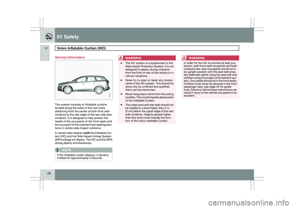
28 General information
This system consists of inflatable curtains
located along the sides of the roof liners,
stretching from the center of both front side
windows to the rear edge of the rear side door
windows. It is designed to help protect the
heads of the occupants of the front seats and
the occupant of the outboard rear seating posi-
tions in certain side impact collisions.
In certain side impacts, both the Inflatable Cur-
tain (VIC) and the Side Impact Airbag System
(SIPS airbag) will deploy. The VIC and the SIPS
airbag deploy simultaneously.
NOTE
If the inflatable curtain deploys, it remains
inflated for approximately 3 seconds.
WARNING \b
The VIC system is a supplement to the
Side Impact Protection System. It is not
designed to deploy during collisions
from the front or rear of the vehicle or in
rollover situations.
\b Never try to open or repair any compo-
nents of the VIC system. This should be
done only by a trained and qualified
Volvo service technician.
\b Never hang heavy items from the ceiling
handles. This could impede deployment
of the Inflatable Curtain.
\b The cargo area and rear seat should not
be loaded to a level higher than 2 in.
(5 cm) below the upper edge of the rear
side windows. Objects placed higher
than this level could impede the func-
tion of the Volvo Inflatable Curtain.WARNING In order for the VIC to provide its best pro-
tection, both front seat occupants and both
outboard rear seat occupants should sit in
an upright position with the seat belt prop-
erly fastened; adults using the seat belt and
children using the proper child restraint sys-
tem. Only adults should sit in the front seats.
Children must never be allowed in the front
passenger seat, see page 34 for guide-
lines. Failure to follow these instructions can
result in injury to the vehicle occupants in an
accident. G032025
Page 67 of 297
02 Locks and alarm
Child safety locks02
* Option/accessory, for more information, see Introduction. 65
Child safety locks
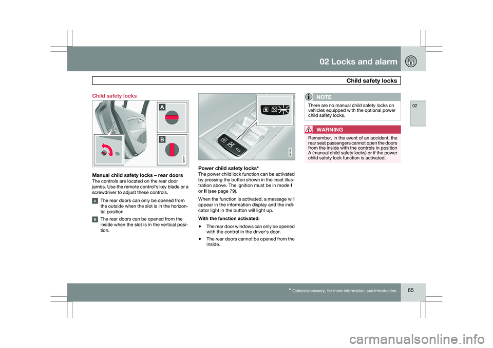
Manual child safety locks – rear doorsThe controls are located on the rear door
jambs. Use the remote control\fs key blade or a
screwdriver to adjust these controls.
The rear doors can only be opened from
the outside when the slot is in the horizon-
tal position.
The rear doors can be opened from the
inside when the slot is in the vertical posi-
tion.
Power child safety locks*The power child lock function can be activated
by pressing the button shown in the inset illus-
tration above. The ignition must be in mode
I
or II (see page 79).
When the function is activated, a message will
appear in the information display and the indi-
cator light in the button will light up.
With the function activated:
\b The rear door windows can only be opened
with the control in the driver\fs door.
\b The rear doors cannot be opened from the
inside.
NOTE There are no manual child safety locks on
vehicles equipped with the optional power
child safety locks.
WARNING
Remember, in the event of an accident, the
rear seat passengers cannot open the doors
from the inside with the controls in position
A (manual child safety locks) or if the power
child safety lock function is activated. G02107
7 G019300
Page 72 of 297
70
* Option/accessory, for more information, see Introduction. Instruments and controls
........................................................................\
72
Ignition modes ........................................................................\
................ 79
Seats........................................................................\
............................... 81
Steering wheel ........................................................................\
................ 86
Lighting ........................................................................\
........................... 87
Wipers and washers......................................................\
..........................
93
Power windows........................................................................\
............... 96
Mirrors........................................................................\
............................. 98
Power panorama moonroof*................................................................. 100
HomeLink® Wireless Control System* .................................................102
Starting the engine ........................................................................\
........ 105
Transmission ........................................................................\
................. 109
Brakes........................................................................\
........................... 112
Hill Descent Control (HDC).................................................................... 114
Parking brake ........................................................................\
................ 116
G02091
2
Page 79 of 297
03 Your driving environment
Instruments and controls03
}}
77
Generator not charging
This symbol comes on during driving if a fault
has occurred in the electrical system. Contact
an authorized Volvo workshop.
Engine temperatureEngine overheating can result from low oil or
coolant levels, towing or hard driving at high
heat and altitude, or mechanical malfunction.
Engine overheating will be signaled with text
and a red warning triangle in the middle of the
instrument display. The exact text will depend
on the degree of overheating. It may range
from "HIGH ENGINE TEMP – SLOW
DOWN" to "
HIGH ENGINE TEMP – STOP
ENGINE." If appropriate, other messages,
such as "COOLANT LEVEL LOW" will also be
displayed. If your engine does overheat so that
you must stop the engine, always allow the
engine to cool before attempting to check oil
and coolant levels.
Fault in brake system
If this symbol lights, the brake fluid level may
be too low. Stop the vehicle in a safe place and
check the level in the brake fluid reservoir, see
page 112. If the level in the reservoir is below
MIN, the vehicle should be transported to an
authorized Volvo workshop to have the brake
system checked. Canadian models are equipped with this sym-
bol: If the and symbols come on
at the same time, there may be a fault in the
brake force distribution system.
1. Stop the vehicle in a safe place and turn off
the engine.
2. Restart the engine.
\b If both symbols extinguish, continue driv-
ing.
\b If the symbols remain on, check the level in
the brake fluid reservoir, see page 227. If
the brake fluid level is normal but the sym-
bols are still lit, the vehicle can be driven,
with great care, to an authorized Volvo
workshop to have the brake system
checked.
\b If the level in the reservoir is below
MIN, the
vehicle should be transported to an author-
ized Volvo workshop to have the brake
system checked.
WARNING \b
If the fluid level is below the MIN mark
in the reservoir or if a warning message
is displayed in the text window:
DO
NOT DRIVE. Have the vehicle towed to
a trained and qualified Volvo service
technician and have the brake system
inspected.
\b If the ABS and Brake system lights are
on at the same time, there is a risk of
reduced vehicle stability.
Warning symbol
The red warning symbol comes on when a fault
has been indicated which could affect the
safety and/or drivability of the vehicle. An
explanatory text is shown on the information
display at the same time. The symbol remains
visible until the fault has been rectified but the
text message can be cleared with the READ
button, see page 123. The warning symbol can
also come on in conjunction with other sym-
bols.
Action:
1.
Stop in a safe place. Do not drive the vehi-
cle further.
2. Read the information on the information display. Implement the action in accord-
Page 81 of 297
03 Your driving environment
Ignition modes03
}}
79
Functions
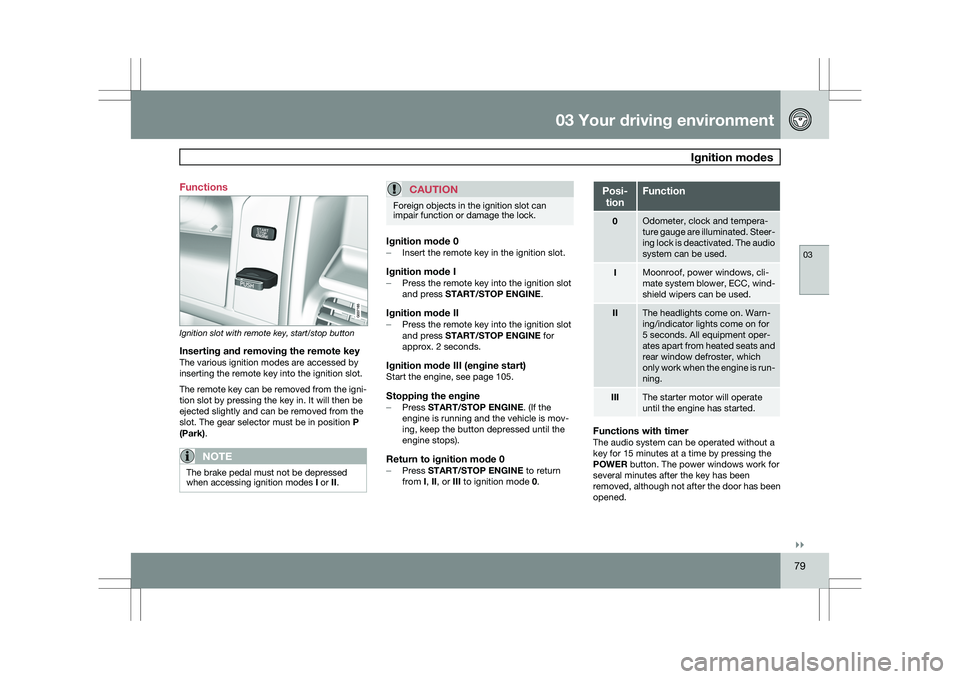
Ignition slot with remote key, start/stop button
Inserting and removing the remote keyThe various ignition modes are accessed by
inserting the remote key into the ignition slot.
The remote key can be removed from the igni-
tion slot by pressing the key in. It will then be
ejected slightly and can be removed from the
slot. The gear selector must be in position
P
(Park).
NOTE The brake pedal must not be depressed
when accessing ignition modes
I or II.
CAUTION Foreign objects in the ignition slot can
impair function or damage the lock.
Ignition mode 0–
Insert the remote key in the ignition slot.
Ignition mode I–Press the remote key into the ignition slot
and press START/STOP ENGINE.
Ignition mode II–Press the remote key into the ignition slot
and press START/STOP ENGINE for
approx. 2 seconds.
Ignition mode III (engine start)Start the engine, see page 105.
Stopping the engine–
Press START/STOP ENGINE. (If the
engine is running and the vehicle is mov-
ing, keep the button depressed until the
engine stops).
Return to ignition mode 0–Press START/STOP ENGINE to return
from I, II, or III to ignition mode 0. Posi-
tion Function
0 Odometer, clock and tempera-
ture gauge are illuminated. Steer-
ing lock is deactivated. The audio
system can be used.
I Moonroof, power windows, cli-
mate system blower, ECC, wind-
shield wipers can be used.
II The headlights come on. Warn-
ing/indicator lights come on for
5 seconds. All equipment oper-
ates apart from heated seats and
rear window defroster, which
only work when the engine is run-
ning.
III The starter motor will operate
until the engine has started.
Functions with timerThe audio system can be operated without a
key for 15 minutes at a time by pressing the
POWER button. The power windows work for
several minutes after the key has been
removed, although not after the door has been
opened.
Page 95 of 297
03 Your driving environment
Wipers and washers03
}}
* Option/accessory, for more information, see Introduction. 93
Windshield wipers/washers
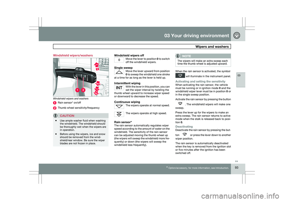
Windshield wipers and washers
Rain sensor* on/off
Thumb wheel sensitivity/frequency
CAUTION
\b
Use ample washer fluid when washing
the windshield. The windshield should
be thoroughly wet when the wipers are
in operation.
\b Before using the wipers, ice and snow
should be removed from the wind-
shield/rear window. Be sure the wiper
blades are not frozen in place.
Windshield wipers offMove the lever to position
0 to switch
off the windshield wipers.
Single sweepMove the lever upward from position
0 to sweep the windshield one stroke
at a time for as long as the lever is held up.
Intermittent wipingWith the lever in this position, you can
set the wiper interval by twisting the
thumb wheel upward to increase wiper speed
or downward to decrease the speed.
Continuous wipingThe wipers operate at normal speed. The wipers operate at high speed.
Rain sensor*The rain sensor automatically regulates wiper
speed according to the amount of water on the
windshield. The sensitivity of the rain sensor
can be adjusted moving the thumb wheel up
(the wipers will sweep the windshield more fre-
quently) or down (the wipers will sweep the
windshield less frequently).
NOTE The wipers will make an extra sweep each
time the thumb wheel is adjusted upward.
When the rain sensor is activated, the symbol
will illuminate in the instrument panel.
Activating and setting the sensitivityWhen activating the rain sensor, the vehicle
must be running or in ignition mode
II and the
windshield wiper lever must be in position 0 or
in the single sweep position.
Activate the rain sensor by pressing the button . The windshield wipers will make one
sweep.
Press the lever up for the wipers to make an
extra sweep. The rain sensor returns to active
mode when the stalk is released back to posi-
tion 0.
DeactivatingDeactivate the rain sensor by pressing the but-
ton or press the lever down to another
wiper position.
The rain sensor is automatically deactivated
when the key is removed from the ignition slot
or five minutes after the ignition has been
switched off. G031420
Page 98 of 297
03 Your driving environmentPower windows 03
96
* Option/accessory, for more information, see Introduction.
Power windows
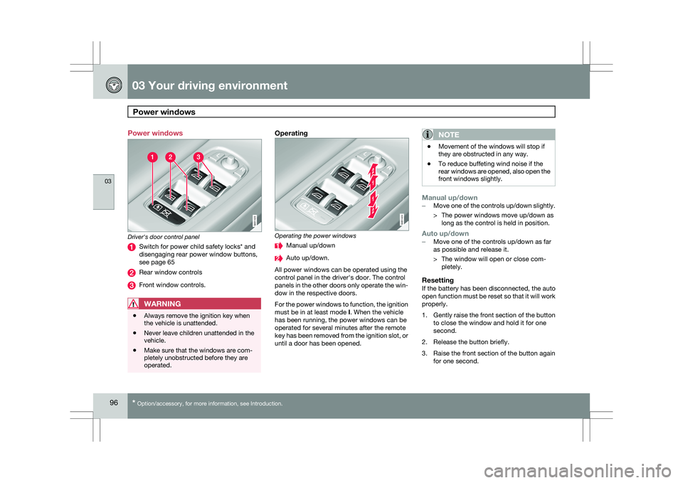
Driver's door control panel
Switch for power child safety locks* and
disengaging rear power window buttons,
see page 65
Rear window controls
Front window controls.
WARNING
\b
Always remove the ignition key when
the vehicle is unattended.
\b Never leave children unattended in the
vehicle.
\b Make sure that the windows are com-
pletely unobstructed before they are
operated.
Operating Operating the power windows
Manual up/down
Auto up/down.
All power windows can be operated using the
control panel in the driver\fs door. The control
panels in the other doors only operate the win-
dow in the respective doors.
For the power windows to function, the ignition
must be in at least mode I. When the vehicle
has been running, the power windows can be
operated for several minutes after the remote
key has been removed from the ignition slot, or
until a door has been opened.NOTE \b
Movement of the windows will stop if
they are obstructed in any way.
\b To reduce buffeting wind noise if the
rear windows are opened, also open the
front windows slightly.
Manual up/down–
Move one of the controls up/down slightly.
> The power windows move up/down as
long as the control is held in position.
Auto up/down– Move one of the controls up/down as far
as possible and release it.
> The window will open or close com-
pletely.
ResettingIf the battery has been disconnected, the auto
open function must be reset so that it will work
properly.
1. Gently raise the front section of the button
to close the window and hold it for one
second.
2. Release the button briefly.
3. Raise the front section of the button again for one second. G031423 G031424
Page 99 of 297
03 Your driving environment
Power windows03
* Option/accessory, for more information, see Introduction. 97
Laminated glass*This glass is reinforced to help pro-
vide protection against break-ins and
improved sound insulation in the
passenger compartment. The wind-
shield and other windows have laminated
glass.