dashboard VOLVO XC60 2016 Owner´s Manual
[x] Cancel search | Manufacturer: VOLVO, Model Year: 2016, Model line: XC60, Model: VOLVO XC60 2016Pages: 398, PDF Size: 9.98 MB
Page 37 of 398
02 Safety
02
35
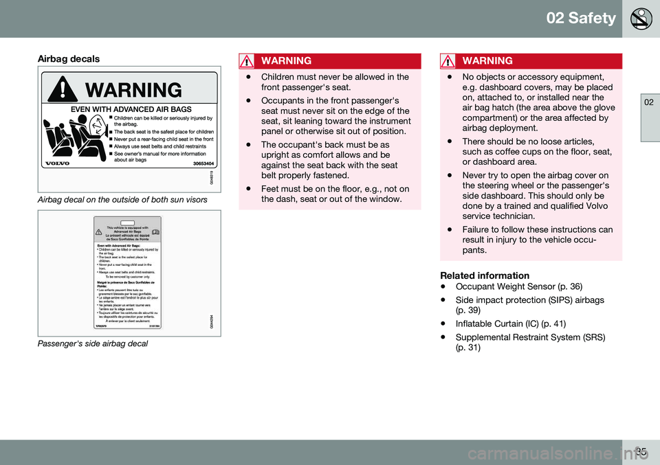
Airbag decals
Airbag decal on the outside of both sun visors
Passenger's side airbag decal
WARNING
•Children must never be allowed in the front passenger's seat.
• Occupants in the front passenger'sseat must never sit on the edge of theseat, sit leaning toward the instrumentpanel or otherwise sit out of position.
• The occupant's back must be asupright as comfort allows and beagainst the seat back with the seatbelt properly fastened.
• Feet must be on the floor, e.g., not onthe dash, seat or out of the window.
WARNING
•
No objects or accessory equipment, e.g. dashboard covers, may be placedon, attached to, or installed near theair bag hatch (the area above the glovecompartment) or the area affected byairbag deployment.
• There should be no loose articles,such as coffee cups on the floor, seat,or dashboard area.
• Never try to open the airbag cover onthe steering wheel or the passenger'sside dashboard. This should only bedone by a trained and qualified Volvoservice technician.
• Failure to follow these instructions canresult in injury to the vehicle occu-pants.
Related information
•
Occupant Weight Sensor (p. 36)
• Side impact protection (SIPS) airbags (p. 39)
• Inflatable Curtain (IC) (p. 41)
• Supplemental Restraint System (SRS)(p. 31)
Page 127 of 398
04 Climate
04
* Option/accessory, for more information, see Introduction.125
Climate – general information
The vehicle is equipped with Electronic Cli- mate Control (ECC) (p. 129) that cools, heatsor dehumidifies the air in the passenger com-partment.
Air conditioning
NOTE
• The air conditioning can be switched off, but to ensure the best possible cli-mate comfort in the passenger com-partment and to prevent the windowsfrom misting, it should always be on.
• In warm weather, a small amount ofwater may accumulate under the carwhen it has been parked. This water iscondensation from the A/C systemand is normal.
Side windows and laminated panoramic roof
To ensure that the air conditioning works optimally, the side windows, and the lamina-ted panoramic roof should be closed.
Fog on the inside of the windowsThe defroster function (p. 132) should beused to remove fog or mist from the inside ofthe windows. Keeping the windows cleanwith a commercially available window wash-ing spray will also help prevent fogging ormisting.
Temporary shut-off of the air conditioning
The air conditioning (p. 132) is momentarily disengaged during full acceleration or whendriving uphill with a trailer. This may result ina temporary increase in cabin temperature.
Ice and snowAlways keep the air intake grille at the base ofthe windshield free of snow.
Climate system maintenanceSpecial tools and equipment are required tomaintain and carry out repairs on the climatesystem. Work of this type should only bedone by a trained and qualified Volvo servicetechnician.
RefrigerantVolvo cares about the environment. The airconditioning system in your car contains aCFC-free refrigerant – R134a. This substancewill not deplete the ozone layer. The air con-ditioning system contains 1.76 lbs (800 g) ofR134a. The systems uses PAG oil.
Related information
•
Climate – sensors (p. 125)
• Climate – menu settings (p. 127)
Climate – sensors
The climate system utilizes a number of sen- sors to help regulate the temperature andhumidity level in the passenger compartment.
Sensor location
• The sunlight sensor is located on the top side of the dashboard.
NOTE
The sunlight sensor monitors which side of the car that is most exposed to sunlight.This can mean that the temperature maydiffer between the right and left-side airvents, even if the temperatures set for bothsides of the passenger compartment arethe same.
•The temperature sensor for the passen- ger compartment is located below the cli-mate control panel.
• The outside (ambient) temperature sensoris located on the door mirror.
• The humidity sensor* is located in theinterior rearview mirror.
NOTE
Do not cover or block the sensors with clothing or other objects.
Related information
•
Climate – general information (p. 125)
Page 130 of 398
||
04 Climate
04
128* Option/accessory, for more information, see Introduction.
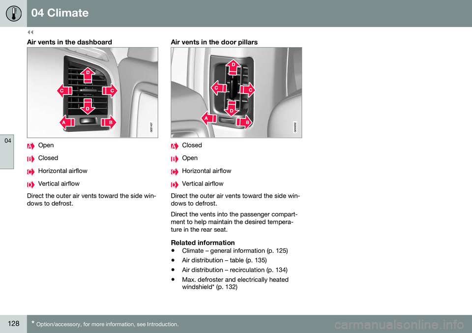
Air vents in the dashboard
Open
Closed
Horizontal airflow
Vertical airflow
Direct the outer air vents toward the side win- dows to defrost.
Air vents in the door pillars
Closed
Open
Horizontal airflow
Vertical airflow
Direct the outer air vents toward the side win- dows to defrost. Direct the vents into the passenger compart- ment to help maintain the desired tempera-ture in the rear seat.
Related information
• Climate – general information (p. 125)
• Air distribution – table (p. 135)
• Air distribution – recirculation (p. 134)
• Max. defroster and electrically heated windshield* (p. 132)
Page 131 of 398
04 Climate
04
* Option/accessory, for more information, see Introduction.129
Electronic climate control (ECC)
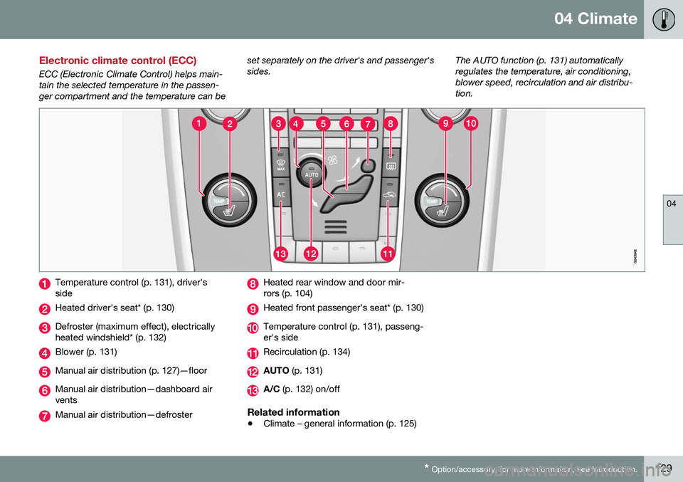
ECC (Electronic Climate Control) helps main- tain the selected temperature in the passen-ger compartment and the temperature can be set separately on the driver's and passenger'ssides.
The AUTO function (p. 131) automaticallyregulates the temperature, air conditioning,blower speed, recirculation and air distribu-tion.
Temperature control (p. 131), driver's side
Heated driver's seat* (p. 130)
Defroster (maximum effect), electrically heated windshield* (p. 132)
Blower (p. 131)
Manual air distribution (p. 127)—floor
Manual air distribution—dashboard air vents
Manual air distribution—defroster
Heated rear window and door mir- rors (p. 104)
Heated front passenger's seat* (p. 130)
Temperature control (p. 131), passeng- er's side
Recirculation (p. 134)
AUTO
(p. 131)
A/C (p. 132) on/off
Related information
•Climate – general information (p. 125)
Page 135 of 398
04 Climate
04
}}
* Option/accessory, for more information, see Introduction.133
NOTE
• Triangular areas at the far sides of the windshield are not heated electricallyand will take slightly longer todefrost/de-ice.
• The heated windshield may affect theperformance/range of e.g., transpond-ers used to automatically pay highwaytolls or other communication equip-ment.
The following occurs when the defroster/ windshield heating functions have been acti-vated: •
Blower speed increases automatically and the air conditioning (p. 132) willswitch on (if not already on and if the pas-senger compartment blower is not turnedoff) to dehumidify the air in the passengercompartment. Air conditioning can beswitched off by pressing the
AC button.
• Recirculation (p. 134) will not functionwhile defrost is engaged.
The climate system will return to its previous
settings when the defroster/windshield heat- ing function is switched off. See also Heated windshield*, rear window and door mirror defrosters (p. 104) for addi-tional information.
Related information
• Climate – general information (p. 125)
• Automatic climate control (p. 131)
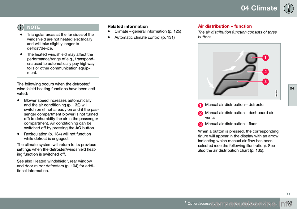
Air distribution – function
The air distribution function consists of three buttons.
Manual air distribution—defroster
Manual air distribution—dashboard air vents
Manual air distribution—floor
When a button is pressed, the corresponding figure will appear in the display with an arrowindicating which manual air flow has beenselected (see the following illustration). Seealso the air distribution chart (p. 135).
Page 137 of 398
04 Climate
04
}}
135
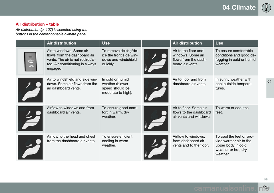
Air distribution – table
Air distribution (p. 127) is selected using the buttons in the center console climate panel.
Air distributionUseAir distributionUse
Air to windows. Some air flows from the dashboard airvents. The air is not recircula-ted. Air conditioning is alwaysengaged.To remove de-fog/de- ice the front side win-dows and windshieldquickly.Air to the floor and windows. Some airflows from the dash-board air vents.To ensure comfortable conditions and good de-fogging in cold or humidweather.
Air to windshield and side win- dows. Some air flows from theair dashboard vents.In cold or humid weather (blowerspeed should bemoderate to high).Air to floor and from dashboard air vents.In sunny weather with cool outside tempera-tures.
Airflow to windows and from dashboard air vents.To ensure good com- fort in warm, dryweather.Air to floor. Some air flows to the dashboardair vents and windows.To warm or cool the feet.
Airflow to the head and chest from the dashboard air vents.To ensure efficient cooling in warmweather.Airflow to windows, from dashboard airvents and to the floor.To cool the feet or pro- vide warmer air to theupper body in coldweather or hot, dryweather.
Page 168 of 398
06 Locks and alarm
06
166
Locking/unlocking – tailgate
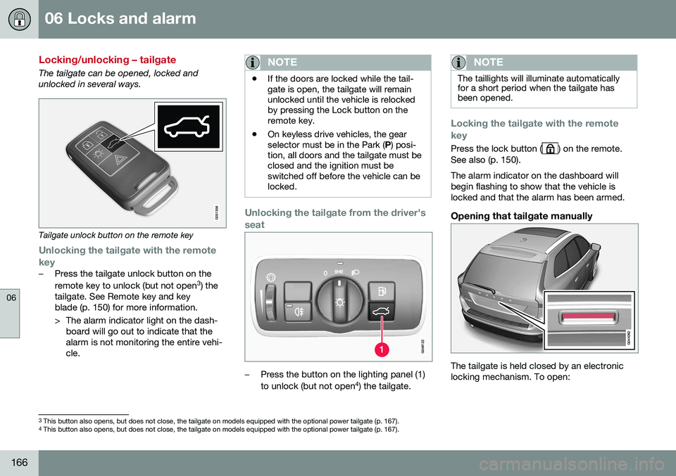
The tailgate can be opened, locked and unlocked in several ways.
Tailgate unlock button on the remote key
Unlocking the tailgate with the remote
key
–Press the tailgate unlock button on the remote key to unlock (but not open 3
) the
tailgate. See Remote key and key blade (p. 150) for more information.
> The alarm indicator light on the dash- board will go out to indicate that the alarm is not monitoring the entire vehi-cle.
NOTE
• If the doors are locked while the tail- gate is open, the tailgate will remainunlocked until the vehicle is relockedby pressing the Lock button on theremote key.
• On keyless drive vehicles, the gearselector must be in the Park (
P) posi-
tion, all doors and the tailgate must beclosed and the ignition must beswitched off before the vehicle can belocked.
Unlocking the tailgate from the driver's seat
–Press the button on the lighting panel (1) to unlock (but not open 4
) the tailgate.
NOTE
The taillights will illuminate automatically for a short period when the tailgate hasbeen opened.
Locking the tailgate with the remote key
Press the lock button () on the remote.
See also (p. 150). The alarm indicator on the dashboard will begin flashing to show that the vehicle islocked and that the alarm has been armed.
Opening that tailgate manually
The tailgate is held closed by an electronic locking mechanism. To open:
3 This button also opens, but does not close, the tailgate on models equipped with the optional power tailgate (p. 167).
4 This button also opens, but does not close, the tailgate on models equipped with the optional power tailgate (p. 167).
Page 172 of 398
06 Locks and alarm
06
170
Alarm indicator
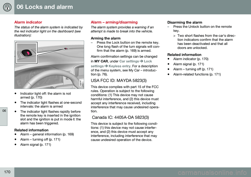
The status of the alarm system is indicated by the red indicator light on the dashboard (seeillustration):
•Indicator light off: the alarm is not armed (p. 170)
• The indicator light flashes at one-secondintervals: the alarm is armed
• The indicator light flashes rapidly beforethe remote key is inserted in the ignitionslot and the ignition is put in mode
I: the
alarm has been triggered.
Related information
• Alarm – general information (p. 169)
• Alarm – turning off (p. 171)
• Alarm signal (p. 171)
Alarm – arming/disarming
The alarm system provides a warning if an attempt is made to break into the vehicle.
Arming the alarm–Press the Lock button on the remote key. One long flash of the turn signals will con-firm that the alarm (p. 169) is armed.
Alarm confirmation settings can be changed in MY CAR , under
Car settingsLock
settings
Keyless entry. For a description
of the menu system, see My Car – introduc- tion (p. 76).
USA FCC ID: MAYDA 5823(3) This device complies with part 15 of the FCCrules. Operation is subject to the followingconditions: (1) This device may not causeharmful interference, and (2) this device mustaccept any interference received, includinginterference that may cause undesired opera-tion. Canada IC: 4405A-DA 5823(3) This device is subject to the following condi- tions: (1) this device may not cause interfer-ence, and (2) this device must accept anyinterference, including interference that maycause undesired operation of the device.
Disarming the alarm–Press the Unlock button on the remote key.
> Two short flashes from the car's direc- tion indicators confirm that the alarm has been deactivated and that alldoors are unlocked.
Related information
• Alarm indicator (p. 170)
• Alarm signal (p. 171)
• Alarm – turning off (p. 171)
• Alarm-related functions (p. 171)
Page 330 of 398
||
10 Maintenance and servicing
10
328
where any retailer can access or search for this information using your vehicle's VIN num-ber. This number can be found in your war-ranty booklet or on the dashboard at thelower left corner of the windshield.
–Select Maintenance & repairSend
vehicle data.
Booking information and vehicle dataWhen you opt to book service from your vehi- cle, booking information and vehicle data willbe transmitted. Vehicle data consists of anumber of parameters in the following areas:
• Service requirements
• Function status
• Fluid levels
• Odometer reading (mileage)
• Vehicle Identification Number (VIN)
• The vehicle's software version
Related information
•Volvo ID (p. 21)
Maintenance – opening/closing hood
The hood is opened by first releasing the lock from the passenger compartment and thenpressing the release control.
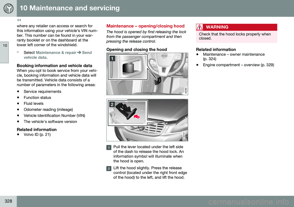
Opening and closing the hood
G031911
Pull the lever located under the left side of the dash to release the hood lock. Aninformation symbol will illuminate whenthe hood is open.
Lift the hood slightly. Press the release control (located under the right front edgeof the hood) to the left, and lift the hood.
WARNING
Check that the hood locks properly when closed.
Related information
•Maintenance – owner maintenance (p. 324)
• Engine compartment – overview (p. 329)
Page 372 of 398
||
11 Specifications
11
370
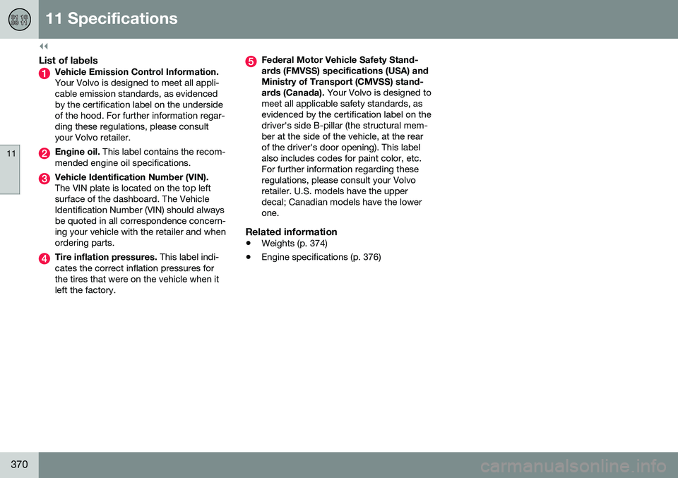
List of labelsVehicle Emission Control Information. Your Volvo is designed to meet all appli- cable emission standards, as evidencedby the certification label on the undersideof the hood. For further information regar-ding these regulations, please consultyour Volvo retailer.
Engine oil. This label contains the recom-
mended engine oil specifications.
Vehicle Identification Number (VIN). The VIN plate is located on the top left surface of the dashboard. The VehicleIdentification Number (VIN) should alwaysbe quoted in all correspondence concern-ing your vehicle with the retailer and whenordering parts.
Tire inflation pressures. This label indi-
cates the correct inflation pressures for the tires that were on the vehicle when itleft the factory.
Federal Motor Vehicle Safety Stand- ards (FMVSS) specifications (USA) andMinistry of Transport (CMVSS) stand- ards (Canada). Your Volvo is designed to
meet all applicable safety standards, as evidenced by the certification label on thedriver's side B-pillar (the structural mem-ber at the side of the vehicle, at the rearof the driver's door opening). This labelalso includes codes for paint color, etc.For further information regarding theseregulations, please consult your Volvoretailer. U.S. models have the upperdecal; Canadian models have the lowerone.
Related information
• Weights (p. 374)
• Engine specifications (p. 376)