ESP VOLVO XC60 2018 Owner´s Manual
[x] Cancel search | Manufacturer: VOLVO, Model Year: 2018, Model line: XC60, Model: VOLVO XC60 2018Pages: 660, PDF Size: 11.77 MB
Page 422 of 660
STARTING AND DRIVING
* Option/accessory.
420
ECO drive mode
The Eco drive mode optimizes the vehicle's driv- ing characteristics for more fuel-efficient andeco-friendly driving.
Use this mode to save fuel and promote eco- friendly driving. When ECO mode is activated, the following cha- racteristics are modified:
• The automatic transmission's shifting points.
• Engine control and accelerator pedalresponse.
• Eco Coast functionality is activated andengine braking is disabled when the acceler-ator pedal is released at speeds between65 and 140 km/h (40 and 87 mph).
• Some of the climate system settings will bereduced or switched off.
• The suspension's self-leveling function
* will
lower ground clearance to help reduce windresistance.
• Information will be shown in the ECO gaugein the instrument panel to help promotemore eco-friendly and economical driving.
Coast function Eco CoastEco Coast essentially deactivates engine braking,allowing the vehicle's kinetic energy to be usedto roll greater distances. When the driver releasesthe accelerator pedal, the transmission is auto-matically disengaged from the engine. Engine speed is reduced to idling speed to reduce fuelconsumption. This function is most effective in driving situa- tions where the vehicle can roll freely for a longdistance, e.g. on roads with slight downgrades orwhen a decrease in speed is anticipated, such aswhen approaching an area with a lower speedlimit.
Activating Eco Coast
The function is activated when the accelerator pedal is fully released and the following condi-tions are met:
• Eco drive mode is activated.
• The gear selector is in
D.
• The vehicle's speed is approximately65-140 km/h (40-87 mph).
• The gradient of the downgrade is less thanapproximately 6%.
COASTING will be displayed in the instrument
panel when Eco Coast is being used.
Limitations
Eco Coast is not available if:
• The engine and/or transmission are not at normal working temperatures.
• The gear selector is moved from
D to manual
shifting mode.
• The vehicle's speed is not within the65-140 km/h (40-87 mph) range. •
The gradient of the downgrade is more thanapproximately 6%.
• The steering wheel paddles
* are being used
for manual shifting.
Deactivating and turning off Eco Coast
In certain situations, it may be advisable to deac- tivate or turn off Eco Coast so that engine brak-ing can be used. These situations might includedriving down steep hills or before passinganother vehicle to help ensure this can be doneas safely as possible. Deactivate Eco Coast by:
• Pressing the accelerator or brake pedal.
• Moving the gear selector to manual mode.
• Using the steering wheel paddles
* to shift.
Turn off Eco Coast by:
• Switching drive mode
* or switching off drive
mode Eco in Function view.
It is possible to roll short distances even without Eco Coast in order to help conserve fuel. How-ever, for the best fuel economy, Eco Coast shouldbe activated and used to roll longer distances.
Cruise control Eco CruiseWhen cruise control is activated in the Eco drivemode, the vehicle's acceleration and decelerationwill be slower than in other drive modes to helpfurther conserve fuel. Because of this, the vehi-cle's actual speed may be slightly above or belowthe set speed.
Page 428 of 660
STARTING AND DRIVING
* Option/accessory.
426
Leveling control * and suspension
The vehicle's leveling control system adjusts the suspension and shock absorbers automaticallyto help provide good comfort and control whiledriving. Leveling can also be controlled manuallyto facilitate loading or getting in and out of thevehicle.
Pneumatic suspension and shock absorbers
The system is adapted to the selected drive mode and vehicle speed. The pneumatic suspen-sion reduces the vehicle's ground clearance athigher speeds to reduce air resistance andincrease stability. The shock absorbers are nor-mally set to provide the best possible comfort and are adjusted continuously according to theroad surface and the vehicle's acceleration, brak-ing and cornering.
The instrument panel indicateswhen the suspension level isbeing adjusted.The level cannot be adjusted when any of the side doors or the tailgate is open.
ParkingWhen parking, make sure that there is adequatespace above and below the vehicle since ground clearance may vary depending on e.g. ambienttemperature, how the vehicle is loaded, if loadingmode is used, which drive mode is selected afterthe engine is started, etc. The level may also be adjusted a period after the vehicle is parked. This is to compensate for anyheight changes that may occur due to tempera-ture changes in the air springs when the vehiclecools.
TransportingWhen transporting the vehicle on a ferry, train ortruck, only secure (lash) the vehicle around thetires, not using any other parts of the chassis.Changes in the pneumatic suspension may occurduring transport, which could adversely affect thelashing and result in damage.
Page 431 of 660
STARTING AND DRIVING
}}
* Option/accessory.429
Leveling control settings *
The vehicle can be lowered or raised to make it easier to load or for passengers to get in andout. Turn off leveling control before lifting the vehicle with a jack to help avoid problems with thepneumatic suspension.
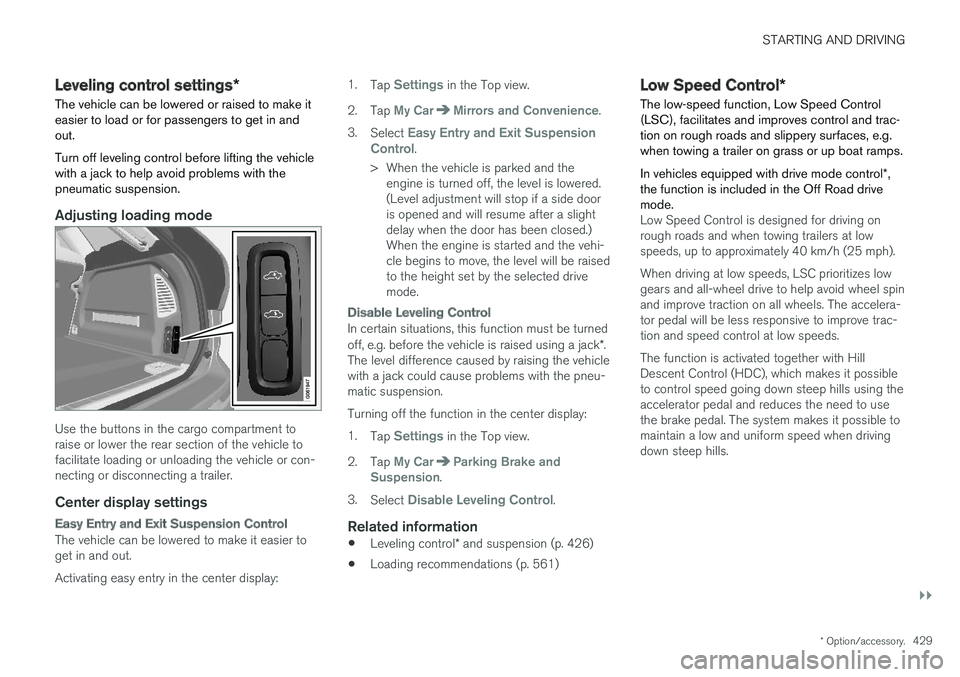
Adjusting loading mode
Use the buttons in the cargo compartment to raise or lower the rear section of the vehicle tofacilitate loading or unloading the vehicle or con-necting or disconnecting a trailer.
Center display settings
Easy Entry and Exit Suspension Control
The vehicle can be lowered to make it easier to get in and out. Activating easy entry in the center display: 1.
Tap
Settings in the Top view.
2. Tap
My CarMirrors and Convenience.
3. Select
Easy Entry and Exit Suspension
Control.
> When the vehicle is parked and the engine is turned off, the level is lowered. (Level adjustment will stop if a side dooris opened and will resume after a slightdelay when the door has been closed.)When the engine is started and the vehi-cle begins to move, the level will be raisedto the height set by the selected drivemode.
Disable Leveling Control
In certain situations, this function must be turned off, e.g. before the vehicle is raised using a jack *.
The level difference caused by raising the vehicle with a jack could cause problems with the pneu-matic suspension. Turning off the function in the center display:1. Tap
Settings in the Top view.
2. Tap
My CarParking Brake and
Suspension.
3. Select
Disable Leveling Control.
Related information
• Leveling control
* and suspension (p. 426)
• Loading recommendations (p. 561)
Low Speed Control
*
The low-speed function, Low Speed Control (LSC), facilitates and improves control and trac-tion on rough roads and slippery surfaces, e.g.when towing a trailer on grass or up boat ramps. In vehicles equipped with drive mode control *,
the function is included in the Off Road drive mode.
Low Speed Control is designed for driving on rough roads and when towing trailers at lowspeeds, up to approximately 40 km/h (25 mph). When driving at low speeds, LSC prioritizes low gears and all-wheel drive to help avoid wheel spinand improve traction on all wheels. The accelera-tor pedal will be less responsive to improve trac-tion and speed control at low speeds. The function is activated together with Hill Descent Control (HDC), which makes it possibleto control speed going down steep hills using theaccelerator pedal and reduces the need to usethe brake pedal. The system makes it possible tomaintain a low and uniform speed when drivingdown steep hills.
Page 432 of 660
||
STARTING AND DRIVING
* Option/accessory.
430
NOTE
When LSC with HDC is activated, the feel of the accelerator pedal and engine responsewill change.
NOTE
This drive mode is not designed to be used for normal street driving.
NOTE
The function is deactivated when driving at high speeds and must be reactivated at lowerspeeds if so desired.
Related information
• Activating and deactivating Low Speed Con- trol
* using the function button (p. 430)
• Changing drive mode
* (p. 419)
• Hill Descent Control
* (p. 431)
• All Wheel Drive (AWD)
* (p. 417)
Activating and deactivating Low
Speed Control
* using the functionbutton
Vehicles that are not equipped with drive mode controls in the tunnel console have a function button for Low Speed Control with
Hill Descent
Control in the center display's Function view.
Selecting Low Speed Control in the center display's Function view
–Tap the Hill Descent Control button to
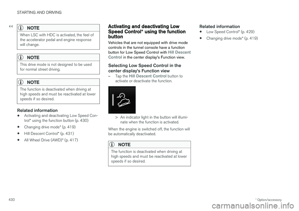
activate or deactivate the function.
> An indicator light in the button will illumi- nate when the function is activated.
When the engine is switched off, the function will be automatically deactivated.
NOTE
The function is deactivated when driving at high speeds and must be reactivated at lowerspeeds if so desired.
Related information
• Low Speed Control
* (p. 429)
• Changing drive mode
* (p. 419)
Page 433 of 660
STARTING AND DRIVING
* Option/accessory.431
Hill Descent Control *
The function for assisting when driving downhill, Hill Descent Control (HDC), is a low-speedfunction with increased engine braking. Thefunction makes it possible to increase ordecrease the vehicle's speed on steep downhillgradients by only using the accelerator pedal,without applying the brakes. In vehicles equipped with drive mode control *,
the function is included in the Off Road drive mode.
HDC is designed for driving on rough roads at low speeds and downhill gradients with slipperyor otherwise difficult road surfaces. The driverdoes not need to use the brake pedal but caninstead focus on steering.
WARNING
HDC is only intended to be a supplementary braking aid and it does not function in all sit-uations. The driver is always ultimately responsible for operating the vehicle in a safe manner.
FunctionHill Descent Control allows the vehicle to move forward or backward at very low speeds assistedby the brake system. The driver can increase thespeed by pressing the accelerator pedal. Whenthe accelerator pedal is released, the vehicle will return to very low speed regardless of how steepthe hill is and without the brakes needing to beapplied. The brake lights will illuminate when thefunction is activated. The driver can brake to stop or slow the vehicle at any time by depressing the brake pedal. HDC is activated along with Low Speed Control (LSC), which facilitates and improves traction andcontrol on rough and slippery surfaces. The sys-tem is intended to be used at low speeds, up toapproximately 40 km/h (25 mph).
To keep in mind when using HDC
•
If the function is switched off while driving ona steep downhill gradient, braking effect willbe gradually reduced.
• HDC can be used in gear positions
D and R,
and in manual gears 1 or 2.
• It is not possible to manually shift to thirdgear or higher when HDC is active.
NOTE
When LSC with HDC is activated, the feel of the accelerator pedal and engine responsewill change.
NOTE
This drive mode is not designed to be used for normal street driving.
NOTE
The function is deactivated when driving at high speeds and must be reactivated at lowerspeeds if so desired.
Related information
• Activating and deactivating Hill Descent Con- trol
* using the function button (p. 432)
• Changing drive mode
* (p. 419)
• Low Speed Control
* (p. 429)
• All Wheel Drive (AWD)
* (p. 417)
Page 442 of 660
STARTING AND DRIVING
* Option/accessory.
440
Overheating of engine andtransmission
In demanding driving conditions, such as driving in mountainous areas or hot weather, there is arisk of the engine or transmission overheating,especially when carrying heavy loads.
• Engine power may be temporarily limited.
• Remove any auxiliary lights mounted in front of the grille when driving in hot weather.
• If the temperature in the engine's coolingsystem becomes too high, a warning symbolwill appear in the instrument panel along with the message
Engine temperature High
temperature Stop safely. Pull over to a
safe location and let the engine idle for a few minutes to cool down.
• If the message
Engine temperature High
temperature Turn off engine or Engine
coolant Level low, turn off engine is dis-
played, stop the vehicle and turn off the engine.
• If the transmission begins to overheat, analternative gear shifting program will beselected. An integrated protective functionwill also be activated, the warning symbol will illuminate and the message
Transmission
warm Reduce speed to lower
temperature or Transmission hot Stop
safely, wait for cooling will be displayed in
the instrument panel. Follow the recommen- dations given by reducing speed or stopping the vehicle safely and letting the engine idle for a few minutes to let the transmissioncool.
• If the vehicle begins to overheat, the air con-ditioning may be temporarily switched off.
• After a prolonged period of driving indemanding conditions, do not turn off theengine immediately after stopping.
NOTE
It is normal for the engine's cooling fan to operate for a short time after the engine isswitched off.
Symbols in the instrument panel
SymbolMeaning
High engine temperature. Follow the recommendations provided.
Low coolant level. Follow the rec- ommendations provided.
Transmission hot/overheated/cool- ing. Follow the recommendationsprovided.
Related information
• Refilling coolant (p. 586)
• Driving with a trailer (p. 443)
• Preparing for a long trip (p. 433)
• Gear indicator
* (p. 416)
Page 443 of 660
STARTING AND DRIVING
}}
441
Battery drain The electrical functions in the vehicle drain the battery to varying degrees. Avoid using ignitionmode II when the engine is switched off. Use
ignition mode I instead, as this uses less electri-
cal current.
Note that certain accessories may also drain power from the electrical system. Do not usefunctions that use a lot of electrical current whenthe engine is turned off. Examples of such func-tions are:
• blower
• headlights
• windshield wipers
• audio system (especially at high volume).
If the starter battery voltage is low, a message isshown in the driver display. The vehicle's energy-saving function will then turn off or reduce certainfunctions, such as the blower and/or the audio system.
–Charge the battery by starting the engine and let it run for at least 15 minutes (drivingcharges the battery faster than letting theengine idle).
Related information
• Start battery (p. 592)
• Ignition modes (p. 401)
Jump starting using another battery
If the start battery is discharged, current from another battery can be used to start the vehicle.
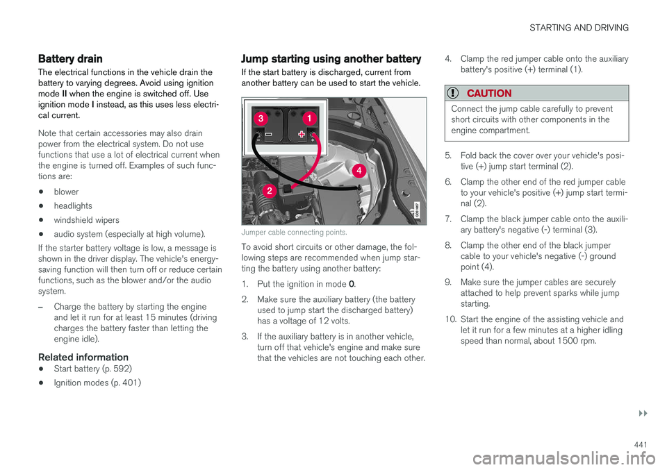
Jumper cable connecting points.
To avoid short circuits or other damage, the fol- lowing steps are recommended when jump star-ting the battery using another battery: 1. Put the ignition in mode 0.
2. Make sure the auxiliary battery (the battery used to jump start the discharged battery) has a voltage of 12 volts.
3. If the auxiliary battery is in another vehicle, turn off that vehicle's engine and make surethat the vehicles are not touching each other. 4. Clamp the red jumper cable onto the auxiliary
battery's positive (+) terminal (1).
CAUTION
Connect the jump cable carefully to prevent short circuits with other components in theengine compartment.
5. Fold back the cover over your vehicle's posi-tive (+) jump start terminal (2).
6. Clamp the other end of the red jumper cable to your vehicle's positive (+) jump start termi- nal (2).
7. Clamp the black jumper cable onto the auxili- ary battery's negative (-) terminal (3).
8. Clamp the other end of the black jumper cable to your vehicle's negative (-) groundpoint (4).
9. Make sure the jumper cables are securely attached to help prevent sparks while jumpstarting.
10. Start the engine of the assisting vehicle and let it run for a few minutes at a higher idlingspeed than normal, about 1500 rpm.
Page 445 of 660
STARTING AND DRIVING
}}
443
Installing the ball holder1. If necessary, remove the cotter pin from thelocking bolt and slide the locking bolt out of the towbar assembly.
2. Slide the ball holder into the towbar assem- bly.
3. Align the hole in the ball holder with the one in the towbar assembly.
4. Slide the locking bolt through the towbar assembly/ball holder.
5. Insert the cotter pin in the hole at the end of the locking bolt.
WARNING
• Be sure the towbar is securely locked in position before attaching anything to it.
• Always attach the trailer's safety wiresecurely to the towbar's safety wireattachment bracket.
Removing the ball holder1. Remove the cotter pin from the locking bolt
and slide the locking bolt out of the ballholder/towbar assembly.
2. Pull the ball holder out of the towbar assem- bly.
Stowing the ball holder
WARNING
When not in use, the detachable ball holder should always be properly stowed in the des-ignated location under the floor of the cargocompartment.
Related information
• Driving with a trailer (p. 443)
• Towing capacity and tongue weight (p. 636)
Driving with a trailer
There are a number of things to consider when towing a trailer, such as the towbar, the trailerand how the load is distributed in the trailer.
Load-carrying capacity is determined by the vehi- cle's curb weight. The total weight of all passen-gers and any installed accessories, e.g. towbar,reduces the vehicle's load-carrying capacity bythe corresponding amount. • Towbars used on the vehicle must be approved for the applicable use.
• Distribute the load on the trailer so that theweight on the towbar complies with thespecified maximum towball weight. Thetongue weight is calculated as part of thevehicle's payload.
• Increase the tire pressure to the recom-mended pressure for a full load.
• The engine is subjected to more load thanusual when towing a trailer.
• Towing a trailer affects the vehicle's han-dling, durability and driving economy.
• Do not drive with a heavy trailer when thevehicle is very new. Wait until the mileagehas reached at least 1000 km (620 miles).
• On long and steep downgrades, the vehicle'sbrakes are subjected to much more loadthan usual. When manually shifting, down-shift and adapt speed accordingly.
Page 453 of 660
STARTING AND DRIVING
}}
* Option/accessory.451
HomeLink
®
is delivered integrated in the rearview
mirror. The HomeLink ®
panel consists of three
programmable buttons and an indicator light in the mirror. For more information about HomeLink ®
, please
visit www.HomeLink.com, www.youtube.com/ HomeLinkGentex or call 1-800-355-3515. Save the original remote controls for future pro- gramming (e.g. for use in another vehicle). It isalso advisable to delete the button programmingif the vehicle is sold.
Related information
• Using HomeLink (p. 452)
• Programming HomeLink ®
* (p. 451)
• Type approval for HomeLink ®
* (p. 453)
Programming HomeLink®
*13
Follow these instructions to program HomeLink ®
, reset all programming, or program
individual buttons.
NOTE
In some vehicles, the ignition must be on or in the "accessory position" before HomeLink ®
can be programmed or used. It can be a good idea to put new batteries in the remote con- trol being replaced by HomeLink ®
for faster
programming and better radio signal trans-mission. The HomeLink ®
buttons should be
reset before programming.
WARNING
While HomeLink ®
is being programmed, the
garage door or gate being programmed may be activated. Make sure that no one is nearthe door or gate during programming. Whenprogramming a garage door opener, it isadvised to park outside of the garage. 1.
Point the remote control at the HomeLink ®
button to be programmed and hold it about 2-8 cm (1-3 inches) from the button. Do not obstruct the HomeLink ®
indicator light.
Note: Some remote controls are more effec-
tive at programming HomeLink ®
from a dis-
tance of about 15-20 cm (6-12 inches). Try moving the remote control closer or furtheraway if you are experiencing any difficultiesprogramming.
2. Press and hold both the remote control but- ton and the HomeLink ®
button to be pro-
grammed.
3. Do not release the buttons until the indicator light has stopped flashing slowly (about oncea second) and either flashes quickly (about10 times a second) or glows steadily. >Steady glow: Indication that program-
ming is complete. Press the programmed button twice to activate. Flashing quickly: The device being pro-
grammed with HomeLink ®
may have a
security function that requires an extra step. Try pressing the programmed buttontwice to see whether the programmingworks. Otherwise, continue with the fol-lowing steps.
12 HomeLink and the HomeLink house symbol are registered trademarks of Gentex Corporation.
13 Certain markets only.
Page 455 of 660
STARTING AND DRIVING
* Option/accessory.453
WARNING
•If you use HomeLink ®
to open a garage
door or gate, be sure no one is near the gate or door while it is in motion.
• Do not use HomeLink ®
with any garage
door opener that lacks safety stop andreverse features as required by US fed-eral safety standards (this includes anygarage door opener model manufacturedbefore April 1, 1982). A garage door thatcannot detect an object - signaling thedoor to stop and reverse - does not meetcurrent U.S. federal safety standards. Formore information, contact HomeLink at:www.homelink.com.
Related information
• HomeLink ®
* (p. 450)
• Programming HomeLink ®
* (p. 451)
• Type approval for HomeLink ®
* (p. 453)
Type approval for HomeLink®
*15
FCC (USA) and IC (Canada)This device complies with FCC rules part 15 and Industry Canada RSS-210. Operation is subjectto the following two conditions: (1) This devicemay not cause harmful interference, and (2) Thisdevice must accept any interference that may bereceived including interference that may causeundesired operation.
WARNING
The transmitter has been tested and complies with FCC and IC rules. Changes or modifica-tions not expressly approved by the partyresponsible for compliance could void the user's authority to operate the device. 16
Type approval for EUGentex Corporation hereby declares that HomeLink®
Model UAHL5 complies with the
Radio equipment directive 2014/53/EU. Wavelengths within which the radio equipment operates:
• 433.05MHz-434.79MHz <10mW E.R.P.
• 868.00MHz-868.60MHz <25mW E.R.P.
• 868.70MHz-868.20MHz <25mW E.R.P.
• 869.40MHz-869.65MHz <25mW E.R.P. •
869.70MHz-870.00MHz <25mW E.R.P.
Certificate holder address: Gentex Corporation,600 North Centennial Street, Zeeland MI 49464,USA For more information, see support.volvocars.com.
Related information
• HomeLink ®
* (p. 450)
15
Certain markets only.
16 The term "IC:" before the certification/registration number only signifies that Industry Canada technical specifications were met.