charger VOLVO XC60 2018 Owner´s Manual
[x] Cancel search | Manufacturer: VOLVO, Model Year: 2018, Model line: XC60, Model: VOLVO XC60 2018Pages: 660, PDF Size: 11.77 MB
Page 235 of 660
KEY, LOCKS AND ALARM
}}
* Option/accessory.233
InterferenceElectromagnetic fields or obstructing objects may interfere with the remote key's functions for key- less start and keyless locking and unlocking *.
NOTE
Avoid storing the remote control key near metal objects or electronic devices, e.g. cellphones, tablets, laptops or chargers – pref-erably no closer than 10-15 cm (4-6 in.).
If you experience interference, use the remote key's detachable blade to unlock the vehicle andplace the remote key in the backup key reader inthe tunnel console cup holder to disarm thealarm.
NOTE
When the remote control key is placed in the cup holder, make sure that no other vehiclekeys, metal objects or electronic devices (e.g.cell phones, tablets, laptops or chargers) arefound in the cup holder. Multiple vehicle keysclose to each other in the cup holder can dis-rupt their functionality.
Related information
• Locking and unlocking using the remote key (p. 233)
• Remote key range (p. 235) •
Replacing the remote key's battery (p. 236)
• Detachable key blade (p. 242)
• Red Key - restricted remote key
* (p. 240)
• Electronic immobilizer (p. 244)
Locking and unlocking using theremote key
All doors, tailgate and fuel filler door can be locked and unlocked simultaneously using thebuttons on the remote key.
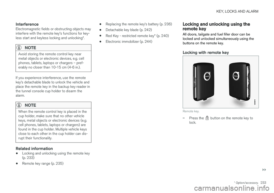
Locking with remote key
Remote key.
–Press the button on the remote key to
lock.
Page 401 of 660
STARTING AND DRIVING
}}
399
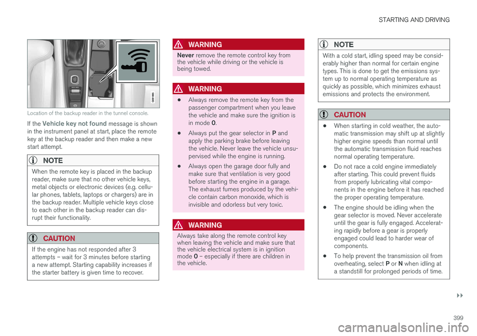
Location of the backup reader in the tunnel console.
If the Vehicle key not found message is shown
in the instrument panel at start, place the remote key at the backup reader and then make a newstart attempt.
NOTE
When the remote key is placed in the backup reader, make sure that no other vehicle keys,metal objects or electronic devices (e.g. cellu-lar phones, tablets, laptops or chargers) are inthe backup reader. Multiple vehicle keys closeto each other in the backup reader can dis-rupt their functionality.
CAUTION
If the engine has not responded after 3 attempts – wait for 3 minutes before startinga new attempt. Starting capability increases ifthe starter battery is given time to recover.
WARNING
Never remove the remote control key from
the vehicle while driving or the vehicle is being towed.
WARNING
• Always remove the remote key from the passenger compartment when you leavethe vehicle and make sure the ignition is in mode
0.
• Always put the gear selector in
P and
apply the parking brake before leaving the vehicle. Never leave the vehicle unsu-pervised while the engine is running.
• Always open the garage door fully andmake sure that ventilation is very goodbefore starting the engine in a garage.The exhaust fumes produced by the vehi-cle contain carbon monoxide, which isinvisible and odorless but very toxic.
WARNING
Always take along the remote control key when leaving the vehicle and make sure thatthe vehicle electrical system is in ignition mode
0 – especially if there are children in
the vehicle.
NOTE
With a cold start, idling speed may be consid- erably higher than normal for certain enginetypes. This is done to get the emissions sys-tem up to normal operating temperature asquickly as possible, which minimizes exhaustemissions and protects the environment.
CAUTION
• When starting in cold weather, the auto- matic transmission may shift up at slightlyhigher engine speeds than normal untilthe automatic transmission fluid reachesnormal operating temperature.
• Do not race a cold engine immediatelyafter starting. This could prevent fluidsfrom properly lubricating vital compo-nents in the engine before it has reachedthe proper operating temperature.
• The engine should be idling when thegear selector is moved. Never accelerateuntil the gear is fully engaged. Accelerat-ing rapidly before a gear is properlyengaged could lead to harder wear ofcomponents.
• To help prevent the transmission oil from overheating, select
P or N when idling at
a standstill for prolonged periods of time.
Page 437 of 660
STARTING AND DRIVING
* Option/accessory.435
Driving through standing water
Driving the vehicle through a deep pool of stand- ing water on a water-covered roadway is calledfording. This must be done with great caution.
The vehicle can be driven through water up to a depth of 40 cm (15.7 in) at no more than walkingspeed. Be particularly careful when drivingthrough flowing water. When driving through standing water, drive slowly and do not stop the vehicle. When you havepassed the water, press lightly on the brake pedaland check that the brakes are functioning prop-erly. Water, mud, slush, etc. can make the brakelinings slippery, resulting in delayed brakingeffect.
• If the vehicle is equipped with contacts for anelectric heater or trailer coupling, clean theseafter driving in water or mud.
• Do not allow the vehicle to stand in water upto the sills any longer than absolutely neces-sary. This could result in electrical malfunc-tions.
CAUTION
•Engine damage could occur if water enters the air cleaner.
• If water enters the transmission, the lubri-cating ability of the oils is reduced andthe service life of these systems is short-ened.
• Damage to any component, engine,transmission, turbocharger, differential orits internal components caused by flood-ing, vapor lock or insufficient oil is notcovered under warranty.
• If the engine stalls while the vehicle is inwater, do not attempt to restart it. Havethe vehicle towed out of the water to aworkshop. An authorized Volvo workshopis recommended. Risk of engine failure.
Related information
• Recovery (p. 450)
• Low Speed Control
* (p. 429)
Opening/closing the fuel filler door The vehicle must be unlocked before the fuel filler door can be opened 6
.
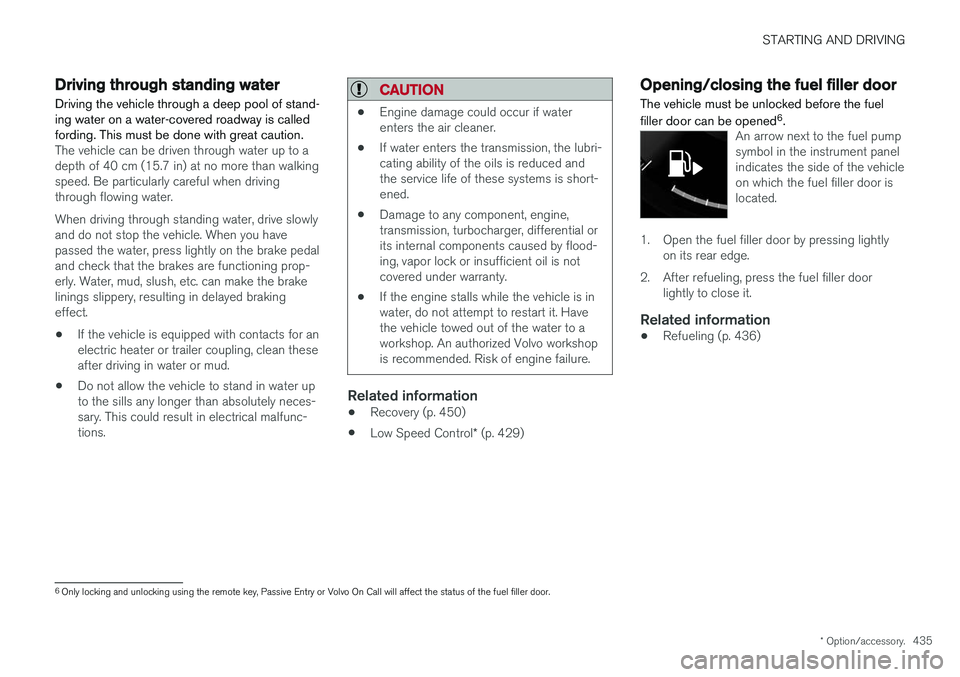
An arrow next to the fuel pump symbol in the instrument panelindicates the side of the vehicleon which the fuel filler door islocated.
1. Open the fuel filler door by pressing lightly
on its rear edge.
2. After refueling, press the fuel filler door lightly to close it.
Related information
• Refueling (p. 436)
6
Only locking and unlocking using the remote key, Passive Entry or Volvo On Call will affect the status of the fuel filler door.
Page 558 of 660
LOADING, STORAGE AND PASSENGER COMPARTMENT
* Option/accessory.
556
Electrical outlets
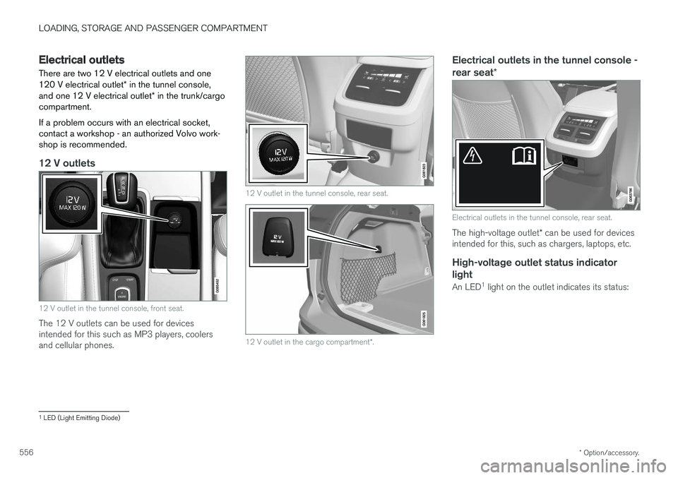
There are two 12 V electrical outlets and one 120 V electrical outlet * in the tunnel console,
and one 12 V electrical outlet * in the trunk/cargo
compartment. If a problem occurs with an electrical socket, contact a workshop - an authorized Volvo work-shop is recommended.
12 V outlets
12 V outlet in the tunnel console, front seat.
The 12 V outlets can be used for devices intended for this such as MP3 players, coolersand cellular phones.
12 V outlet in the tunnel console, rear seat.
12 V outlet in the cargo compartment *.
Electrical outlets in the tunnel console - rear seat *
Electrical outlets in the tunnel console, rear seat.
The high-voltage outlet * can be used for devices
intended for this, such as chargers, laptops, etc.
High-voltage outlet status indicator
light
An LED 1
light on the outlet indicates its status:
1 LED (Light Emitting Diode)
Page 560 of 660
LOADING, STORAGE AND PASSENGER COMPARTMENT
* Option/accessory.
558
Using the electrical outlets
The 12 V outlet can be used for devices intended for this such as MP3 players, coolersand cellular phones. The high-voltage outlet * can be used for devices
intended for this, such as chargers, laptops, etc.
The ignition must be in at least mode I for the
outlets to supply current. The outlets will then be active as long as there is sufficient charge in thestart battery. If the engine is turned off and the vehicle is locked, the outlets will be deactivated. If theengine is turned off and the vehicle remainsunlocked, the sockets will remain active for up to7 minutes.
NOTE
Bear in mind that using the electrical outlets when the engine is off could cause the starterbattery to have too low of a charge level,which could limit other functionality. Accessories connected to the electrical out- lets can be activated even when the vehicleelectrical system is off or if preconditioning isused. For this reason, disconnect plugs whenthey are not in use to prevent the starter bat-tery from becoming discharged.
WARNING
• Do not use accessories with large or heavy plugs – they could damage the out-let or come loose while you are driving.
• Do not use accessories that could causedisruptions to e.g. the vehicle's radioreceiver or electrical system.
• Position the accessory so that there is norisk of it injuring the driver or passengersin the event of heavy braking or a colli-sion.
• Pay attention to connected accessoriesas they can generate heat that could burnpassengers or the interior.
Using 12 V outlets1. Remove the stopper (tunnel console) or fold
down the cover (trunk/cargo compartment)over the socket and plug in the device.
2. Unplug the device and put the stopper back in (tunnel console) or fold up the cover(trunk/cargo compartment) when the socketis not in use or left unattended.
CAUTION
The maximum power is 120 W (10 A) per outlet.
Using high-voltage outletsThe ignition must be in at least mode I for outlets
to supply current. The outlets will then be active as long as there is sufficient charge in the startbattery. 1. Slide down the cover over the outlet and plug in the device. >
The LED 2
light on the outlet will indicate
its status.
2. The outlet is supplying electrical current when the light is glowing steadily green.
3. Disconnect the device by pulling out the plug (do not pull on the cord). Pull up the cover when the outlet is not in use or is left unattended.
CAUTION
The maximum power is 150 W.
WARNING
Do not attempt to alter or repair the high-volt- age outlet on your own. Volvo recommendscontacting an authorized Volvo workshop.
2LED (Light Emitting Diode)
Page 594 of 660
MAINTENANCE AND SERVICE
592
Start battery
The vehicle has a single-pole electrical system that uses the chassis and engine mount as con-ductors. The start battery is used to start the electrical system and power the starter motor and otherelectrical equipment in the vehicle. The start battery should only be replaced by a workshop 17
.
The vehicle has a voltage-regulated alternating current generator. The starter battery is a 12 V battery, designed for the carbon dioxide reducing functions Start/Stopand regenerative charging, and to support thefunctionality of the car's different systems. The service life and performance of the start bat- tery are affected by factors such as driving style,driving conditions, climate, battery discharges,number of starts, etc.
• Never disconnect the start battery while theengine is running.
• Make sure the cables to the start battery arecorrectly connected and the clamps aresecurely tightened.
WARNING
•Batteries generate hydrogen gas, which is flammable and explosive.
• Do not connect the jumper cable to anypart of the fuel system or to any movingparts. Avoid touching hot manifolds.
• Battery fluid contains sulfuric acid. Do notallow battery fluid to contact eyes, skin,fabrics or painted surfaces.
• If contact occurs, flush the affected areaimmediately with water. Obtain medicalhelp immediately if eyes are affected.
• Never expose the battery to open flameor electric spark. Do not smoke near thebattery. Failure to follow the instructionsfor jump starting can lead to injury.
Connection points
WARNING
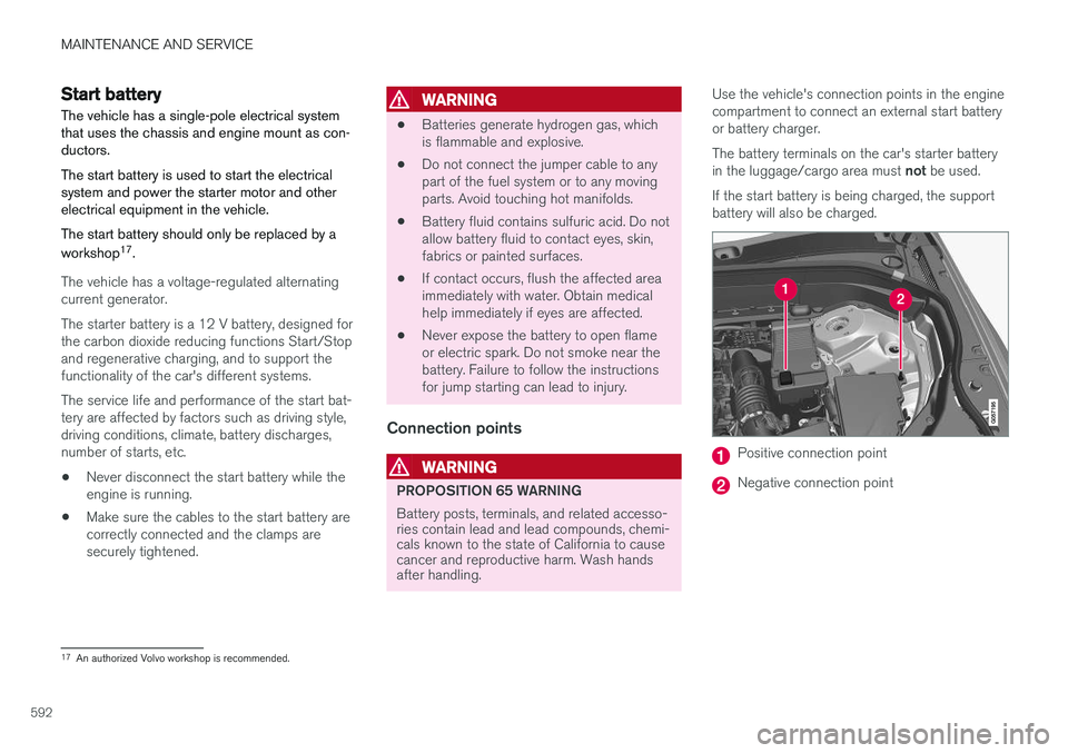
PROPOSITION 65 WARNING Battery posts, terminals, and related accesso- ries contain lead and lead compounds, chemi-cals known to the state of California to causecancer and reproductive harm. Wash handsafter handling. Use the vehicle's connection points in the engine compartment to connect an external start batteryor battery charger. The battery terminals on the car's starter battery in the luggage/cargo area must
not be used.
If the start battery is being charged, the support battery will also be charged.
Positive connection point
Negative connection point
17 An authorized Volvo workshop is recommended.
Page 595 of 660
MAINTENANCE AND SERVICE
}}
593
CAUTION
Only a modern battery charger with controlled charge voltage should be used to charge thestarter battery and support battery. The rapidcharging function should not be used as thiscould damage the battery.
CAUTION
Failure to observe the following could cause the infotainment energy save mode to tempo-rarily stop working and/or a message in thedriver's display regarding the state of chargeof the starter battery may be temporarilyincorrect after an external starter battery orbattery charger has been connected:
• The negative battery terminal of the vehi- cle's starter battery must
never be used
to connect an external starter battery orbattery charger – only the vehicle's neg-
ative charging point should be used as
a grounding point.
NOTE
If the starter battery becomes discharged too many times, it will shorten its service life. The service life of the starter battery is affec- ted by several factors, such as driving condi-tions and climate. The starting capacity of thebattery reduces gradually over time. The bat-tery must therefore be recharged if the vehi-cle is not used or a long period of time or if itis only driven short distances. Severe cold fur-ther limits the starting capacity. To keep the starter battery in a good condi- tion, the vehicle should be driven at least15 minutes per week or the battery should beconnected to a battery charger with automatictrickle charging. A starter battery that is always kept fully charged has the maximum service life.
Location
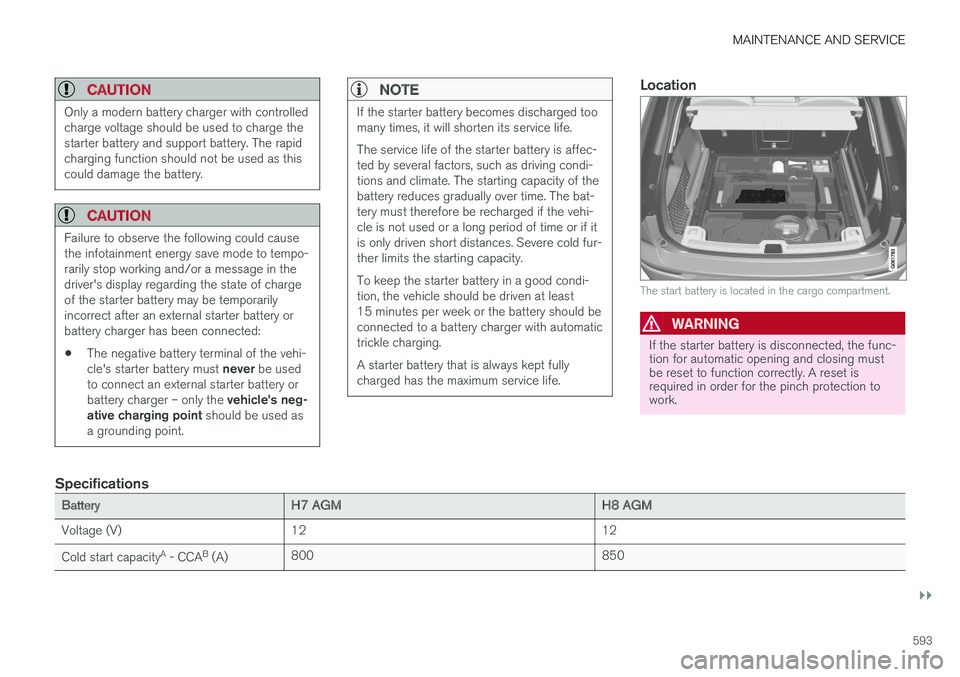
The start battery is located in the cargo compartment.
WARNING
If the starter battery is disconnected, the func- tion for automatic opening and closing mustbe reset to function correctly. A reset isrequired in order for the pinch protection towork.
Specifications
BatteryH7 AGMH8 AGM
Voltage (V) 12 12
Cold start capacity A
- CCA B
(A) 800
850
Page 597 of 660
MAINTENANCE AND SERVICE
}}
595
Support battery In addition to the start battery, vehicles equipped with the Start/Stop function also have a supportbattery.
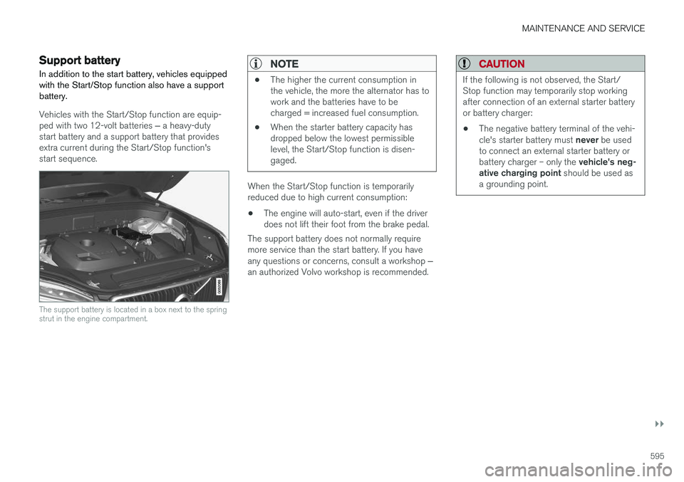
Vehicles with the Start/Stop function are equip- ped with two 12-volt batteries ‒ a heavy-duty
start battery and a support battery that provides extra current during the Start/Stop function'sstart sequence.
The support battery is located in a box next to the spring strut in the engine compartment.
NOTE
• The higher the current consumption in the vehicle, the more the alternator has towork and the batteries have to becharged = increased fuel consumption.
• When the starter battery capacity hasdropped below the lowest permissiblelevel, the Start/Stop function is disen-gaged.
When the Start/Stop function is temporarily reduced due to high current consumption:
• The engine will auto-start, even if the driverdoes not lift their foot from the brake pedal.
The support battery does not normally requiremore service than the start battery. If you have any questions or concerns, consult a workshop ‒
an authorized Volvo workshop is recommended.
CAUTION
If the following is not observed, the Start/ Stop function may temporarily stop workingafter connection of an external starter batteryor battery charger: • The negative battery terminal of the vehi- cle's starter battery must
never be used
to connect an external starter battery orbattery charger – only the vehicle's neg-
ative charging point should be used as
a grounding point.
Page 598 of 660
||
MAINTENANCE AND SERVICE
596
NOTE
If the starter battery is discharged to the extent that the vehicle does not have normalelectrical functions and the engine must thenbe jump-started with an external battery or abattery charger, the Start/Stop function mayremain activated. If the Start/Stop functionshortly thereafter auto-stops the engine, thereis a huge risk that auto-start of the engine willfail due to insufficient battery capacity sincethe battery had not had time to recharge. If the vehicle has been jump-started or if there has not been enough time for the bat-tery to be charged with a battery charger, it isadvisable to temporarily deactivate theStart/Stop function until the battery has beenrecharged by the vehicle. At an ambient tem-perature of about +15°C (about 60°F), thebattery must be charged by the vehicle for atleast one hour. At lower ambient tempera-tures, the charging time can increase to3-4 hours. It is advisable to charge the batterywith an external battery charger.
Specifications
Voltage (V) 12 Cold start capacityA
-
CCA B
(A) 170
Dimensions, L×W×H150×90×130 mm
(5.9×3.5×5.1 inches)
Capacity (Ah) 10
A According to EN standard.
B Cold Cranking Amperes.
CAUTION
When replacing the starter battery or support battery, an AGM 19
battery must be installed.
Related information
• Start battery (p. 592)
• Start/Stop function (p. 422)
• Battery symbols (p. 596)
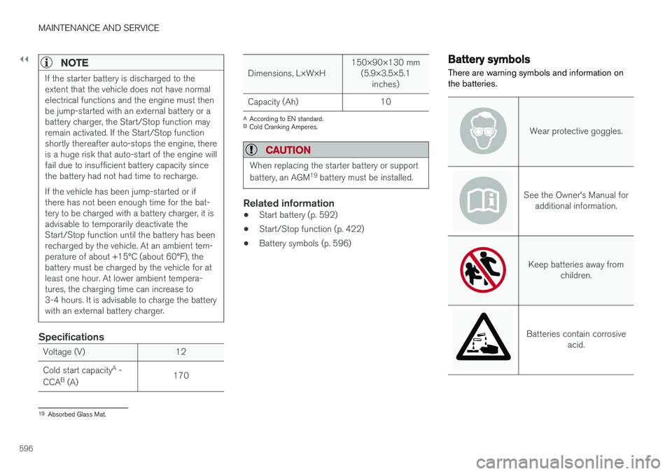
Battery symbols
There are warning symbols and information on the batteries.
Wear protective goggles.
See the Owner's Manual for additional information.
Keep batteries away from children.
Batteries contain corrosive acid.
19Absorbed Glass Mat.
Page 602 of 660
||
MAINTENANCE AND SERVICE
* Option/accessory.
600 Fuse pliers are provided on the inside of the fuse box cover to assist in removing and insertingfuses. There are also spaces for several extra fuses in the fusebox.
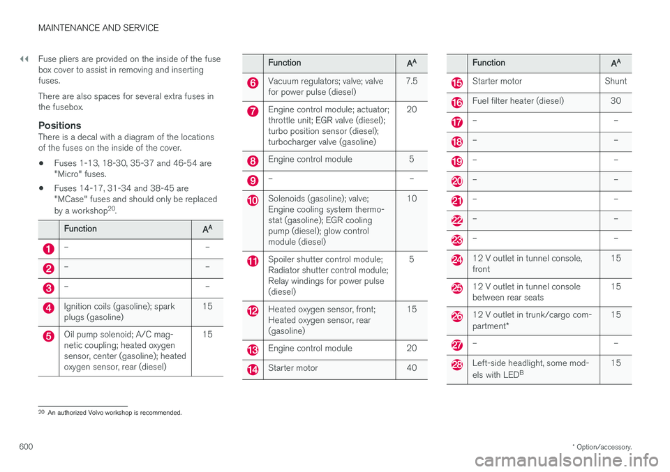
PositionsThere is a decal with a diagram of the locationsof the fuses on the inside of the cover.
• Fuses 1-13, 18-30, 35-37 and 46-54 are"Micro" fuses.
• Fuses 14-17, 31-34 and 38-45 are"MCase" fuses and should only be replaced by a workshop 20
.
FunctionAA
– –
– –
– –
Ignition coils (gasoline); spark plugs (gasoline) 15
Oil pump solenoid; A/C mag- netic coupling; heated oxygensensor, center (gasoline); heatedoxygen sensor, rear (diesel)15
FunctionAA
Vacuum regulators; valve; valve for power pulse (diesel)
7.5
Engine control module; actuator; throttle unit; EGR valve (diesel);turbo position sensor (diesel);turbocharger valve (gasoline) 20
Engine control module 5
– –
Solenoids (gasoline); valve; Engine cooling system thermo-stat (gasoline); EGR coolingpump (diesel); glow controlmodule (diesel)10
Spoiler shutter control module; Radiator shutter control module;Relay windings for power pulse(diesel)
5
Heated oxygen sensor, front; Heated oxygen sensor, rear(gasoline)
15
Engine control module 20
Starter motor 40
FunctionAA
Starter motor Shunt
Fuel filter heater (diesel) 30
– –
– –
– –
– –
– –
– –
– –
12 V outlet in tunnel console, front
15
12 V outlet in tunnel console between rear seats15
12 V outlet in trunk/cargo com- partment
* 15
– –
Left-side headlight, some mod- els with LED
B 15
20
An authorized Volvo workshop is recommended.