tow bar VOLVO XC60 TWIN ENGINE 2019 Owners Manual
[x] Cancel search | Manufacturer: VOLVO, Model Year: 2019, Model line: XC60 TWIN ENGINE, Model: VOLVO XC60 TWIN ENGINE 2019Pages: 695, PDF Size: 14.96 MB
Page 12 of 695
10
STARTING AND DRIVING
Starting the vehicle430
Switching off the vehicle432
Ignition modes433
Selecting ignition mode434
Brake functions434
Brakes435
Brake Assist System437
Braking on wet roads437
Braking on salted roads437
Maintenance of the brake system438
Parking brake438
Activating and deactivating the park-ing brake439
Settings for automatically activatingthe parking brake440
Parking on a hill440
Parking brake malfunction441
Auto-hold brakes442
Activating and deactivating Auto-hold at a standstill442
Hill Start Assist443
Braking assist after a collision443
Transmission444
Gear selector positions for automatictransmissions445
Using the steering wheel paddles* toshift447
Shiftlock448
The kickdown function448
All Wheel Drive (AWD)448
Drive systems449
Starting and stopping the combus-tion engine in Twin Engine vehicles450
Drive modes450
Changing drive mode455
Energy distribution in hybrid modeusing map data*456
Leveling control* and suspension457
Leveling control settings*460
Low Speed Control460
Activating and deactivating LowSpeed Control using the function button461
Hill Descent Control462
Activating and deactivating HillDescent Control using the functionbutton
463
Economical driving463
Using the electric motor only465
Factors affecting electric motor range465
"Hold" and "Charge" functions467
Preparing for a long trip468
Winter driving468
Driving through standing water469
Opening/closing the fuel filler door470
Refueling471
Fuel472
Octane rating473
Emission controls475
Overheating of engine and transmission475
Battery drain476
Jump starting using another battery477
Detachable towbar*478
Driving with a trailer479
Trailer Stability Assist*481
Checking trailer lights482
Towing using a towline483
Attaching and removing the towing eyelet484
Recovery485
HomeLink®*485
Programming HomeLink®*486
Using HomeLink®*487
Type approval for HomeLink®*488
Compass*489
Activating and deactivating the compass*489
Calibrating the compass*489
Page 276 of 695
||
DRIVER SUPPORT
* Option/accessory.274
WARNING
The Electronic Stability Control systemESC is supplementary driver supportintended to facilitate driving and make itsafer – it cannot handle all situations inall traffic, weather and road conditions.
ESC is not a substitute for the driver'sattention and judgment. The driver isalways responsible for ensuring the vehi-cle is driven in a safe manner, at theappropriate speed, with an appropriatedistance to other vehicles, and in accord-ance with current traffic rules and regula-tions.
Stability control 3
This function helps control the driving and brak-ing force of each individual wheel in an attemptto stabilize the vehicle.
Spin control and active yaw control
This function is active at low speeds and brakesthe wheels that are spinning to transfer additionalpower from wheels that are not spinning.
This function also helps prevent the wheels fromspinning while the vehicle is accelerating.
Engine drag control
Engine drag control (EDC4) helps prevent inad-vertent wheel lock, e.g. after downshifting orusing engine braking when driving at low speedson a slippery surface.
Inadvertent wheel lock while driving could impairthe driver's ability to steer the vehicle.
Trailer Stability Assist * 5
Trailer Stability Assist (TSA6) is designed to helpstabilize a vehicle that is towing a trailer if thevehicle and trailer have begun to sway. For moreinformation, see "Trailer Stability Assist".
NOTE
The TSA function is deactivated if ESC SportMode is activated.
Related information
Electronic Stability Control Sport mode(p. 275)
Activating/deactivating Sport mode in Elec-tronic Stability Control (p. 275)
Electronic Stability Control Sport mode limi-tations (p. 275)
Electronic Stability Control symbols and mes-sages (p. 276)
Trailer Stability Assist* (p. 481)
3
Also called traction control.
4Engine Drag Control
5
Trailer Stability Assist is included if the vehicle is equipped with a Volvo original towbar.
6Trailer Stability Assist
Page 354 of 695
||
DRIVER SUPPORT
* Option/accessory.352
Related information
BLIS* (p. 350)
BLIS limitations
BLIS77 functionality may be reduced in certainsituations.
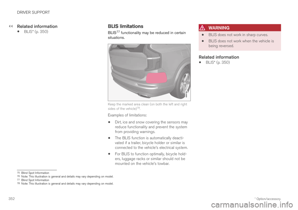
Keep the marked area clean (on both the left and rightsides of the vehicle)78.
Examples of limitations:
Dirt, ice and snow covering the sensors mayreduce functionality and prevent the systemfrom providing warnings.
The BLIS function is automatically deacti-vated if a trailer, bicycle holder or similar isconnected to the vehicle's electrical system.
For BLIS to function optimally, bicycle hold-ers, luggage racks or similar should not bemounted on the vehicle's towbar.
WARNING
BLIS does not work in sharp curves.
BLIS does not work when the vehicle isbeing reversed.
Related information
BLIS* (p. 350)
75Blind Spot Information76Note: This illustration is general and details may vary depending on model.77Blind Spot Information78Note: This illustration is general and details may vary depending on model.
Page 359 of 695

DRIVER SUPPORT
* Option/accessory.357
Examples of further limitations
Dirt, ice and snow covering the sensors mayreduce functionality and prevent the systemfrom providing warnings. For additional infor-mation, see the section "Recommendedmaintenance for Cross Traffic Alert".
CTA is automatically deactivated if a trailer,bicycle holder or similar is connected to thevehicle's electrical system.
For CTA to function optimally, bicycle hold-ers, luggage racks or similar should not bemounted on the vehicle's towbar.
Related information
Cross Traffic Alert* (p. 355)
Recommended maintenance for CrossTraffic Alert (p. 357)
Recommended maintenance forCross Traffic Alert
For optimal performance, it is important tokeep the areas in front of the sensors clean.
Do not attach any objects, tape or decals tothe surface of the sensors.
Keep the marked area clean (on both the left and rightsides of the vehicle)87.
The CTA sensors are located on the inside ofeach of the rear fenders/bumpers and are also
used by the BLIS88 and Rear Collision Warningfunctions.
CAUTION
Repair of BLIS and CTA components orrepainting of the bumper may only be per-formed by a workshop – an authorized Volvoworkshop is recommended.
Related information
Cross Traffic Alert* (p. 355)
BLIS* (p. 350)
Rear Collision Warning (p. 349)
87Note: This illustration is general and details may vary depending on model.88Blind Spot Information
Page 393 of 695
DRIVER SUPPORT
}}
* Option/accessory.391
Park Assist Camera*
The Park Assist Camera can help provide thedriver when maneuvering in tight spaces by alert-ing the driver to obstacles using the camerascreen and graphics in the center display.
The Park Assist Camera is a support functionthat is automatically activated when reverse gearis engaged. It can also be started manually fromthe center display.
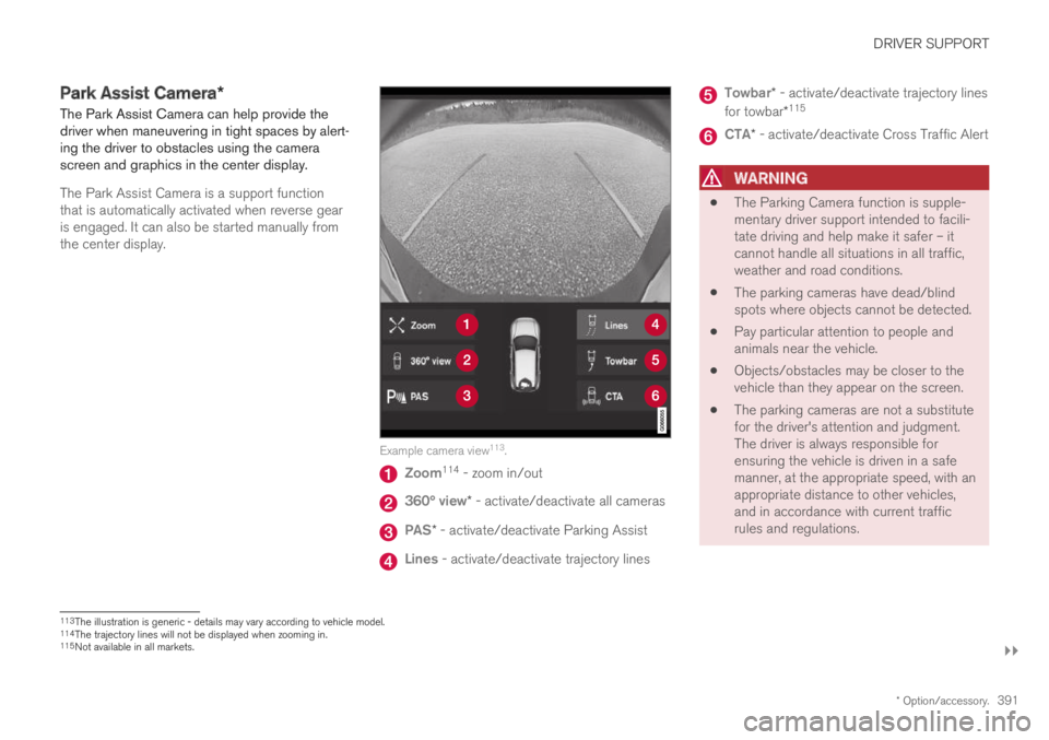
Example camera view113.
Zoom114 - zoom in/out
360° view* - activate/deactivate all cameras
PAS* - activate/deactivate Parking Assist
Lines - activate/deactivate trajectory lines
Towbar* - activate/deactivate trajectory lines
for towbar*115
CTA* - activate/deactivate Cross Traffic Alert
WARNING
The Parking Camera function is supple-mentary driver support intended to facili-tate driving and help make it safer – itcannot handle all situations in all traffic,weather and road conditions.
The parking cameras have dead/blindspots where objects cannot be detected.
Pay particular attention to people andanimals near the vehicle.
Objects/obstacles may be closer to thevehicle than they appear on the screen.
The parking cameras are not a substitutefor the driver's attention and judgment.The driver is always responsible forensuring the vehicle is driven in a safemanner, at the appropriate speed, with anappropriate distance to other vehicles,and in accordance with current trafficrules and regulations.
113The illustration is generic - details may vary according to vehicle model.114The trajectory lines will not be displayed when zooming in.115Not available in all markets.
Page 395 of 695
DRIVER SUPPORT
* Option/accessory.393
Back
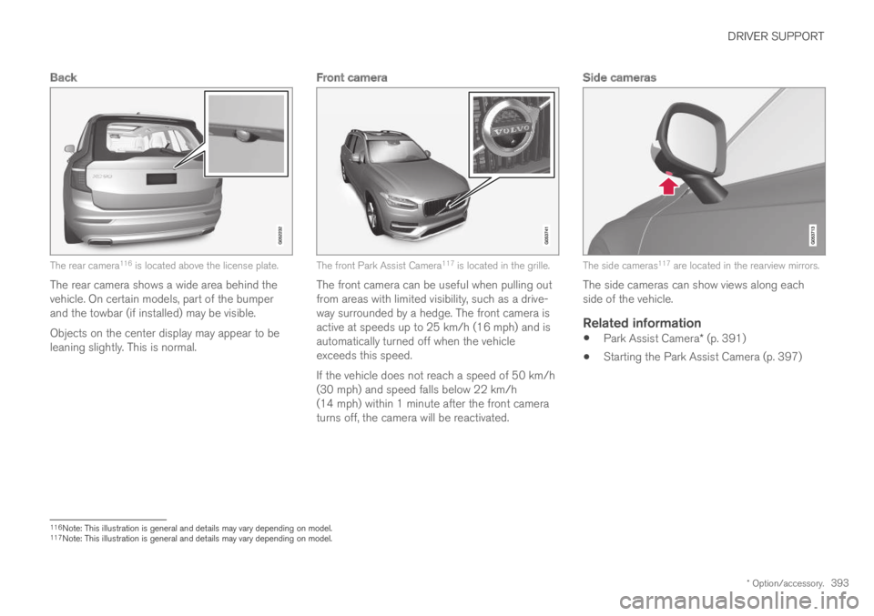
The rear camera116 is located above the license plate.
The rear camera shows a wide area behind thevehicle. On certain models, part of the bumperand the towbar (if installed) may be visible.
Objects on the center display may appear to beleaning slightly. This is normal.
Front camera
The front Park Assist Camera117 is located in the grille.
The front camera can be useful when pulling outfrom areas with limited visibility, such as a drive-way surrounded by a hedge. The front camera isactive at speeds up to 25 km/h (16 mph) and isautomatically turned off when the vehicleexceeds this speed.
If the vehicle does not reach a speed of 50 km/h(30 mph) and speed falls below 22 km/h(14 mph) within 1 minute after the front cameraturns off, the camera will be reactivated.
Side cameras
The side cameras117 are located in the rearview mirrors.
The side cameras can show views along eachside of the vehicle.
Related information
Park Assist Camera* (p. 391)
Starting the Park Assist Camera (p. 397)
116Note: This illustration is general and details may vary depending on model.117Note: This illustration is general and details may vary depending on model.
Page 396 of 695
DRIVER SUPPORT
394
Park Assist Camera trajectory lines
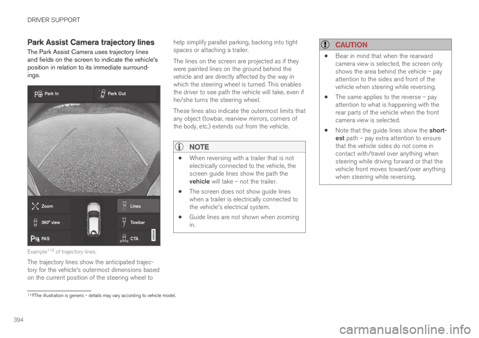
The Park Assist Camera uses trajectory linesand fields on the screen to indicate the vehicle'sposition in relation to its immediate surround-ings.
Example118 of trajectory lines.
The trajectory lines show the anticipated trajec-tory for the vehicle's outermost dimensions basedon the current position of the steering wheel to
help simplify parallel parking, backing into tightspaces or attaching a trailer.
The lines on the screen are projected as if theywere painted lines on the ground behind thevehicle and are directly affected by the way inwhich the steering wheel is turned. This enablesthe driver to see path the vehicle will take, even ifhe/she turns the steering wheel.
These lines also indicate the outermost limits thatany object (towbar, rearview mirrors, corners ofthe body, etc.) extends out from the vehicle.
NOTE
When reversing with a trailer that is notelectrically connected to the vehicle, thescreen guide lines show the path thevehicle will take – not the trailer.
The screen does not show guide lineswhen a trailer is electrically connected tothe vehicle's electrical system.
Guide lines are not shown when zoomingin.
CAUTION
Bear in mind that when the rearwardcamera view is selected, the screen onlyshows the area behind the vehicle – payattention to the sides and front of thevehicle when steering while reversing.
The same applies to the reverse – payattention to what is happening with therear parts of the vehicle when the frontcamera view is selected.
Note that the guide lines show the short-est path – pay extra attention to ensurethat the vehicle sides do not come incontact with/travel over anything whensteering while driving forward or that thevehicle front moves toward/over anythingwhen steering while reversing.
118The illustration is generic - details may vary according to vehicle model.
Page 397 of 695
DRIVER SUPPORT
* Option/accessory.395
Trajectory lines in 360° view *
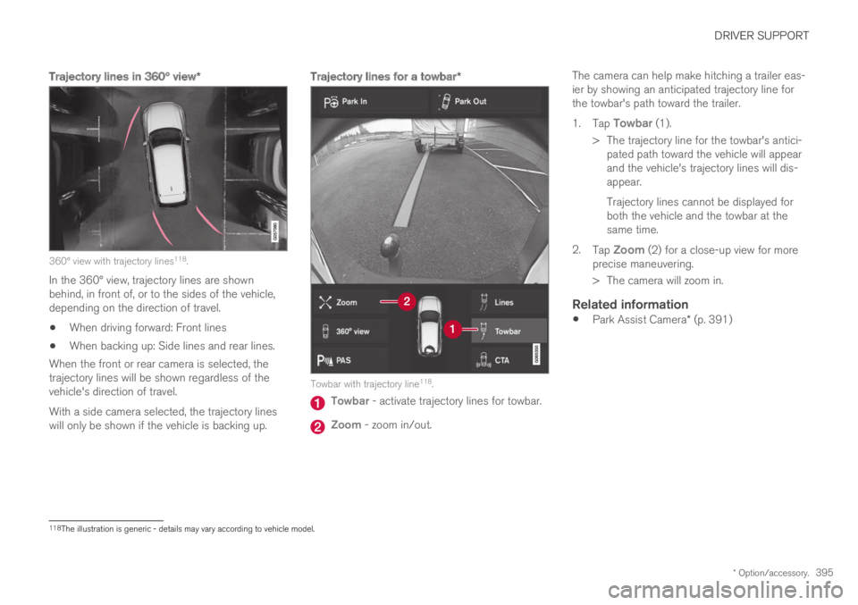
360° view with trajectory lines118.
In the 360° view, trajectory lines are shownbehind, in front of, or to the sides of the vehicle,depending on the direction of travel.
When driving forward: Front lines
When backing up: Side lines and rear lines.
When the front or rear camera is selected, thetrajectory lines will be shown regardless of thevehicle's direction of travel.
With a side camera selected, the trajectory lineswill only be shown if the vehicle is backing up.
Trajectory lines for a towbar *
Towbar with trajectory line118.
Towbar - activate trajectory lines for towbar.
Zoom - zoom in/out.
The camera can help make hitching a trailer eas-ier by showing an anticipated trajectory line forthe towbar's path toward the trailer.
1.Tap Towbar (1).
>The trajectory line for the towbar's antici-pated path toward the vehicle will appearand the vehicle's trajectory lines will dis-appear.
Trajectory lines cannot be displayed forboth the vehicle and the towbar at thesame time.
2.Tap Zoom (2) for a close-up view for moreprecise maneuvering.
>The camera will zoom in.
Related information
Park Assist Camera* (p. 391)
118The illustration is generic - details may vary according to vehicle model.
Page 480 of 695
||
STARTING AND DRIVING
* Option/accessory.478
12. Remove the jumper cables in the reverseorder ‒ first the black cables and then thered cables.
Make sure that none of the clamps of theblack jumper cables come into contact witheither vehicle's positive (+) jump start termi-nals or either of the red jumper cable's con-nected clamps.
WARNING
PROPOSITION 65 WARNING! Battery posts,terminals, and related accessories containlead and lead compounds, chemicals knownto the state of California to cause cancer andreproductive harm. Wash hands after han-dling.
WARNING
Batteries generate hydrogen gas, whichis flammable and explosive.
Do not connect the jumper cable to anypart of the fuel system or to any movingparts. Avoid touching hot manifolds.
Battery fluid contains sulfuric acid. Do notallow battery fluid to contact eyes, skin,fabrics or painted surfaces.
If contact occurs, flush the affected areaimmediately with water. Obtain medicalhelp immediately if eyes are affected.
Never expose the battery to open flameor electric spark. Do not smoke near thebattery. Failure to follow the instructionsfor jump starting can lead to injury.
NOTE
The vehicle cannot be started if the hybridbattery is discharged.
Related information
Starting the vehicle (p. 430)
Ignition modes (p. 433)
Adjusting the steering wheel (p. 198)
Selecting ignition mode (p. 434)
Detachable towbar*
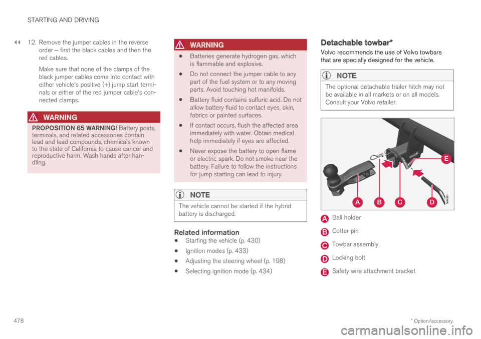
Volvo recommends the use of Volvo towbarsthat are specially designed for the vehicle.
NOTE
The optional detachable trailer hitch may notbe available in all markets or on all models.Consult your Volvo retailer.
Ball holder
Cotter pin
Towbar assembly
Locking bolt
Safety wire attachment bracket
Page 481 of 695
STARTING AND DRIVING
}}
479
Installing the ball holder
1. If necessary, remove the cotter pin from thelocking bolt and slide the locking bolt out ofthe towbar assembly.
2. Slide the ball holder into the towbar assem-bly.
3. Align the hole in the ball holder with the onein the towbar assembly.
4. Slide the locking bolt through the towbarassembly/ball holder.
5. Insert the cotter pin in the hole at the end ofthe locking bolt.
WARNING
Be sure the towbar is securely locked inposition before attaching anything to it.
Always attach the trailer's safety wiresecurely to the towbar's safety wireattachment bracket.
Removing the ball holder
1. Remove the cotter pin from the locking boltand slide the locking bolt out of the ballholder/towbar assembly.
2. Pull the ball holder out of the towbar assem-bly.
Stowing the ball holder
WARNING
When not in use, the detachable ball holdershould always be properly stowed in the des-ignated location under the floor of the cargocompartment.
Related information
Driving with a trailer (p. 479)
Towing capacity and tongue weight (p. 668)
Driving with a trailer
There are a number of things to consider whentowing a trailer, such as the towbar, the trailerand how the load is distributed in the trailer.
Load-carrying capacity is determined by the vehi-cle's curb weight. The total weight of all passen-gers and any installed accessories, e.g. towbar,reduces the vehicle's load-carrying capacity bythe corresponding amount.
Towbars used on the vehicle must beapproved for the applicable use.
Distribute the load on the trailer so that theweight on the towbar complies with thespecified maximum towball weight. Thetongue weight is calculated as part of thevehicle's payload.
Increase the tire pressure to the recom-mended pressure for a full load.
The engine is subjected to more load thanusual when towing a trailer.
Towing a trailer affects the vehicle's han-dling, durability and driving economy.
Do not drive with a heavy trailer when thevehicle is very new. Wait until the mileagehas reached at least 1000 km (620 miles).
On long and steep downgrades, the vehicle'sbrakes are subjected to much more loadthan usual. When manually shifting, down-shift and adapt speed accordingly.