warning VOLVO XC60 TWIN ENGINE 2020 Service Manual
[x] Cancel search | Manufacturer: VOLVO, Model Year: 2020, Model line: XC60 TWIN ENGINE, Model: VOLVO XC60 TWIN ENGINE 2020Pages: 687, PDF Size: 14.65 MB
Page 77 of 687

SAFETY
}}
75
Top tether anchors
Your Volvo is equipped with child restraint top tether anchorages for all three seatingpositions in the rear seat. They are located onthe rear side of the backrests.
Child restraint anchorages
Top tether anchors and symbols on the rear side of the rear seat backrests. There is no symbol for thecenter anchor position.
Securing a child seat
1. Place the child restraint on the rear seat.
2. Route the top tether strap under the head restraint and attach it to the anchor. 3. Attach the strap for the lower tether
anchors in the lower ISOFIX/LATCH attachment points. If the child restraint isnot equipped with straps for the lowertether anchors, or if the child restraint isused on the center seating position, followthe instructions for attaching a childrestraint using the automatic locking seatbelt.
4. Firmly tension all straps. Refer also to the child seat manufacturer's instructions for information on securing thechild seat.
NOTE
If the vehicle is equipped with a cargo compartment cover, this must be removedbefore a child seat can be attached in thetether anchors.
WARNING
Always refer to the recommendations made by the child restraint manufac-turer.
Volvo recommends that the top tetheranchors be used when installing a for-ward-facing child restraint.
Never route a top tether strap over thetop of the head restraint. The strapshould be routed beneath the headrestraint.
Child restraint anchorages aredesigned to withstand only those loadsimposed by correctly fitted childrestraints. Under no circumstances arethey to be used for adult seat belts orharnesses. The anchorages are not ableto withstand excessive forces on themin the event of collision if full harnessseat belts or adult seat belts are instal-led to them. An adult who uses a beltanchored in a child restraint anchorageruns a great risk of suffering severeinjuries should a collision occur.
Do not install rear speakers that requirethe removal of the top tether anchorsor interfere with the proper use of thetop tether strap.
Page 79 of 687
SAFETY
}}
77
ISOFIX/LATCH lower anchors
Lower anchors for ISOFIX/LATCH-equipped child seats are located in the rear, outboard seats, hidden below the backrest cushions.
Using the ISOFIX/LATCH lower child seat anchors
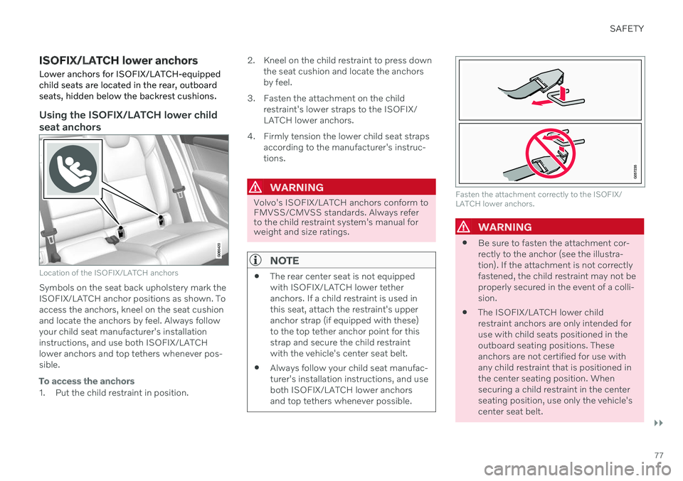
Location of the ISOFIX/LATCH anchors
Symbols on the seat back upholstery mark the ISOFIX/LATCH anchor positions as shown. Toaccess the anchors, kneel on the seat cushionand locate the anchors by feel. Always followyour child seat manufacturer's installationinstructions, and use both ISOFIX/LATCHlower anchors and top tethers whenever pos-sible.
To access the anchors
1. Put the child restraint in position. 2. Kneel on the child restraint to press down
the seat cushion and locate the anchors by feel.
3. Fasten the attachment on the child restraint's lower straps to the ISOFIX/LATCH lower anchors.
4. Firmly tension the lower child seat straps according to the manufacturer's instruc-tions.
WARNING
Volvo's ISOFIX/LATCH anchors conform to FMVSS/CMVSS standards. Always referto the child restraint system's manual forweight and size ratings.
NOTE
The rear center seat is not equipped with ISOFIX/LATCH lower tetheranchors. If a child restraint is used inthis seat, attach the restraint's upperanchor strap (if equipped with these)to the top tether anchor point for thisstrap and secure the child restraintwith the vehicle's center seat belt.
Always follow your child seat manufac-turer's installation instructions, and useboth ISOFIX/LATCH lower anchorsand top tethers whenever possible.
Fasten the attachment correctly to the ISOFIX/ LATCH lower anchors.
WARNING
Be sure to fasten the attachment cor- rectly to the anchor (see the illustra-tion). If the attachment is not correctlyfastened, the child restraint may not beproperly secured in the event of a colli-sion.
The ISOFIX/LATCH lower childrestraint anchors are only intended foruse with child seats positioned in theoutboard seating positions. Theseanchors are not certified for use withany child restraint that is positioned inthe center seating position. Whensecuring a child restraint in the centerseating position, use only the vehicle'scenter seat belt.
Page 81 of 687
SAFETY
* Option/accessory.79
Canadian models
Stage 1 Stage 2
Weight 22 - 36 kg 50 - 80 lbs 18 - 25 kg 40 - 55 lbs
Length 115 - 140 cm 45 - 55 in. 102 - 120 cm40 - 47 in.
18 kg (40 lbs) is the minimum weight require- ment for a child using booster seats accordingto the Canadian regulation CMVSS 213.4.
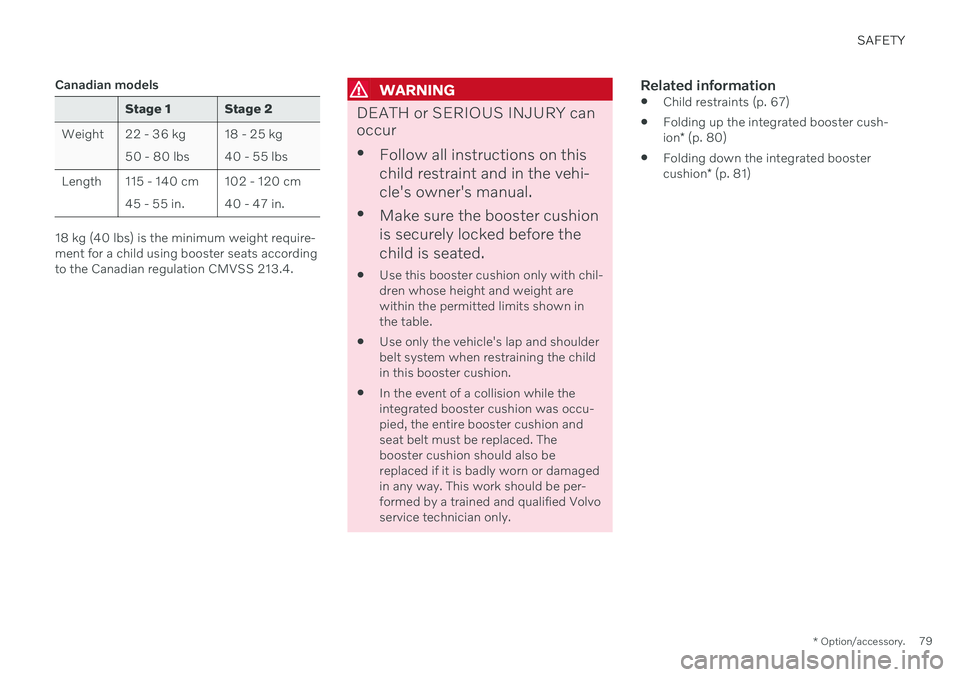
WARNING
DEATH or SERIOUS INJURY can occur
Follow all instructions on this child restraint and in the vehi-cle's owner's manual.
Make sure the booster cushionis securely locked before thechild is seated.
Use this booster cushion only with chil- dren whose height and weight arewithin the permitted limits shown inthe table.
Use only the vehicle's lap and shoulderbelt system when restraining the childin this booster cushion.
In the event of a collision while theintegrated booster cushion was occu-pied, the entire booster cushion andseat belt must be replaced. Thebooster cushion should also bereplaced if it is badly worn or damagedin any way. This work should be per-formed by a trained and qualified Volvoservice technician only.
Related information
Child restraints (p. 67)
Folding up the integrated booster cush- ion
* (p. 80)
Folding down the integrated boostercushion
* (p. 81)
Page 83 of 687

SAFETY
}}
* Option/accessory.81
WARNING
DEATH or SERIOUS INJURY can occur
Follow all instructions on this child restraint and in the vehi-cle's owner's manual.
Make sure the booster cushionis securely locked before thechild is seated.
Use this booster cushion only with chil- dren whose height and weight arewithin the permitted limits shown inthe table.
Use only the vehicle's lap and shoulderbelt system when restraining the childin this booster cushion.
In the event of a collision while theintegrated booster cushion was occu-pied, the entire booster cushion andseat belt must be replaced. Thebooster cushion should also bereplaced if it is badly worn or damagedin any way. This work should be per-formed by a trained and qualified Volvoservice technician only.
NOTE
The integrated booster cushion cannot be moved directly from the upper position tothe lower position. From the upper posi-tion, the booster cushion must first befolded down completely into the rear seatand then raised to the lower position.
Related information
Integrated booster cushion
* (p. 78)
Folding down the integrated booster cushion
* (p. 81)
Folding down the integrated booster cushion *
When the integrated booster cushion in the rear seat is not in use, it should be stowed(folded down).
NOTE
The integrated booster cushion cannot be moved directly from the upper position tothe lower position. From the upper posi-tion, the booster cushion must first befolded down completely into the rear seatand then raised to the lower position.
Pull the handle forward to release the booster cushion.
Page 84 of 687
||
SAFETY
* Option/accessory.
82
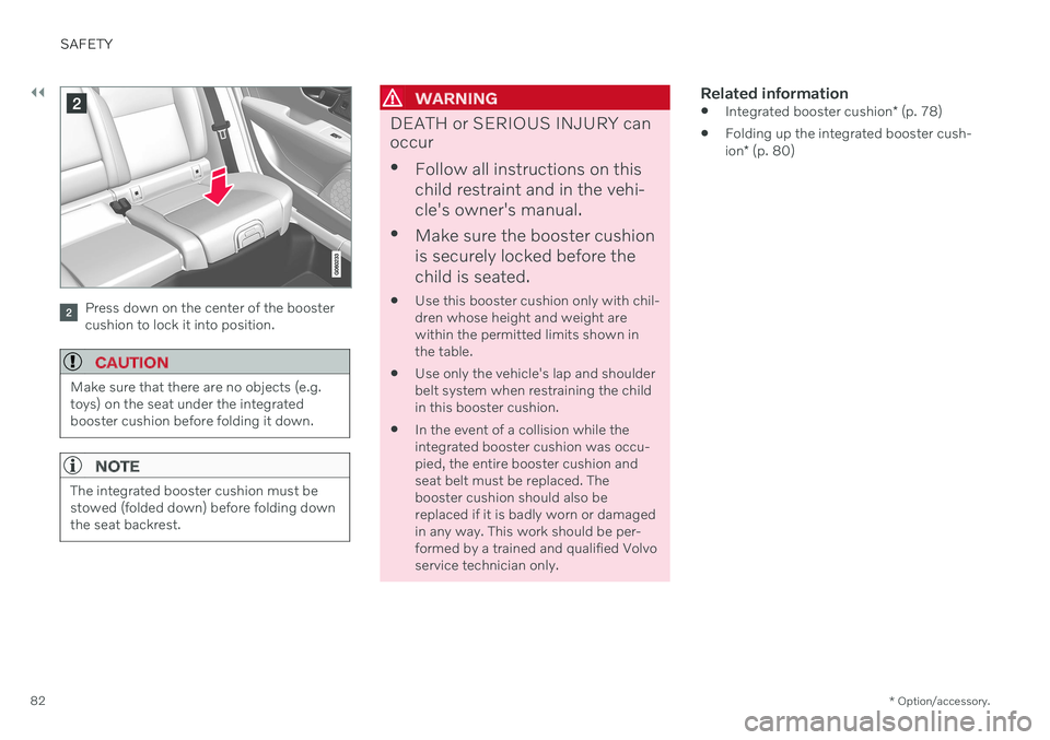
Press down on the center of the booster cushion to lock it into position.
CAUTION
Make sure that there are no objects (e.g. toys) on the seat under the integratedbooster cushion before folding it down.
NOTE
The integrated booster cushion must be stowed (folded down) before folding downthe seat backrest.
WARNING
DEATH or SERIOUS INJURY can occur
Follow all instructions on this child restraint and in the vehi-cle's owner's manual.
Make sure the booster cushionis securely locked before thechild is seated.
Use this booster cushion only with chil- dren whose height and weight arewithin the permitted limits shown inthe table.
Use only the vehicle's lap and shoulderbelt system when restraining the childin this booster cushion.
In the event of a collision while theintegrated booster cushion was occu-pied, the entire booster cushion andseat belt must be replaced. Thebooster cushion should also bereplaced if it is badly worn or damagedin any way. This work should be per-formed by a trained and qualified Volvoservice technician only.
Related information
Integrated booster cushion
* (p. 78)
Folding up the integrated booster cush- ion
* (p. 80)
Page 86 of 687
DISPLAYS AND VOICE CONTROL
* Option/accessory.
84
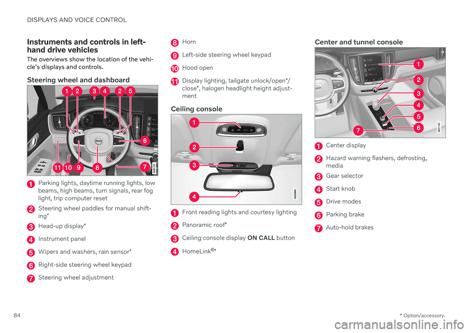
Instruments and controls in left- hand drive vehicles The overviews show the location of the vehi- cle's displays and controls.
Steering wheel and dashboard
Parking lights, daytime running lights, low beams, high beams, turn signals, rear foglight, trip computer reset
Steering wheel paddles for manual shift- ing *
Head-up display *
Instrument panel
Wipers and washers, rain sensor *
Right-side steering wheel keypad
Steering wheel adjustment
Horn
Left-side steering wheel keypad
Hood open
Display lighting, tailgate unlock/open */
close *, halogen headlight height adjust-
ment
Ceiling console
Front reading lights and courtesy lighting
Panoramic roof *
Ceiling console display ON CALL button
HomeLink ®
*
Center and tunnel console
Center display
Hazard warning flashers, defrosting, media
Gear selector
Start knob
Drive modes
Parking brake
Auto-hold brakes
Page 88 of 687

DISPLAYS AND VOICE CONTROL
* Option/accessory.
86
Instrument panel The instrument panel displays information related to the vehicle and driving.
The instrument panel contains gauges, indica- tors and monitoring and warning symbols.What is shown in the instrument panel variesdepending on the equipment, settings andfunctions currently active. The instrument panel is activated as soon as a door is opened, i.e. in ignition mode 0. The
panel will power down after a short period oftime if it is not used. To reactivate it, do one ofthe following:
Depress the brake pedal.
Activate ignition mode
I.
Open one of the doors.
WARNING
If the instrument panel turns off, does not activate when the ignition is switched on,or part/all of the panel cannot be read, donot drive the vehicle. Consult a workshopimmediately. Volvo recommends anauthorized Volvo workshop.
WARNING
If the instrument panel is not functioning properly, information about brakes, airbagsor other safety-related systems may not bedisplayed. The driver will then not be ableto check the status of the vehicle systemsor receive relevant warnings and informa-tion.
The illustration is generic - details may vary accord- ing to vehicle model.
Location in the instrument panel:
Left side In the center Right side
Speedometer Indicator and warning symbols
Tachometer/Hybrid gaugeA
Trip odometer Ambient temperature sensor Gear indicator Odometer B
Clock Drive Mode
Cruise control/speed limiter information Message (also graphics in some cases) Fuel gauge Road sign information * Door and seat belt status Hybrid battery gauge
– Hybrid battery's charge level Distance to empty tank
Page 89 of 687
DISPLAYS AND VOICE CONTROL
* Option/accessory.87
Left side In the center Right side – Media player Distance to discharged battery
– Navigation system map*Current fuel consumption
– PhoneApp menu (activated using steering wheel keypad)
– Voice Control –
– CompassA
–
ADepends on selected drive mode.
B Total distance.
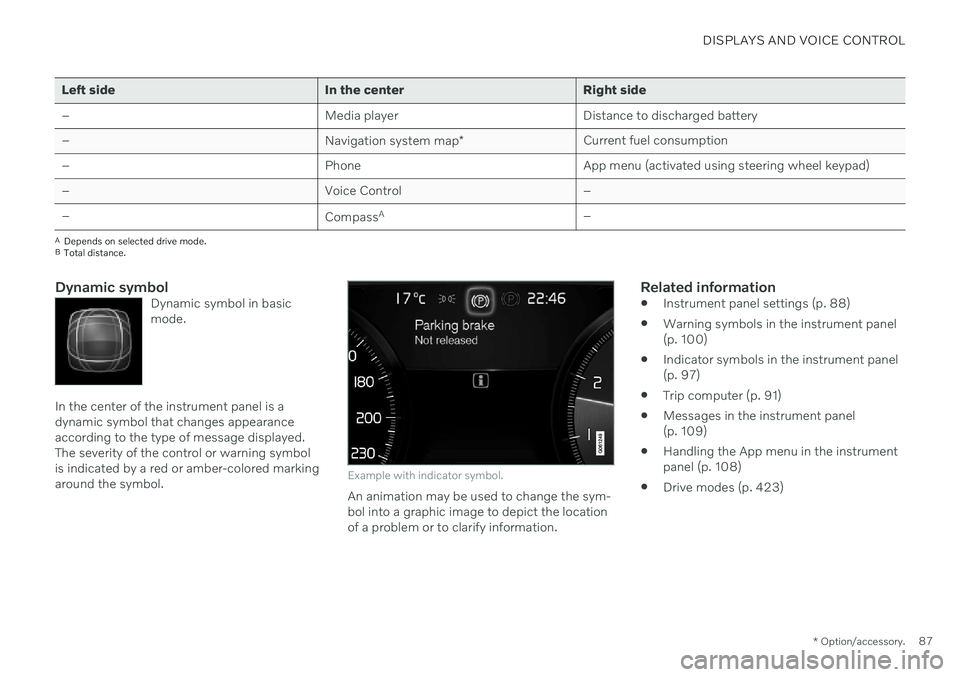
Dynamic symbolDynamic symbol in basic mode.
In the center of the instrument panel is a dynamic symbol that changes appearanceaccording to the type of message displayed.The severity of the control or warning symbolis indicated by a red or amber-colored markingaround the symbol.
Example with indicator symbol.
An animation may be used to change the sym- bol into a graphic image to depict the locationof a problem or to clarify information.
Related information
Instrument panel settings (p. 88)
Warning symbols in the instrument panel(p. 100)
Indicator symbols in the instrument panel(p. 97)
Trip computer (p. 91)
Messages in the instrument panel(p. 109)
Handling the App menu in the instrumentpanel (p. 108)
Drive modes (p. 423)
Page 101 of 687

DISPLAYS AND VOICE CONTROL
99
Symbol Meaning
Stability system This symbol flashes when the stability system is actively work-ing to stabilize the vehicle. If thesymbol glows steadily, there is afault in the system.
Stability system, Sport mode This symbol illuminates when Sport mode is activated. Sportmode offers a more active drivingexperience. If the system detectsthat accelerator pedal, steeringwheel and cornering movementsare more active than in normaldriving, it allows a certain level ofcontrolled lateral movement ofthe rear wheels before interven-ing and stabilizing the vehicle.
Symbol Meaning
Lane Keeping Aid White symbol: Lane Keeping Aid is on and lane marker lines aredetected. Gray symbol: Lane Keeping Aid is on but no lane marker lines aredetected. Amber-colored symbol: Lane Keeping Aid is alerting/interven-ing.
Lane Keeping Aid and rain sen- sor White symbol: Lane Keeping Aid is on and lane marker lines aredetected. The rain sensor is on. Gray symbol: Lane Keeping Aid is on but no lane marker lines aredetected. The rain sensor is on.
Reduced performance In the event of a temporary fault in the driveline, the vehicle maygo into a "limp home" mode withreduced power output to helpavoid damage to the driveline.
ACanadian models.
B US models.
Related information
Instrument panel (p. 86)
Warning symbols in the instrument panel (p. 100)
Page 102 of 687

DISPLAYS AND VOICE CONTROL
100
Warning symbols in the instrument panelThe warning symbols alert the driver that an important function is activated or that a seri-ous fault or error has occurred.
Symbol Meaning
WARNING The red warning symbol illumi- nates to indicate that a fault hasbeen detected that could affectsafety or driveability. An explana-tory message will be simultane-ously displayed in the instrumentpanel. The warning symbol mayalso illuminate in combinationwith other symbols.
Seat belt reminder This symbol will glow steadily or flash if the driver or front seatpassenger has not fastened theirseat belt or if anyone in the rearseat has removed their seat belt.
Symbol Meaning
Airbags If this symbol remains illumi- nated or comes on while driving,a fault has been detected in oneof the vehicle's safety systems.Read the message in the instru-ment panel. Volvo recommendscontacting an authorized Volvoworkshop.
A
B Fault in brake system If this symbol illuminates, the brake fluid level may be too low.Contact your nearest authorizedworkshop to have the brake fluidlevel checked and adjusted.
Symbol Meaning
A
B
Parking brake on This symbol glows steadily when the parking brake is applied. A flashing symbol indicates that a fault has occurred. Read themessage in the instrument panel.
Low oil pressure If this symbol illuminates while driving when the engine oil pres-sure is too low. Stop the engineimmediately and check theengine oil level. Add oil if neces-sary. If the symbol illuminatesand the oil level is normal, con-tact a workshop. Volvo recom-mends contacting an authorizedVolvo workshop.
Generator not charging This symbol illuminates during driving if a fault is detected in theelectrical system. Contact aworkshop. Volvo recommendscontacting an authorized Volvoworkshop.