engine VOLVO XC70 2003 Manual PDF
[x] Cancel search | Manufacturer: VOLVO, Model Year: 2003, Model line: XC70, Model: VOLVO XC70 2003Pages: 257, PDF Size: 5.33 MB
Page 198 of 257
2003 VOLVO XC70
l Check the fluid level in each cell in the battery every 24 months or eve\
ry 15,000* miles (24,000 km),
whichever is sooner. The fluid should be at the level shown in the illus\
tration above (A**).
Use a screwdriver to open the caps and a flashlight to inspect the level\
.
l If necessary, add distilled water. The level should never be above the indicator (A).
l The fluid level should be checked if the battery has been recharged.
l After inspection, be sure the cap over each battery cell is securely in \
place.
l Check that the battery cables are correctly connected and properly tight\
ened.
l Never disconnect the battery when the engine is running, for example whe\
n changing the battery.
l The battery should be disconnected from the vehicle when a battery charg\
er is used directly on the
battery. However, if the battery is being charged via the connecting poi\
nts in the engine compartment
(see
page 101), the battery must be connected.
PROPOSITION 65 WARNING!
Battery posts, terminals, and related accessories contain lead and lead \
compounds, chemicals known
to the state of California to cause cancer and reproductive harm. Wash h\
ands after handling.
* More frequently in warm climates.
** The level indicator inside the battery could be designed in various w\
ays. See illustration above!
Battery warning symbols Battery warning symbols
file:///K|/ownersdocs/2003/2003_XC70/03xc70_08b.htm (12 of 16)12/30/20\
06 4:18:04 PM
Page 203 of 257
2003 VOLVO XC70
2 0 0 3
VOLVO XC70
Chapter 9 - Specifications
pg. 141 Specifications
Label information 142
Dimensions and weights 143
Engine specifications 144
Transmission specifications 145
Oil/fluid specifications and volumes 146
Fuel system, Distributor ignition system,
Suspension 147
Electrical system 148
Volvo On Call 149
pg. 142 Label information
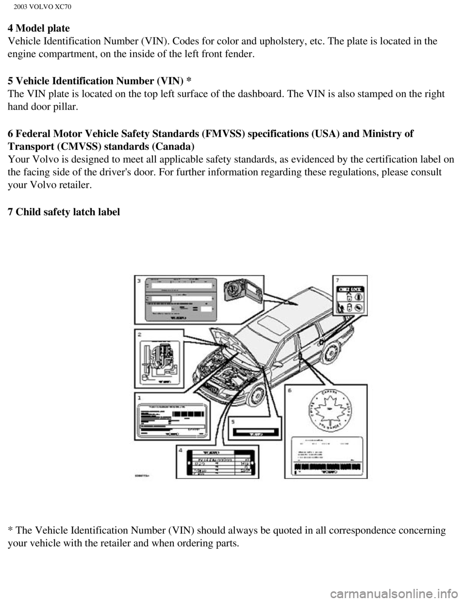
1 Vehicle Emission Control Information
Your Volvo is designed to meet all applicable emission standards, as evi\
denced by the certification label
on the underside of the hood. For further information regarding these re\
gulations, please consult your
Volvo retailer.
2 Vacuum hose routing
(underside of hood)
3 Loads and Tire Pressures
(on inside of fuel filler door)
file:///K|/ownersdocs/2003/2003_XC70/03xc70_09.htm (1 of 11)12/30/2006\
4:18:05 PM
Page 204 of 257
2003 VOLVO XC70
4 Model plate
Vehicle Identification Number (VIN). Codes for color and upholstery, e\
tc. The plate is located in the
engine compartment, on the inside of the left front fender.
5 Vehicle Identification Number (VIN) *
The VIN plate is located on the top left surface of the dashboard. The V\
IN is also stamped on the right
hand door pillar.
6 Federal Motor Vehicle Safety Standards (FMVSS) specifications (USA)\
and Ministry of
Transport (CMVSS) standards (Canada)
Your Volvo is designed to meet all applicable safety standards, as evide\
nced by the certification label on
the facing side of the driver's door. For further information regarding \
these regulations, please consult
your Volvo retailer.
7 Child safety latch label
* The Vehicle Identification Number (VIN) should always be quoted in a\
ll correspondence concerning
your vehicle with the retailer and when ordering parts.
file:///K|/ownersdocs/2003/2003_XC70/03xc70_09.htm (2 of 11)12/30/2006\
4:18:05 PM
Page 206 of 257

2003 VOLVO XC70
Gross vehicle weight (GVW)
V70 man. 4630 lbs 2100 kg
V70 aut. 4690 lbs 2130 kg
V70 Turbo man. 4670 lbs 2120 kg
V70 Turbo aut. 4730 lbs 2150 kg
V70 AWD 4890 lbs 2220 kg
XC70 4890 lbs 2220 kg
Capacity weight
*** 930 lbs
420 kg
Curb weight
V70 3390-3585
lbs 1541-1632 kg
V70 AWD 3690-3725
lbs 1675-1695 kg
XC70 3765-3800
lbs 1710-1730 kg
Permissible axle weight, front
V70 man. 2290 lbs 1040 kg
V70 aut. 2330 lbs 1060 kg
V70 Turbo aut. 2400 lbs 1090 kg
V70 AWD 2400 lbs 1090 kg
XC70 2490 lbs 1130 kg
Permissible axle weight, rear
V70, V70 Turbo 2470 lbs 1120 kg
V70 AWD 2580 lbs 1170 kg
XC70 2620 lbs 1190 kg
* When driving for prolonged periods at temperatures above 86° F (30\
° C), the maximum recommended
weight is 2000 lbs (900 kg).
**See also section "Trailer towing"
*** The max permissible axle loads or the gross vehicle weight must not \
be exceeded.
All specifications are subject to change without prior notice.
pg. 144 Engine specifications
file:///K|/ownersdocs/2003/2003_XC70/03xc70_09.htm (4 of 11)12/30/2006\
4:18:05 PM
Page 207 of 257

2003 VOLVO XC70
Engine specifications
Designation: Volvo B 5234 T3
Output 247 hp at 5200 rpm (184 kW/87 rps)
Max. torque 243 ft. lbs. at 2400-5200 rpm (330 Nm/42-87
rps)
Number of
cylinders 5
Bore 3.19" (81 mm)
Stroke 3.54" (90 mm)
Displacement 2.3 liters
Compression ratio 8.5:1
Number of valves 20
Designation: Volvo B 5254 T2
Output 208 hp at 5000 rpm (154 kW/83 rps)
Max. torque 236 ft. lbs. at 1500-4500 rpm (320 Nm/25-75
rps)
Number of
cylinders 5
Bore 3.27" (83 mm)
Stroke 3.67" (93.2 mm)
Displacement 2.5 liters
Compression ratio 9.0:1
Number of valves 20
Designation: Volvo B 5244 T3
Output 197 hp at 6000 rpm (147 kW/100 rps)
Max. torque 210 ft. lbs. at 1800-5000 rpm (285 Nm/30-83
rps)
Number of
cylinders 5
Bore 3.27" (83 mm)
Stroke 3.54" (90 mm)
file:///K|/ownersdocs/2003/2003_XC70/03xc70_09.htm (5 of 11)12/30/2006\
4:18:05 PM
Page 208 of 257
2003 VOLVO XC70
Displacement 2.4 liters
Compression ratio 9.0:1
Number of valves 20
Designation: Volvo B 5244 S
Output 168 hp at 6000 rpm (125 kW/100 rps)
Max. torque 166 ft. lbs. at 4500 rpm (225 Nm/75
rps)
Number of
cylinders 5
Bore 3.27" (83 mm)
Stroke 3.54" (90 mm)
Displacement 2.4 liters
Compression ratio 10.3:1
Number of valves 20
Charge air cooler (Intercooler)
Turbocharged engines employ a turbo-compressor to force air into the eng\
ine inlet manifold and a
charge air cooler to cool the compressed inlet air. The resulting increa\
se in air flow raises pressure in the
intake manifold and increases engine power over that developed by A norm\
ally-aspirated engine. The
charge air cooler (which resembles a radiator) is located between the \
turbo-compressor and inlet
manifold.
pg. 145 Transmission specifications
Power transmission
Manual transmission: M 56 LK
Single-disc dry plate clutch. All-synchromesh on all gears including rev\
erse; integrated final drive.
Operation via a floor mounted gear lever.
Final drive ratio 4.00:1
Reduction ratios
1st gear 3.39:1
2nd gear 1.91:1
3rd gear 1.19:1
4th gear 0.87:1
5th gear 0.70:1
file:///K|/ownersdocs/2003/2003_XC70/03xc70_09.htm (6 of 11)12/30/2006\
4:18:05 PM
Page 209 of 257
2003 VOLVO XC70
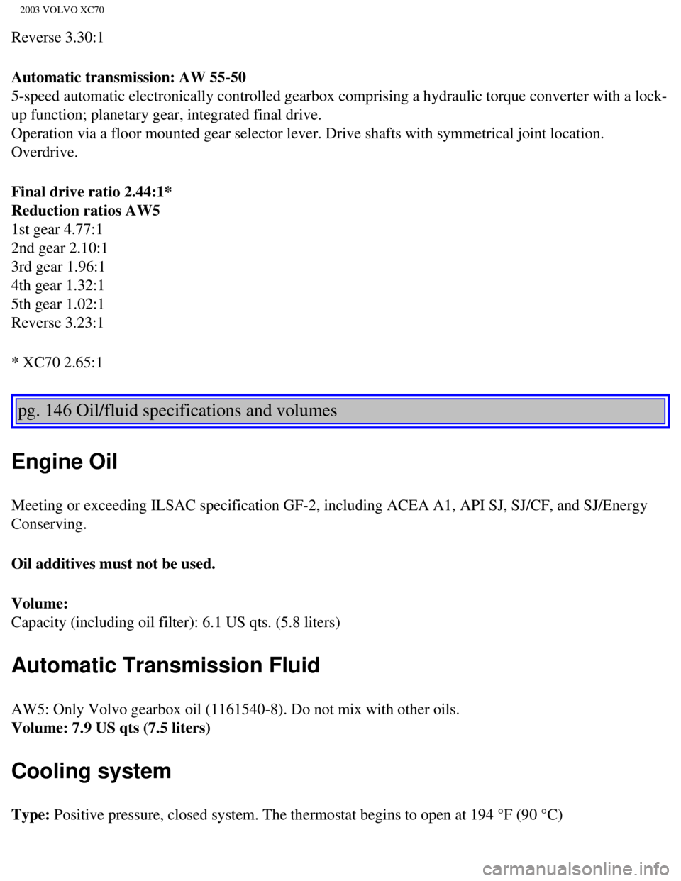
Reverse 3.30:1
Automatic transmission: AW 55-50
5-speed automatic electronically controlled gearbox comprising a hydraul\
ic torque converter with a lock-
up function; planetary gear, integrated final drive.
Operation via a floor mounted gear selector lever. Drive shafts with sym\
metrical joint location.
Overdrive.
Final drive ratio 2.44:1*
Reduction ratios AW5
1st gear 4.77:1
2nd gear 2.10:1
3rd gear 1.96:1
4th gear 1.32:1
5th gear 1.02:1
Reverse 3.23:1
* XC70 2.65:1
pg. 146 Oil/fluid specifications and volumes
Engine Oil
Meeting or exceeding ILSAC specification GF-2, including ACEA A1, API SJ\
, SJ/CF, and SJ/Energy
Conserving.
Oil additives must not be used.
Volume:
Capacity (including oil filter): 6.1 US qts. (5.8 liters)
Automatic Transmission Fluid
AW5: Only Volvo gearbox oil (1161540-8). Do not mix with other oils. \
Volume: 7.9 US qts (7.5 liters)
Cooling system
Type: Positive pressure, closed system. The thermostat begins to open at 194 \
°F (90 °C)
file:///K|/ownersdocs/2003/2003_XC70/03xc70_09.htm (7 of 11)12/30/2006\
4:18:05 PM
Page 210 of 257

2003 VOLVO XC70
Coolant: Volvo original coolant/antifreeze
All specifications are subject to change without prior notice.
Power steering fluid
ATF fluid
Volume: 0.95 US qts (0.9 liters)
Brake fluid
DOT 4+ boiling point >536°F(280°C), P/N 9437433
Volume: 0.64 US qts (0.6 liters)
Climate control system - refrigerant (R 134a)
Oil: PAG
Volume: 2.2 lbs (1,000 g) R134a
Fuel
Minimum octane requirement - AKI 87 (RON 91)
Volume (fuel tank): 18.5 US gals (70 liters) or 19 US gals (72 liters) on models equippe\
d with All
Wheel Drive.
Washer fluid reservoir
Volume: 4.7 US qts (4.5 liters)
All specifications are subject to change without prior notice.
pg. 147 Fuel system, Distributor ignition system, Suspension
Fuel system
The engine is equipped with a multiport fuel injection system.
file:///K|/ownersdocs/2003/2003_XC70/03xc70_09.htm (8 of 11)12/30/2006\
4:18:05 PM
Page 211 of 257

2003 VOLVO XC70
Distributor ignition system
Firing order: 1-2-4-5-3
Electronic ignition setting: Not adjustable
Spark plugs: Champion RC8PYP 8 (or equivalent)
Spark plug gap: 0.028-0.032" (0.7-0.8 mm)
Tightening torque: 18.4 ft. lbs. (25 Nm) WARNING!
The ignition system operates at very high voltages. Special safety preca\
utions must be followed to
prevent injury. Always turn the ignition off when:
l Replacing ignition components e.g. plugs, coil, etc.
l Do not touch any part of the ignition system while the engine is running\
. This may result in a shock
and bodily injury.
Front suspension
Spring strut suspension with integrated shock absorbers and control arms\
linked to the support frame.
Power-assisted rack and pinion steering. Safety type steering column. Th\
e alignment specifications
apply to an unladen car but include fuel, coolant and spare wheel.
Rear suspension
Individual rear wheel suspension with longitudinal support arms, double \
link arms and track rods.
All specifications are subject to change without prior notice.
pg. 148 Electrical system
Electrical system
12 Volt, negative ground.
Voltage-controlled generator. Single-wire system with chassis and engine\
used as conductors. Grounded
on chassis.
Battery
file:///K|/ownersdocs/2003/2003_XC70/03xc70_09.htm (9 of 11)12/30/2006\
4:18:05 PM
Page 239 of 257

2003 VOLVO XC70
your hand-held transmitter's button at two-second intervals until HomeLi\
nk® has learned your
transmitter's code. The HomeLink® indicator light will flash first sl\
owly, and then rapidly to indicate
that the button has been successfully programmed.
Determining if your garage door uses a rolling code
Determine, in one of the following ways, if your garage door uses a roll\
ing code system and is
manufactured after 1996:
l Refer to the garage door opener owner's manual for verification.
l If your hand-held transmitter appears to program the HomeLink® Univer\
sal Transceiver but the
programmed button does not activate the garage door, your garage door op\
ener may have a rolling code.
l Press the programmed HomeLink® button. If the garage door opener has \
the rolling code feature, the
HomeLink® indicator light flashes rapidly and then glows steadily aft\
er approximately 2 seconds.
To train a rolling code garage door opener, follow these instructions after programming the desired
transceiver button according to "Programming the transceiver." The help \
of a second person may make
training easier.
1. Locate the training button on the garage door opener motor head unit. The location and color of the
training button may vary. If you encounter difficulty, refer to the gara\
ge door opener owner's manual or
call toll-free 1-800-355-3515 (Internet:
www.HomeLink.com).
2. Press the "training" button on the garage door opener motor head unit\
until the "training" light comes
on.
3. Press and release the programmed HomeLink® button. Press and relea\
se the programmed
HomeLink® button a second time to complete the training process. Some garage door openers may
require you to do this procedure a third time to complete the training.
The programmed button on your HomeLink® Universal Transceiver should \
now operate your garage
door opener. The original hand-held transmitter can also be used, as des\
ired, to operate the garage door.
The remaining two HomeLink® buttons can be programmed in the same way\
. In the event of any
problems in programming the HomeLink® Universal Transceiver, call tol\
l-free 1-800-355-3515
(Internet:
www.HomeLink.com).
Operating the HomeLink® Universal Transceiver
Once programmed, the HomeLink® Universal Transceiver can be used in p\
lace of your hand-held
transmitters.
To operate, the key must be turned to the "accessory" position (II) or\
the engine must be running. Press
the programmed HomeLink® button to activate the garage door, driveway\
gate, security lighting, home
file:///K|/ownersdocs/2003/2003_XC70/03xc70_11.htm (3 of 5)12/30/2006 \
4:18:07 PM