battery VOLVO XC70 2013 Owner´s Manual
[x] Cancel search | Manufacturer: VOLVO, Model Year: 2013, Model line: XC70, Model: VOLVO XC70 2013Pages: 382, PDF Size: 6.78 MB
Page 259 of 382
06 Infotainment
Rear Seat Entertainment (RSE)*
06
* Option/accessory, for more information, see Introduction.257
NOTE
The headphones will switch off automati-
cally after approx. 3 minutes if they are not
used.
Replacing batteries in the headphonesThe headphones use two AAA batteries.
It is advisable to have extra batteries on hand
during long trips.
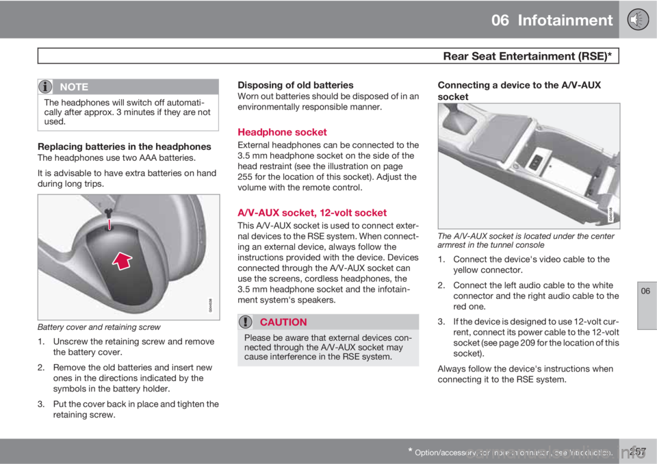
Battery cover and retaining screw
1. Unscrew the retaining screw and remove
the battery cover.
2. Remove the old batteries and insert new
ones in the directions indicated by the
symbols in the battery holder.
3. Put the cover back in place and tighten the
retaining screw.
Disposing of old batteriesWorn out batteries should be disposed of in an
environmentally responsible manner.
Headphone socket
External headphones can be connected to the
3.5 mm headphone socket on the side of the
head restraint (see the illustration on page
255 for the location of this socket). Adjust the
volume with the remote control.
A/V-AUX socket, 12-volt socket
This A/V-AUX socket is used to connect exter-
nal devices to the RSE system. When connect-
ing an external device, always follow the
instructions provided with the device. Devices
connected through the A/V-AUX socket can
use the screens, cordless headphones, the
3.5 mm headphone socket and the infotain-
ment system's speakers.
CAUTION
Please be aware that external devices con-
nected through the A/V-AUX socket may
cause interference in the RSE system.
Connecting a device to the A/V-AUX
socket
The A/V-AUX socket is located under the center
armrest in the tunnel console
1. Connect the device's video cable to the
yellow connector.
2. Connect the left audio cable to the white
connector and the right audio cable to the
red one.
3. If the device is designed to use 12-volt cur-
rent, connect its power cable to the 12-volt
socket (see page 209 for the location of this
socket).
Always follow the device's instructions when
connecting it to the RSE system.
Page 267 of 382
06 Infotainment
Remote control*
06
* Option/accessory, for more information, see Introduction.265
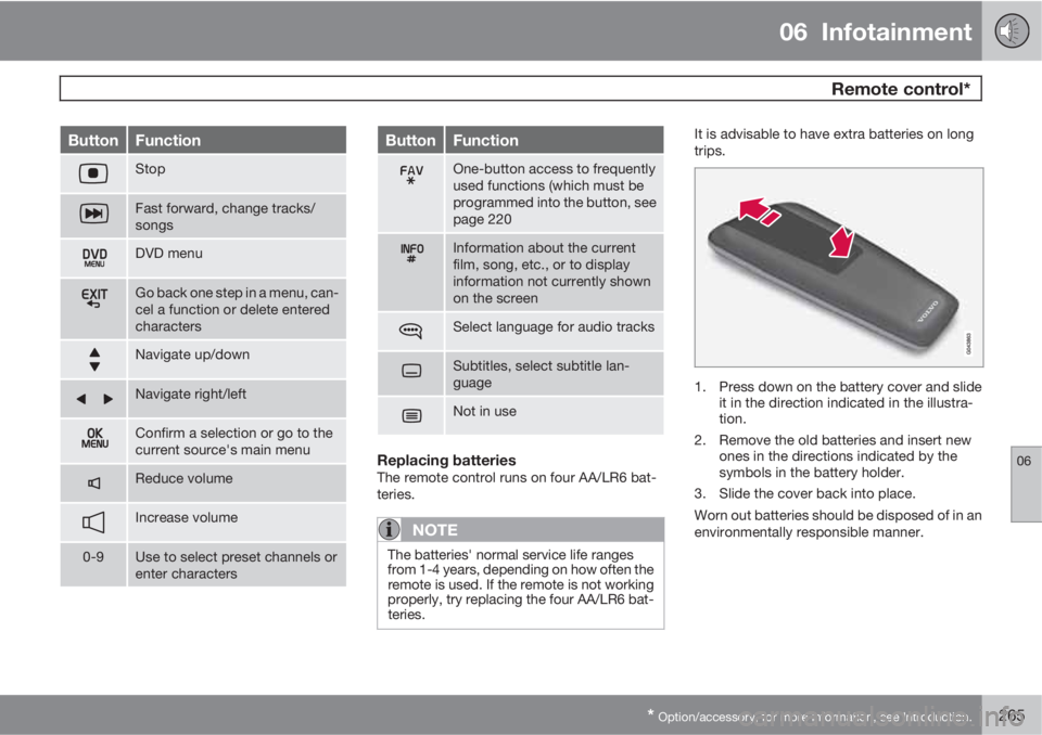
ButtonFunction
Stop
Fast forward, change tracks/
songs
DVD menu
Go back one step in a menu, can-
cel a function or delete entered
characters
Navigate up/down
Navigate right/left
Confirm a selection or go to the
current source's main menu
Reduce volume
Increase volume
0-9Use to select preset channels or
enter characters
ButtonFunction
One-button access to frequently
used functions (which must be
programmed into the button, see
page 220
Information about the current
film, song, etc., or to display
information not currently shown
on the screen
Select language for audio tracks
Subtitles, select subtitle lan-
guage
Not in use
Replacing batteriesThe remote control runs on four AA/LR6 bat-
teries.
NOTE
The batteries' normal service life ranges
from 1-4 years, depending on how often the
remote is used. If the remote is not working
properly, try replacing the four AA/LR6 bat-
teries.
It is advisable to have extra batteries on long
trips.
1. Press down on the battery cover and slide
it in the direction indicated in the illustra-
tion.
2. Remove the old batteries and insert new
ones in the directions indicated by the
symbols in the battery holder.
3. Slide the cover back into place.
Worn out batteries should be disposed of in an
environmentally responsible manner.
Page 271 of 382
07 During your trip
Driving recommendations
07
269
tributed so that capacity weight or maximum
permissible axle loads are not exceeded.
Driving through water
•The vehicle can be driven through water up
to a depth of approximately 10 in. (25 cm),
at a maximum speed of 6 mph (10 km/h).
•Take particular care when driving through
flowing water.
•Clean the electrical connections for trailer
wiring after driving in mud or water.
•When driving through water, maintain low
speed and do not stop in the water.
WARNING
After driving through water, press lightly on
the brake pedal to ensure that the brakes
are functioning normally. Water or mud can
make the brake linings slippery, resulting in
delayed braking effect.
CAUTION
•Engine damage will occur if water is
drawn into the air cleaner.
•If the vehicle is driven through water
deeper than 10 in (25 cm), water may
enter the differential and the transmis-
sion. This reduces the oil's lubricating
capacity and may shorten the service
life of these components.
•Do not allow the vehicle to stand in
water up to the door sills longer than
absolutely necessary. This could result
in electrical malfunctions.
•If the engine has been stopped while the
vehicle is in water, do not attempt to
restart it. Have the vehicle towed out of
the water.
Engine and cooling systemUnder special conditions, for example when
driving in hilly terrain, extreme heat or with
heavy loads, there is a risk that the engine and
cooling system will overheat. Proceed as fol-
lows to avoid overheating the engine.
•Maintain a low speed when driving with a
trailer up long, steep hills.
•Do not turn the engine off immediately
when stopping after a hard drive.
WARNING
The cooling fan may start or continue to
operate (for up to 6 minutes) after the engine
has been switched off.
•Remove any auxiliary lights from in front of
the grille when driving in hot weather con-
ditions.
•Do not exceed engine speeds of 4500 rpm
if driving with a trailer in hilly terrain. The oil
temperature could become too high.
Conserving electrical currentKeep the following in mind to help minimize
battery drain:
•When the engine is not running, avoid
using ignition mode II. Many electrical sys-
tems (the audio system, the optional navi-
gation system, power windows, etc) will
function in ignition modes 0 and I. These
modes reduce drain on the battery.
•Please keep in mind that using systems,
accessories, etc., that consume a great
deal of current when the engine is not run-
ning could result in the battery being com-
pletely drained. Driving or having the
engine running for approximately
15 minutes will help keep the battery
charged.
•The optional 12 volt socket in the cargo
area provides electrical current even with
Page 272 of 382

07 During your trip
Driving recommendations
07
270
the ignition switched off, which drains the
battery.
Before a long distance tripIt is always worthwhile to have your vehicle
checked by a trained and qualified Volvo serv-
ice technician before driving long distances.
Your retailer will also be able to supply you with
bulbs, fuses, spark plugs and wiper blades for
your use in the event that problems occur.
As a minimum, the following items should be
checked before any long trip:
•Check that engine runs smoothly and that
fuel consumption is normal.
•Check for fuel, oil, and fluid leakage.
•Have the transmission oil level checked.
•Check condition of drive belts.
•Check state of the battery's charge.
•Examine tires carefully (the spare tire as
well), and replace those that are worn.
Check tire pressures.
•The brakes, front wheel alignment, and
steering gear should be checked by a
trained and qualified Volvo service techni-
cian only.
•Check all lights, including high beams.
•Reflective warning triangles are legally
required in some states/provinces.
•Have a word with a trained and qualified
Volvo service technician if you intend to
drive in countries where it may be difficult
to obtain the correct fuel.
•Consider your destination. If you will be
driving through an area where snow or ice
are likely to occur, consider snow tires.
Cold weather precautionsIf you wish to check your vehicle before the
approach of cold weather, the following advice
is worth noting:
•Make sure that the engine coolant contains
50 percent antifreeze. Any other mixture
will reduce freeze protection. This gives
protection against freezing down to
–31 °F (–35 °C). The use of "recycled" anti-
freeze is not approved by Volvo. Different
types of antifreeze must not be mixed.
•Volvo recommends using only genuine
Volvo antifreeze in your vehicle's radiator.
•Try to keep the fuel tank well filled – this
helps prevent the formation of condensa-
tion in the tank. In addition, in extremely
cold weather conditions it is worthwhile to
add fuel line de-icer before refueling.
•The viscosity of the engine oil is important.
Oil with low viscosity (thinner oil) improves
cold-weather starting as well as decreas-
ing fuel consumption while the engine is
warming up. 0W-30 oil is recommended fordriving in areas with sustained low temper-
atures.
•The load placed on the battery is greater
during the winter since the windshield wip-
ers, lighting, etc., are used more often.
Moreover, the capacity of the battery
decreases as the temperature drops. In
very cold weather, a poorly charged bat-
tery can freeze and be damaged. It is there-
fore advisable to check the state of charge
more frequently and spray an anti-rust oil
on the battery posts.
•Volvo recommends the use of snow tires
on all four wheels for winter driving, see
page 306.
•To prevent the washer fluid reservoir from
freezing, add washer solvents containing
antifreeze. This is important since dirt is
often splashed on the windshield during
winter driving, requiring the frequent use of
the washers and wipers. Volvo Washer
Solvent should be diluted as follows: Down
to 14 °F (–10 °C): 1 part washer solvent and
4 parts water Down to 5 °F (–15 °C): 1 part
washer solvent and 3 parts water Down to
0 °F (–18 °C): 1 part washer solvent and
2 parts water Down to –18 °F (–28 °C):
1 part washer solvent and 1 part water.
•Use Volvo Teflon Lock Spray in the locks.
•Avoid using de-icing sprays as they can
cause damage to the locks.
Page 279 of 382
07 During your trip
Loading
07
277
CAUTION
Be sure that there is adequate space above
and behind the vehicle before opening the
tailgate automatically.
The vehicle should not be driven or moved
with the tailgate in the open position. How-
ever, if the vehicle is moved with the tailgate
in the open position, the automatic closing
function will be inoperative until one of the
following occurs:
•The tailgate is closed manually
•The ignition is switched off and the key
is removed for approximately 10
minutes (the tailgate will function again
after restart).
NOTE
If the tailgate has been opened and closed
continuously too long, the automatic func-
tion will be deactivated to avoid overloading
the electrical system. The automatic func-
tion can be used again after approximately
2 minutes.
If the vehicle's battery has been discharged
or disconnected, the tailgate must be
opened and closed once manually to reset
the system.
Programming the tailgate opening angleThe tailgate's maximum opening angle can be
programmed, which can be useful, for exam-
ple, if the tailgate has to be opened in a garage
with a low ceiling.
To do so:
•Open the tailgate manually, hold it at the
desired maximum opening angle and
press the tailgate's closing button for at
least 3 seconds. When the tailgate is
released, programming is complete.
•To remove this programming, open the tail-
gate manually to a higher opening angle.
Automatic closingThe power tailgate can be closed by pressing
the
button on the tailgate (see the illus-
tration) or by pressing it down.
NOTE
If the tailgate is pressed down e.g., by the
weight of snow or strong wind, it will close
automatically.
WARNING
Be sure that no one is near the tailgate when
it is opened or closed automatically. The
tailgate should never be obstructed in any
way when it is operated.
Interrupting automatic opening/closingAutomatic opening or closing the tailgate can
be interrupted in four ways:
•By pressing the button on the
lighting panel.
•By pressing the button on the
remote key.
•By pressing the button on the lower edge
of the tailgate.
•By pressing the rubber-covered button
under the outer handle on the tailgate.
If one of these actions is taken, the tailgate will
stop moving.
Pinch protectionIf the tailgate is obstructed while it is being
operated, the pinch protection function is acti-
vated.
•If the tailgate is being opened, the electri-
cal function will be switched off and the
tailgate will be released from the electrical
system.
•If the tailgate is being closed, it will stop
and move slightly in the opposite direction.
Operating the tailgate manuallyThe power tailgate can be disconnected from
the vehicle’s electrical system by quickly pull-
Page 291 of 382
07 During your trip
Emergency towing
07
289
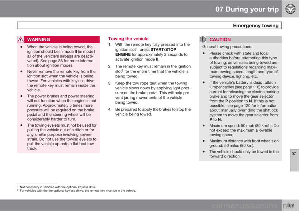
WARNING
•When the vehicle is being towed, the
ignition should be in mode II (in mode I,
all of the vehicle's airbags are deacti-
vated). See page 83 for more informa-
tion about ignition modes.
•Never remove the remote key from the
ignition slot when the vehicle is being
towed. For vehicles with keyless drive,
the remote key must remain inside the
vehicle.
•The power brakes and power steering
will not function when the engine is not
running. Approximately 5 times more
pressure will be required on the brake
pedal and the steering wheel will be
considerably harder to turn.
•The towing eyelets must not be used for
pulling the vehicle out of a ditch or for
any similar purpose involving severe
strain. Do not use the towing eyelets to
pull the vehicle up onto a flat bed tow
truck.
Towing the vehicle
1. With the remote key fully pressed into the
ignition slot1, press START/STOP
ENGINE for approximately 2 seconds to
activate ignition mode II.
2. The remote key must remain in the ignition
slot
2 for the entire time that the vehicle is
being towed.
3. Keep the tow rope taut when the towing
vehicle slows down by applying light pres-
sure on the brake pedal. This will help pre-
vent jarring movements of the vehicle
being towed.
4. Be prepared to apply the brakes to stop the
vehicle being towed.
CAUTION
General towing precautions:
•Please check with state and local
authorities before attempting this type
of towing, as vehicles being towed are
subject to regulations regarding maxi-
mum towing speed, length and type of
towing device, lighting, etc.
•If the vehicle's battery is dead, attach
jumper cables (see page 116) to provide
current for releasing the electric parking
brake and to move the gear selector
from the P position to N. If this is not
possible, see page 120 for information
about manually overriding the shiftlock
system to move the gear selector from
P to N.
•Maximum speed: 50 mph (80 km/h). Do
not exceed the maximum allowable
towing speed.
•Maximum distance with front wheels on
ground: 50 miles (80 km).
•The vehicle should only be towed in the
forward direction.
1Not necessary in vehicles with the optional keyless drive.2For vehicles with the the optional keyless dirive, the remote key must be in the vehicle.
Page 313 of 382
08 Wheels and tires
Tire Sealing System
08
311
7. Connect the electrical wire to the nearest
12-volt socket in the vehicle.
NOTE
Be sure that none of the other 12-volt sock-
ets is being used while the compressor is in
operation.
8. Start the vehicle’s engine.
WARNING
The vehicle´s engine should be running
when the tire sealing system is used to avoid
battery drain. Therefore, be sure the vehicle
is parked in a well ventilated place, or out-
doors, before using the system.
9. Start the tire sealing system’s compressor
by pressing the on/off switch to position I.
WARNING
•Never stand next to the tire being inflated
when the compressor is in operation.
•If cracks, bubbles, etc. form on the tire,
switch off the compressor immediately.
•If there is visible damage to the sidewall
or the rim, the tire cannot be repaired.
The vehicle should not be driven if this
occurs. Contact a towing service or
Volvo On Call Roadside Assistance if
applicable.
NOTE
The air pressure gauge will temporarily
show an increase in pressure to approxi-
mately 88 psi (6 bar) while the sealing com-
pound is being pumped into the tire. The
pressure should return to a normal level
after approximately 30 seconds.
10. Within seven minutes, inflate the tire to
between 22—44 psi (1.8—3.0 bar). Switch
off the compressor briefly to get a clear
reading from the pressure gauge.
CAUTION
The compressor should not be used for
more than 10 minutes at a time to avoid
overheating.
WARNING
If the pressure remains below 22 psi
(1.8 bar) after approximately seven minutes,
turn off the compressor. In this case, the
hole is too large to be sealed and the vehicle
should not be driven.
11. Switch off the compressor and disconnect
the electrical wire from the 12-volt socket.
12. Unscrew the hose from the tire’s inflation
valve and reinstall the valve cap.
13. Immediately drive the vehicle for approxi-
mately 2 miles (3 km) at a maximum speed
of 50 mph (80 km/h) to distribute the seal-
ing compound in the tire.
Page 315 of 382
08 Wheels and tires
Tire Sealing System
08
313 Inflating tires
The tire sealing system can be used to inflate
the tires. To do so:
1. Park the car in a safe place.
2. The compressor should be switched off.
Ensure that the on/off switch is in position
0 (the 0 side of the switch should be
pressed down).
3. Take out the electrical wire and hose.
4. Remove the valve cap from the tire’s infla-
tion valve and screw the hose connector
onto the valve as tightly as possible by
hand.
5. Connect the electrical wire to the nearest
12-volt socket in the vehicle.
6. Start the vehicle’s engine.WARNING
•The vehicle’s engine should be running
when the tire sealing system is used to
avoid battery drain. Therefore, be sure
the vehicle is parked in a well ventilated
place, or outdoors, before using the sys-
tem. The parking brake should be
securely applied and the gear selector
should be in the P (park) position.
•Children should never be left unattended
in the vehicle when the engine is running.
7. Check the tire’s inflation pressure on the
gauge. Switch off the compressor briefly to
get a clear reading from the pressure
gauge.
8. Refer to the tire inflation table in this chap-
ter for the correct inflation pressure. If the
tire needs to be inflated, start the tire seal-
ing system’s compressor (press the on/off
switch to position I). If necessary, release
air from the tire by turning the air release
knob counterclockwise.
CAUTION
The compressor should not be used for
more than 10 minutes at a time to avoid
overheating.
9. Turn off the compressor (press the on/off
switch to position 0) when the correct infla-
tion pressure has been reached.
10. Unscrew the hose from the tire’s inflation
valve and reinstall the valve cap.
11. Disconnect the electrical wire from the
12-volt socket.
Page 322 of 382
320
Volvo maintenance................................................................................ 322
Maintaining your car............................................................................. 323
Hood and engine compartment............................................................325
Engine oil............................................................................................... 326
Fluids..................................................................................................... 328
Replacing bulbs.................................................................................... 330
Wiper blades and washer fluid.............................................................. 337
Battery................................................................................................... 339
Fuses..................................................................................................... 342
Vehicle care........................................................................................... 350
Page 325 of 382

09 Maintenance and specifications
Maintaining your car09
323 Owner maintenance
Periodic maintenance requirements and inter-
vals are described in your vehicle's Warranty
and Service Records Information booklet.
The following points can be carried out
between the normally scheduled maintenance
services.
Each time the car is refueled:
•Check the engine oil level.
•Clean the windshield, windshield wipers,
headlights, and taillights.
Monthly:
•Check cold tire pressure in all tires. Inspect
the tires for wear.
•Check that engine coolant and other fluid
levels are between the indicated "min" and
"max" markings.
•Clean interior glass surfaces with a glass
cleaner and soft paper towels.
•Wipe driver information displays with a soft
cloth.
•Visually inspect battery terminals for cor-
rosion. Corrosion may indicate a loose ter-
minal connector, or a battery near the end
of its useful service life. Consult your Volvo
retailer for additional information.
As needed:Wash the car, including the undercarriage, to
reduce wear that can be caused by a buildup
of dirt, and corrosion that can be caused by salt
residues.
Clean leaves and twigs from air intake vents at
the base of the windshield, and from other pla-
ces where they may collect.
NOTE
Complete service information for qualified
technicians is available online for purchase
or subscription at www.volvotechinfo.com.
Hoisting the vehicle
If a garage jack is used to lift the vehicle, the
two jack attachments points should be used.They are specially reinforced to bear the weight
of the vehicle. A garage jack can also be placed
under the front of the engine support frame.
Take care not to damage the splash guard
under the engine. Ensure that the jack is posi-
tioned so that the vehicle cannot slide off it.
Always use axle stands or similar structures.
If a two-post hoist is used to lift the vehicle, the
front and rear lift arm pads should be centered
under the reinforced lift plates on the inboard
edge of the sill rail (see illustration).
Emission inspection readiness
What is an Onboard Diagnostic System
(OBD II)?
OBD II is part of your vehicle's computerized
engine management system. It stores diagnos-
tic information about your vehicle's emission
controls. It can light the Check Engine light
(MIL) if it detects an emission control "fault." A
"fault" is a component or system that is not
performing within an expected range. A fault
may be permanent or temporary. OBD II will
store a message about any fault.
How do states use OBD II for emission
inspections?
Many states connect a computer directly to a
vehicle's OBD II system. The inspector can
then read "faults." In some states, this type of