warning lights VOLVO XC70 2013 Owner´s Manual
[x] Cancel search | Manufacturer: VOLVO, Model Year: 2013, Model line: XC70, Model: VOLVO XC70 2013Pages: 382, PDF Size: 6.78 MB
Page 29 of 382
01 Safety
Occupant Weight Sensor01
27
WARNING
•Never try to open, remove, or repair any
components in the OWS system. This
could result in system malfunction.
Maintenance or repairs should only be
carried out by an a trained and qualified
Volvo service technician.
•The front passenger's seat should not
be modified in any way. This could
reduce pressure on the seat cushion,
which might interfere with the OWS sys-
tem's function.
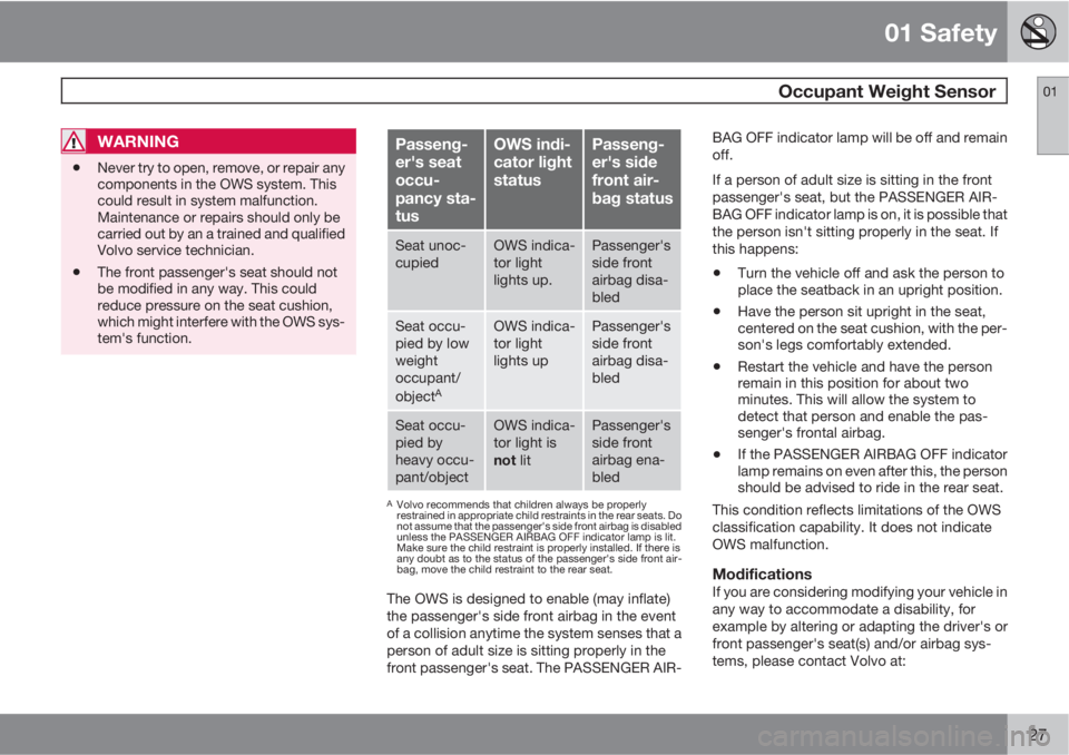
Passeng-
er's seat
occu-
pancy sta-
tusOWS indi-
cator light
statusPasseng-
er's side
front air-
bag status
Seat unoc-
cupiedOWS indica-
tor light
lights up.Passenger's
side front
airbag disa-
bled
Seat occu-
pied by low
weight
occupant/
object
A
OWS indica-
tor light
lights upPassenger's
side front
airbag disa-
bled
Seat occu-
pied by
heavy occu-
pant/objectOWS indica-
tor light is
not litPassenger's
side front
airbag ena-
bled
AVolvo recommends that children always be properly
restrained in appropriate child restraints in the rear seats. Do
not assume that the passenger's side front airbag is disabled
unless the PASSENGER AIRBAG OFF indicator lamp is lit.
Make sure the child restraint is properly installed. If there is
any doubt as to the status of the passenger's side front air-
bag, move the child restraint to the rear seat.
The OWS is designed to enable (may inflate)
the passenger's side front airbag in the event
of a collision anytime the system senses that a
person of adult size is sitting properly in the
front passenger's seat. The PASSENGER AIR-BAG OFF indicator lamp will be off and remain
off.
If a person of adult size is sitting in the front
passenger's seat, but the PASSENGER AIR-
BAG OFF indicator lamp is on, it is possible that
the person isn't sitting properly in the seat. If
this happens:
•Turn the vehicle off and ask the person to
place the seatback in an upright position.
•Have the person sit upright in the seat,
centered on the seat cushion, with the per-
son's legs comfortably extended.
•Restart the vehicle and have the person
remain in this position for about two
minutes. This will allow the system to
detect that person and enable the pas-
senger's frontal airbag.
•If the PASSENGER AIRBAG OFF indicator
lamp remains on even after this, the person
should be advised to ride in the rear seat.
This condition reflects limitations of the OWS
classification capability. It does not indicate
OWS malfunction.
ModificationsIf you are considering modifying your vehicle in
any way to accommodate a disability, for
example by altering or adapting the driver's or
front passenger's seat(s) and/or airbag sys-
tems, please contact Volvo at:
Page 80 of 382
03 Your driving environment
Instruments and controls
03
78
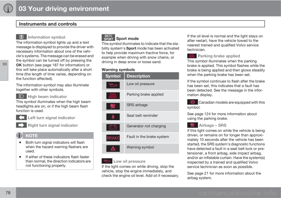
Information symbol
The information symbol lights up and a text
message is displayed to provide the driver with
necessary information about one of the vehi-
cle's systems. The message can be erased and
the symbol can be turned off by pressing the
OK button (see page 187 for information) or
this will take place automatically after a short
time (the length of time varies, depending on
the function affected).
The information symbol may also illuminate
together with other symbols.
High beam indicator
This symbol illuminates when the high beam
headlights are on, or if the high beam flash
function is used.
Left turn signal indicator
Right turn signal indicator
NOTE
•Both turn signal indicators will flash
when the hazard warning flashers are
used.
•If either of these indicators flash faster
than normal, the direction indicators are
not functioning properly.
Sport mode
This symbol illuminates to indicate that the sta-
bility system's Sport mode has been activated
to help provide maximum tractive force, for
example when driving with snow chains, or
driving in deep snow or loose sand.
Warning symbols
SymbolDescription
Low oil pressure
Parking brake applied
SRS airbags
Seat belt reminder
Generator not charging
Fault in the brake system
Warning symbol
Low oil pressure
If the light comes on while driving, stop the
vehicle, stop the engine immediately, and
check the engine oil level. Add oil if necessary.If the oil level is normal and the light stays on
after restart, have the vehicle towed to the
nearest trained and qualified Volvo service
technician.
Parking brake applied
This symbol illuminates when the parking
brake is applied. This symbol flashes while the
brake is being applied and then glows steadily
when the parking brake has been set.
If the symbol continues to flash after the brake
has been set, this indicates that a fault has
been detected. See the message in the infor-
mation display.
Canadian models are equipped with this
symbol.
See page 124 for more information about
using the parking brake.
Airbags – SRS
If this light comes on while the vehicle is being
driven, or remains on for longer than approxi-
mately 10 seconds after the vehicle has been
started, the SRS system's diagnostic functions
have detected a fault in a seat belt lock or pre-
tensioner, a front airbag, side impact airbag,
and/or an inflatable curtain. Have the system(s)
inspected by a trained and qualified Volvo
service technician as soon as possible.
See page 21 for more information about the
airbag system.
Page 81 of 382
03 Your driving environment
Instruments and controls
03
79
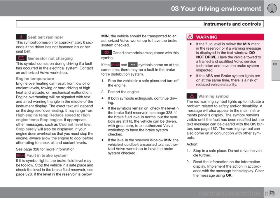
Seat belt reminder
This symbol comes on for approximately 6 sec-
onds if the driver has not fastened his or her
seat belt.
Generator not charging
This symbol comes on during driving if a fault
has occurred in the electrical system. Contact
an authorized Volvo workshop.
Engine temperatureEngine overheating can result from low oil or
coolant levels, towing or hard driving at high
heat and altitude, or mechanical malfunction.
Engine overheating will be signaled with text
and a red warning triangle in the middle of the
instrument display. The exact text will depend
on the degree of overheating. It may range from
High engine temp Reduce speed to High
engine temp Stop engine. If appropriate,
other messages, such as Coolant level low,
Stop safely will also be displayed. If your
engine does overheat so that you must stop the
engine, always allow the engine to cool before
attempting to check oil and coolant levels.
See page 328 for more information.
Fault in brake system
If this symbol lights, the brake fluid level may
be too low. Stop the vehicle in a safe place and
check the level in the brake fluid reservoir, see
page 328. If the level in the reservoir is belowMIN, the vehicle should be transported to an
authorized Volvo workshop to have the brake
system checked.
Canadian models are equipped with this
symbol.
If the
and symbols come on at the
same time, there may be a fault in the brake
force distribution system.
1. Stop the vehicle in a safe place and turn off
the engine.
2. Restart the engine.
•If both symbols extinguish, continue driv-
ing.
•If the symbols remain on, check the level in
the brake fluid reservoir, see page 328. If
the brake fluid level is normal but the sym-
bols are still lit, the vehicle can be driven,
with great care, to an authorized Volvo
workshop to have the brake system
checked.
•If the level in the reservoir is below MIN, the
vehicle should be transported to an author-
ized Volvo workshop to have the brake
system checked.
WARNING
•If the fluid level is below the MIN mark
in the reservoir or if a warning message
is displayed in the text window: DO
NOT DRIVE. Have the vehicle towed to
a trained and qualified Volvo service
technician and have the brake system
inspected.
•If the ABS and Brake system lights are
on at the same time, there is a risk of
reduced vehicle stability.
Warning symbol
The red warning symbol lights up to indicate a
problem related to safety and/or drivability. A
message will also appear in the main instru-
ments panel's display. The symbol remains
visible until the fault has been rectified but the
text message can be cleared with the OK but-
ton, see page 187. The warning symbol can
also come on in conjunction with other sym-
bols.
Action:
1. Stop in a safe place. Do not drive the vehi-
cle further.
2. Read the information on the information
display. Implement the action in accord-
ance with the message in the display. Clear
the message using OK.
Page 84 of 382
03 Your driving environment
Ignition modes
03
82* Option/accessory, for more information, see Introduction.
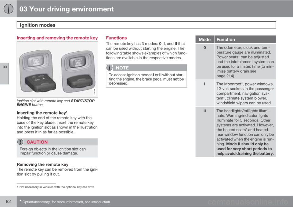
Inserting and removing the remote key
Ignition slot with remote key and START/STOP
ENGINE button.
Inserting the remote key1
Holding the end of the remote key with the
base of the key blade, insert the remote key
into the ignition slot as shown in the illustration
and press it in as far as possible.
CAUTION
Foreign objects in the ignition slot can
impair function or cause damage.
Removing the remote keyThe remote key can be removed from the igni-
tion slot by pulling it out.
Functions
The remote key has 3 modes: 0, I, and II that
can be used without starting the engine. The
following table shows examples of which func-
tions are available in the respective modes.
NOTE
To access ignition modes I or II without star-
ting the engine, the brake pedal must not be
depressed.
ModeFunction
0The odometer, clock and tem-
perature gauge are illuminated.
Power seats* can be adjusted
and the infotainment system can
be used for a limited time (to min-
imize battery drain see
page 214).
IThe Moonroof*, power windows,
12-volt sockets in the passenger
compartment, navigation sys-
tem*, climate system blower,
windshield wipers can be used.
IIThe headlights/taillights illumi-
nate. Warning/indicator lights
illuminate for 5 seconds. Other
systems are activated. However,
the heated seats* and heated
rear window function can only be
activated when the engine is run-
ning. Mode II should only be
used for very short periods to
help avoid draining the battery.
1Not necessary in vehicles with the optional keyless drive.
Page 99 of 382
03 Your driving environment
Lighting
03
97
NOTE
Regulations regarding the use of the front
fog lights may vary, depending on where
you drive.
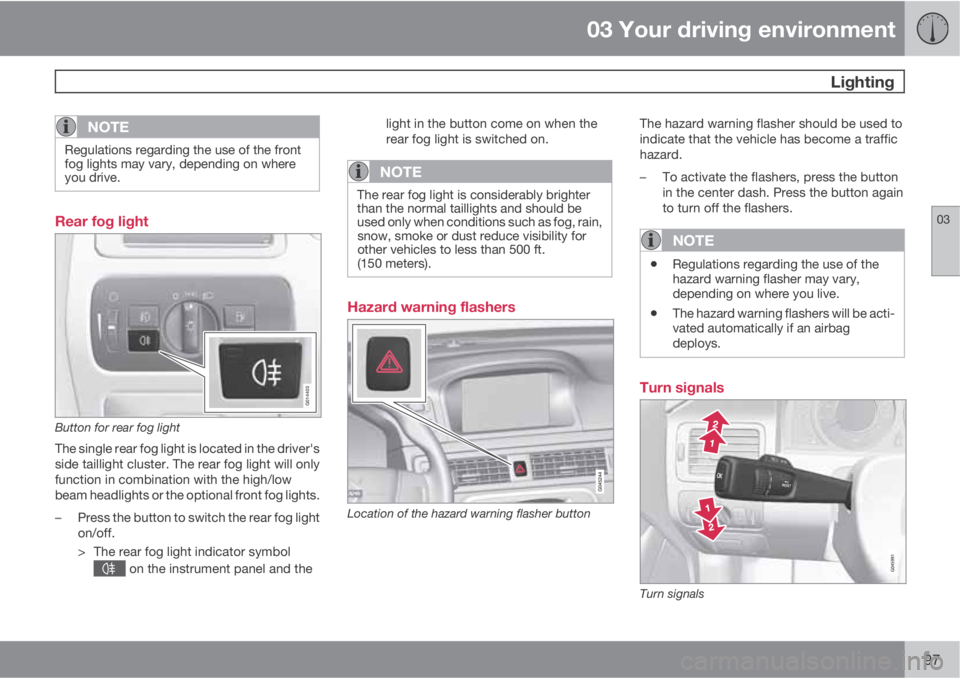
Rear fog light
G014403
Button for rear fog light
The single rear fog light is located in the driver's
side taillight cluster. The rear fog light will only
function in combination with the high/low
beam headlights or the optional front fog lights.
–Press the button to switch the rear fog light
on/off.
> The rear fog light indicator symbol
on the instrument panel and thelight in the button come on when the
rear fog light is switched on.
NOTE
The rear fog light is considerably brighter
than the normal taillights and should be
used only when conditions such as fog, rain,
snow, smoke or dust reduce visibility for
other vehicles to less than 500 ft.
(150 meters).
Hazard warning flashers
Location of the hazard warning flasher button
The hazard warning flasher should be used to
indicate that the vehicle has become a traffic
hazard.
–To activate the flashers, press the button
in the center dash. Press the button again
to turn off the flashers.
NOTE
•Regulations regarding the use of the
hazard warning flasher may vary,
depending on where you live.
•The hazard warning flashers will be acti-
vated automatically if an airbag
deploys.
Turn signals
Turn signals
Page 123 of 382
03 Your driving environment
Brakes
03
* Option/accessory, for more information, see Introduction.121 Brake system
The brake system is a hydraulic system con-
sisting of two separate brake circuits. If a prob-
lem should occur in one of these circuits, it is
still possible to stop the vehicle with the other
brake circuit.
If the brake pedal must be depressed farther
than normal and requires greater foot pressure,
the stopping distance will be longer.
A warning light in the instrument panel will light
up to warn the driver that a fault has occurred.
If this light comes on while driving or braking,
stop immediately and check the brake fluid
level in the reservoir.
NOTE
Press the brake pedal hard and maintain
pressure on the pedal – do not pump the
brakes.
WARNING
If the fluid level is below the MIN mark in the
reservoir or if a brake system message is
shown in the information display: DO NOT
DRIVE. Have the vehicle towed to a trained
and qualified Volvo service technician and
have the brake system inspected.
Brake pad inspectionOn vehicles equipped with a jack*, the condi-
tion of the brake pads can be checked by rais-
ing the vehicle (see page 314 for information
about using the jack and removing a wheel)
and performing a visual inspection of the brake
pads.
WARNING
•If the vehicle has been driven immedi-
ately prior to a brake pad inspection, the
wheel hub, brake components, etc., will
be very hot. Allow time for these com-
ponents to cool before carrying out the
inspection.
•Apply the parking brake and put the
gear selector in the Park (P) position.
•Block the wheels standing on the
ground, use rigid wooden blocks or
large stones.
WARNING
•Use the jack intended for the vehicle
when changing a tire. For any other job,
use stands to support the vehicle.
•The jack should be kept well-greased
and clean, and should not be damaged.
•Be sure the jack is on a firm, level, non-
slippery surface.
•No objects should be placed between
the base of jack and the ground, or
between the jack and the attachment
bar on the vehicle.
•The jack must correctly engage the jack
attachment.
•Never allow any part of your body to be
extended under a vehicle supported by
a jack.
Brake lightsThe brake lights come on automatically when
the brakes are applied.
Adaptive brake lightsThe adaptive brake lights activate in the event
of sudden braking or if the ABS system is acti-
vated. This function causes an additional tail-
light on each side of the vehicle to illuminate to
help alert vehicles traveling behind.
The adaptive brake lights activate if:
Page 129 of 382
03 Your driving environment
Hill Descent Control (HDC)*
03
* Option/accessory, for more information, see Introduction.127 Introduction
Normally, when the accelerator pedal is
released while driving down hills, the vehicle's
speed slows as the engine runs at lower rpm
(the normal engine braking effect). However, if
the downhill gradient becomes steeper and if
the vehicle is carrying a load, speed increases
despite the engine braking effect. In this situa-
tion, the brakes must be applied to reduce the
vehicle's speed.
HDC is a type of automatic engine brake and
makes it possible to increase or decrease the
vehicle's speed on downhill gradients using
only the accelerator pedal, without applying
the brakes. The brake system functions auto-
matically to maintain a low and steady speed.
HDC is particularly useful when driving down
steep hills with rough surfaces, and where the
road may have slippery patches.
WARNING
HDC does not function in all situations, and
is a supplementary braking aid. The driver
has full responsibility for driving in a safe
manner.
Function
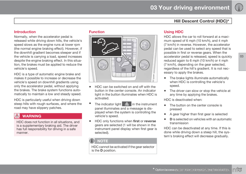
•HDC can be switched on and off with the
button in the center console. An indicator
light in the button illuminates when HDC is
activated.
•The indicator light in the instrument
panel illuminates and a message is dis-
played when the system is controlling the
vehicle's speed.
•HDC only functions when first or reverse
gears are selected (1 will be shown in the
instrument panel display when first gear is
selected).
NOTE
HDC cannot be activated if the gear selector
is the D position.
Using HDC
HDC allows the car to roll forward at a maxi-
mum speed of 6 mph (10 km/h), and 4 mph
(7 km/h) in reverse. However, the accelerator
pedal can be used to select any speed that is
possible in first or reverse gears. When the
accelerator pedal is released, speed is quickly
reduced again to 6 mph (10 km/h) or 4 mph
(7 km/h), depending on the gear selected,
regardless of the hill's gradient. It is not nec-
essary to apply the brakes.
•The brake lights illuminate automatically
when HDC is controlling the vehicle's
speed.
•The driver can slow or stop the vehicle at
any time by applying the brakes.
HDC is deactivated when:
•The button on the center console is
pressed
•A gear higher than first gear is selected
•D is selected on vehicles with an automatic
transmission
HDC can be deactivated at any time. If this is
done while driving down a steep hill, the sys-
tem's braking effect will decrease gradually.
Page 146 of 382
04 Driver support
Adaptive Cruise Control (ACC)*
04
144* Option/accessory, for more information, see Introduction.
•Your vehicle's speed goes below 10 mph
(15 km/h) and ACC cannot determine if the
target object is a stationary vehicle or some
other type of object such as e.g., a speed
bump.
•Your vehicle's speed goes below 10 mph
(15 km/h) and the vehicle ahead turns so
that ACC no longer has a target vehicle to
follow.
No automatic braking when at a
standstill
In certain situations, ACC will no longer apply
the brakes and go into standby mode while the
vehicle is not moving. This means that the
driver will have to apply the brakes.
This happens if:
•The driver presses the brake pedal
•The parking brake is activated
•The gear selected is moved to P,N or R
•The driver presses the button to put
ACC in standby mode
The parking brake is applied
automatically
In certain situations, ACC will apply the parking
brake in order to continue keeping the vehicle
at a standstill.
This happens if:
•The driver opens the door or takes off
his/her seat belt
•DSTC is put in Sport mode (see page 132)
•ACC has kept the vehicle at a standstill for
more than 2 minutes
•The engine has been switched off
•The brakes have overheated
Turning ACC off completely
•From standby mode, press once.
•From active mode, press twice.
The set speed and time interval are then
cleared from the system's memory and cannot
be resumed by pressing
.
The radar sensor and its limitations
In addition to being used by ACC, the radar
sensor is also used by Distance Alert (see
page 149) and Collision Warning with Full
Auto-brake and Pedestrian Detection (see
page 158). This sensor is designed to detect
cars or larger vehicles driving in the same
direction as your vehicle, in the same lane.
WARNING
Accessories or other objects, such as extra
headlights, must not be installed in front of
the grille.
Modification of the radar sensor could make
its use illegal.
The radar sensor's capacity to detect vehicles
ahead is impeded:
•if the radar sensor is obstructed and can-
not detect other vehicles, for example in
heavy rain, or if snow or other objects are
obscuring the radar sensor.
NOTE
Keep the area in front of the radar sensor
clean.
•if the speed of vehicles ahead is signifi-
cantly different from your own speed.
Page 155 of 382
04 Driver support
City Safety™
04
153 Function
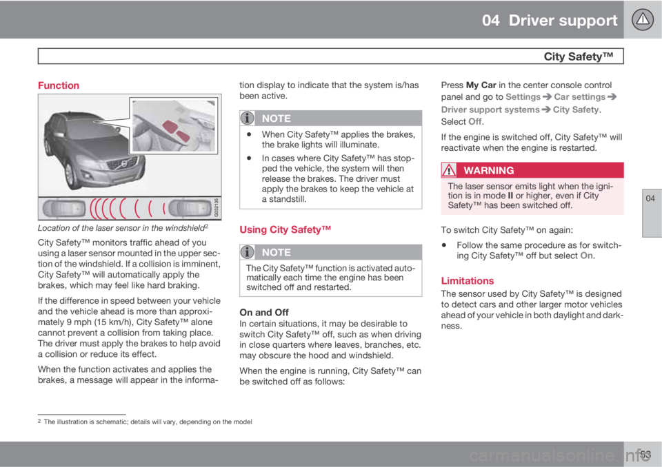
Location of the laser sensor in the windshield2
City Safety™ monitors traffic ahead of you
using a laser sensor mounted in the upper sec-
tion of the windshield. If a collision is imminent,
City Safety™ will automatically apply the
brakes, which may feel like hard braking.
If the difference in speed between your vehicle
and the vehicle ahead is more than approxi-
mately 9 mph (15 km/h), City Safety™ alone
cannot prevent a collision from taking place.
The driver must apply the brakes to help avoid
a collision or reduce its effect.
When the function activates and applies the
brakes, a message will appear in the informa-tion display to indicate that the system is/has
been active.
NOTE
•When City Safety™ applies the brakes,
the brake lights will illuminate.
•In cases where City Safety™ has stop-
ped the vehicle, the system will then
release the brakes. The driver must
apply the brakes to keep the vehicle at
a standstill.
Using City Safety™
NOTE
The City Safety™ function is activated auto-
matically each time the engine has been
switched off and restarted.
On and OffIn certain situations, it may be desirable to
switch City Safety™ off, such as when driving
in close quarters where leaves, branches, etc.
may obscure the hood and windshield.
When the engine is running, City Safety™ can
be switched off as follows:Press My Car in the center console control
panel and go to Settings
Car settings
Driver support systemsCity Safety.
Select
Off.
If the engine is switched off, City Safety™ will
reactivate when the engine is restarted.
WARNING
The laser sensor emits light when the igni-
tion is in mode II or higher, even if City
Safety™ has been switched off.
To switch City Safety™ on again:
•Follow the same procedure as for switch-
ing City Safety™ off but select On.
Limitations
The sensor used by City Safety™ is designed
to detect cars and other larger motor vehicles
ahead of your vehicle in both daylight and dark-
ness.
2The illustration is schematic; details will vary, depending on the model
Page 156 of 382
04 Driver support
City Safety™
04
154
WARNING
The laser sensor has certain limitations and
its function may be reduced (or it may not
function at all) in conditions such as heavy
rain or snowfall, or by dense fog or thick,
blowing dust or snow. Condensation, dirt,
ice or snow on the windshield may also
interfere with the sensor’s function.
Objects such as warning flags hanging from
long objects on the roof or accessories such as
auxiliary lights or protective arches on the front
of the vehicle that are higher than the hood may
also impede the sensor’s function.
Braking distance to the vehicle ahead increa-
ses on slippery road surfaces, which may
reduce City Safety’s capacity to avoid a colli-
sion. In situations like this, the DSTC system
(see page 132) will help provide the best pos-
sible braking capacity and stability.
City Safety™ emits a laser beam and measures
the way in which the light is reflected. There-
fore, vehicles or objects with low-reflective sur-
faces may not be detected. Normally, the
license plate and taillight reflectors give the
rear section of a vehicle ahead sufficient reflec-
tive surfaces to be detected.
NOTE
•Keep the windshield in front of the laser
sensor free of ice, snow, dirt, etc. See
page 153.
•Snow or ice on the hood deeper than
2 inches (5 cm) may obstruct the sen-
sor. Keep the hood free of ice and snow.
•Do not mount or in any way attach any-
thing on the windshield that could
obstruct the laser sensor.
Troubleshooting
If Windscreen Sensors blocked appears in
the information display, this indicates that the
City Safety™ laser sensor is obstructed in
some way and cannot detect vehicles ahead of
you, which means that the system is not func-
tioning.
However, this message will not be displayed in
all situations in which the sensor is obstructed.
For this reason, the driver must ensure that the
area of the windshield in front of the sensor is
always kept clean.
The following table shows some of the situa-
tions that can cause the message to be dis-
played and suggested actions.
CauseAction
The area of the
windshield in front of
the sensor is dirty or
covered by ice or
snow.Clean the wind-
shield or remove the
ice/snow.
The laser sensor's
field of view is
obstructed.Remove the
obstruction.