belt VOLVO XC70 2015 Owner´s Manual
[x] Cancel search | Manufacturer: VOLVO, Model Year: 2015, Model line: XC70, Model: VOLVO XC70 2015Pages: 408, PDF Size: 11.26 MB
Page 147 of 408
03 Your driving environment
Parking brake
03
}}
145
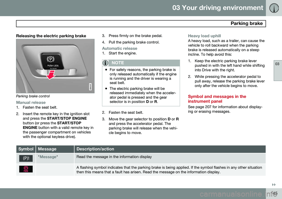
Releasing the electric parking brake
Parking brake control
Manual release1. Fasten the seat belt.
2. Insert the remote key in the ignition slotand press the START/STOP ENGINE
button (or press the START/STOP
ENGINE button with a valid remote key in
the passenger compartment on vehicles with the optional keyless drive). 3. Press firmly on the brake pedal.
4. Pull the parking brake control.
Automatic release1. Start the engine.
NOTE
•
For safety reasons, the parking brake is only released automatically if the engineis running and the driver is wearing aseat belt.
• The electric parking brake will bereleased immediately when the acceler-ator pedal is pressed and the gearselector is in position
D or R.
2. Fasten the seat belt.
3. Move the gear selector to position D or R
and press the accelerator pedal. The parking brake will release when the vehi-cle begins to move.
Heavy load uphillA heavy load, such as a trailer, can cause the vehicle to roll backward when the parkingbrake is released automatically on a steepincline. To help avoid this:
1. Keep the electric parking brake lever pushed in with the left hand while shifting into Drive with the right.
2. While pressing the accelerator pedal to pull away, release the parking brake leveronly after the vehicle begins to move.
Symbol and messages in the instrument panel
See page 207 for information about display- ing or erasing messages.
SymbolMessageDescription/action
"Message"Read the message in the information display
A flashing symbol indicates that the parking brake is being applied. If the symbol flashes in any other situation then this means that a fault has arisen. Read the message on the information display.
Page 162 of 408
04 Driver support
Adaptive Cruise Control (ACC)*
04
160* Option/accessory, for more information, see Introduction.
WARNING
Adaptive Cruise Control only warns of vehicles detected by the radar sensor, seepage 165. In some cases there may be nowarning or the warning may be delayed.The driver should always apply the brakeswhen necessary.
Steep inclines and/or heavy loadsACC is primarily intended for use on fairly level roads. The system may have difficultymaintaining the correct distance to a vehicleahead on steep inclines, if the vehicle is car-rying a heavy load or is towing a trailer. Inthese situations, the driver should always beprepared to apply the brakes if necessary.
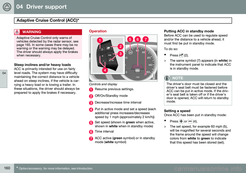
Operation
Controls and display
Resume previous settings.
Off/On/Standby mode
Decrease/increase time interval
Put in active mode and set a speed (each additional press increases/decreasesspeed by 1 mph (approximately 2 km/h))
Set speed (shown in green when active,
shown in white when in standby mode)
Time interval
ACC active ( green symbol) or in standby
mode ( white symbol)
Putting ACC in standby modeBefore ACC can be used to regulate speed and/or the distance to a vehicle ahead, itmust first be put in standby mode. To do so:
• Press
(2).
> The same symbol (7) appears (in white) in
the instrument panel to indicate that ACC is in standby mode.
NOTE
The driver's door must be closed and the driver's seat belt must be fastened beforeACC can be put in active mode. If the driv-er's seat belt is taken off or if the driver'sdoor is opened, ACC will return to standbymode.
Setting a speedOnce ACC has been put in standby mode: • Press
or (4).
> The set speed, for example 60 mph (5), will be magnified for several seconds and the frame around the speed will changecolors from white to green to indicate
that this speed has been stored (set).
Page 164 of 408
04 Driver support
Adaptive Cruise Control (ACC)*
04
162* Option/accessory, for more information, see Introduction.
Standby mode (temporary deactivation)To temporarily deactivate ACC (put it in standby mode):
• Press
.
This symbol and the marking for the set speed with change colors from green to
white. The previously set speed and time interval are resumed by pressing
.
WARNING
The vehicle may accelerate quickly after
has been pressed if its current speed is
considerably lower than the set speed.
Standby mode due to action by the driver
ACC is temporarily deactivated and put in standby mode:
• if the brakes are applied
• if the gear selector is moved to
N
• if the driver drives faster than the set speed for more than
1 minute.
In this happens, the driver will have to regu- late the vehicle's speed.
NOTE
If the accelerator pedal is only depressed for a short time, such as when passinganother vehicle, ACC is deactivated tem-porarily and is reactivated when the pedalis released.
Automatic standby modeACC is linked to other systems such as the stability and traction control system (DSTC). Ifthis system is not functioning properly, ACCwill switch off automatically. In the event of automatic deactivation, an audible signal will sound and the message
Cruise control Cancelled is shown in the
instrument panel. The driver must then inter- vene and adapt the vehicle's speed to thesurrounding traffic and regulate the distanceto the vehicle ahead. An automatic switch to standby mode may be caused if:
• engine speed (rpm) is too high/low
• The driver's door is opened
• The driver unbuckles his/her seat belt
• the vehicle's speed goes below 18 mph (30 km/h)
• the wheels lose traction
• brake temperature is high •
the radar sensor is obstructed by, forexample, wet snow or rain.
Resuming the set speedIf ACC is in standby mode, it can be reactiva- ted by pressing the
button on the steering
wheel keypad. The vehicle will return to the most recently set speed.
WARNING
The vehicle may accelerate quickly after
has been pressed if its current speed is
considerably lower than the set speed.
Passing another vehicleIf your vehicle’s speed is being regulated by ACC and the driver indicates that he/shewould like to pass the vehicle ahead by usingthe left turn signal, ACC can assist by accel-
erating briefly. This function is active at speeds above approximately 45 mph (70 km/h).
Page 165 of 408
04 Driver support
Adaptive Cruise Control (ACC)*
04
}}
* Option/accessory, for more information, see Introduction.163
WARNING
Please be aware that this function will also cause the vehicle to accelerate briefly incertain situations other than passinganother vehicle, for example using the leftturn signal to indicate a lane change or aturn toward a highway exit at speedsabove approximately 45 mph (70 km/h).
Turning ACC off completely
•
From standby mode, press once.
• From active mode, press
twice.
The set speed and time interval are then cleared from the system's memory and can- not be resumed by pressing
.
Toggling between ACC and CC (standard Cruise Control)
Switching from ACC to CCThis may be useful if, for example, the radar sensor is obstructed in some way. See thesection "The radar sensor and its limitations"on page 165 for additional information.
• Press and hold the
button; the symbol
in the instrument panel will switch from
to .
> This activates the standard cruise control function (see page 156).
WARNING
Switching from ACC to CC means that:
• Your vehicle will
no longer automati-
cally maintain a set distance to a vehi- cle ahead.
• Only the set speed will be maintainedand the driver will have to apply thebrakes when needed.
Switching from CC to ACC
Switch off cruise control by pressing once
or twice as needed according to the instruc- tions in the previous section "Turning ACC offcompletely." The next time the system isswitched on, ACC will be reactivated.
Queue Assist
IntroductionQueue Assist is an added ACC feature that is linked to your vehicle's automatic transmis-sion. Queue Assist consists of the following func- tions: • Enhanced speed interval (including when the vehicle is at a complete stop or is moving at speed below 18 mph(30 km/h))
• Automatic standby mode when ACCchanges target vehicles
• No automatic braking when at a standstill
• The parking brake is applied automati-cally
Please note that the lowest speed that can be set is 18 mph (30 km/h), although ACC canmaintain a set speed/distance to a vehicleahead down to a standstill. Queue Assistconsists of the following features:
Enhanced speed interval
NOTE
The driver's door must be closed and the driver's seat belt must be fastened beforeACC can be put in active mode. If the driv-er's seat belt is taken off or if the driver'sdoor is opened, ACC will return to standbymode.
Your vehicle can maintain the set time interval to the vehicle ahead at any permissiblespeed, including a complete stop. In order to activate ACC at speeds below 18 mph (30 km/h):
Page 167 of 408
04 Driver support
Adaptive Cruise Control (ACC)*
04
}}
* Option/accessory, for more information, see Introduction.165
•
The gear selected is moved to
P,N or R
• The driver presses the
button to put
ACC in standby mode
The parking brake is applied
automatically
In certain situations, ACC will apply the park- ing brake in order to continue keeping thevehicle at a standstill. This happens if:
• The driver opens the door or takes off his/her seat belt
• DSTC is put in Sport mode (seepage 152)
• ACC has kept the vehicle at a standstillfor more than 2 minutes
• The engine has been switched off
• The brakes have overheated
The radar sensor and its limitations
In addition to being used by ACC, the radar sensor is also used by Distance Alert (seepage 169) and Collision Warning with FullAuto-brake and Pedestrian Detection (seepage 178). This sensor is designed to detectcars or larger vehicles driving in the samedirection as your vehicle, in the same lane.
WARNING
• If there is visible damage to the front grille or you suspect that the radarsensor may be damaged in any way,contact a trained and qualified Volvoservice technician as soon as possible.The radar sensor may only functionpartially (or not at all) if it is damagedor is not securely fastened in place.
• Accessories or other objects, such asextra headlights, must not be installedin front of the grille.
• Modification of the radar sensor couldmake its use illegal.
The radar sensor's capacity to detect vehi- cles ahead is impeded:
• if the radar sensor is obstructed and can- not detect other vehicles, for example inheavy rain, or if snow or other objects areobscuring the radar sensor.
NOTE
Keep the area in front of the radar sensor clean.
• if the speed of vehicles ahead is signifi- cantly different from your own speed.
Situations where ACC may not function optimally
WARNING
•The radar sensor has a limited field of vision. In some situations it may detecta vehicle later than expected or notdetect other vehicles at all.
• If ACC is not functioning properly,cruise control will also be disabled.
Page 288 of 408
07 During your trip
Driving recommendations
07
286
WARNING
The cooling fan may start or continue to operate (for up to 6 minutes) after theengine has been switched off.
•Remove any auxiliary lights from in front of the grille when driving in hot weatherconditions.
• Do not exceed engine speeds of4500 rpm if driving with a trailer in hillyterrain. The oil temperature could becometoo high.
Conserving electrical currentKeep the following in mind to help minimize battery drain:
• When the engine is not running, avoid using ignition mode
II. Many electrical
systems (the audio system, the optionalnavigation system, power windows, etc)will function in ignition modes 0 and I.
These modes reduce drain on the battery.
• Please keep in mind that using systems,accessories, etc., that consume a greatdeal of current when the engine is notrunning could result in the battery beingcompletely drained. Driving or having theengine running for approximately15 minutes will help keep the batterycharged. •
The optional 12-volt socket in the cargoarea provides electrical current even withthe ignition switched off, which drains thebattery.
Before a long distance tripIt is always worthwhile to have your vehicle checked by a trained and qualified Volvoservice technician before driving long dis-tances. Your retailer will also be able to sup-ply you with bulbs, fuses, spark plugs andwiper blades for your use in the event thatproblems occur. As a minimum, the following items should be checked before any long trip:
• Check that engine runs smoothly and that fuel consumption is normal.
• Check for fuel, oil, and fluid leakage.
• Have the transmission oil level checked.
• Check condition of drive belts.
• Check state of the battery's charge.
• Examine tires carefully (the spare tire aswell), and replace those that are worn.Check tire pressures.
• The brakes, front wheel alignment, andsteering gear should be checked by atrained and qualified Volvo service techni-cian only.
• Check all lights, including high beams. •
Reflective warning triangles are legallyrequired in some states/provinces.
• Have a word with a trained and qualifiedVolvo service technician if you intend todrive in countries where it may be difficultto obtain the correct fuel.
• Consider your destination. If you will bedriving through an area where snow or iceare likely to occur, consider snow tires.
Cold weather precautionsIf you wish to check your vehicle before the approach of cold weather, the followingadvice is worth noting:
• Make sure that the engine coolant con- tains 50 percent antifreeze. Any othermixture will reduce freeze protection. Thisgives protection against freezing down to–31 °F (–35 °C). The use of "recycled"antifreeze is not approved by Volvo. Dif-ferent types of antifreeze must not bemixed.
• Volvo recommends using only genuineVolvo antifreeze in your vehicle's radiator.
• Try to keep the fuel tank well filled – thishelps prevent the formation of condensa-tion in the tank. In addition, in extremelycold weather conditions it is worthwhileto add fuel line de-icer before refueling.
• The viscosity of the engine oil is impor-tant. Oil with low viscosity (thinner oil)
Page 297 of 408
07 During your trip
Loading
07
}}
295
tailgate will be released from the electrical system.
• If the tailgate is being
closed, it will stop
and move slightly in the opposite direc-tion.
Operating the tailgate manuallyThe power tailgate can be disconnected from the vehicle’s electrical system by quickly pull-ing the outer handle twice. The tailgate canthen be opened/closed manually.
Folding down the rear seat backrests
The rear seat backrests can be folded down for additional loading space, see page 95.
Load anchoring eyelets
The load anchoring eyelets on both sides of the vehicle are used to fasten straps, etc., tohelp anchor items in the cargo area.
WARNING
• Cover sharp edges on long loads to help prevent injury to occupants.Secure the load to help prevent shift-ing during sudden stops.
• Always secure large and heavy objectswith a seat belt or cargo retainingstraps.
• Always secure the load to help preventit from moving in the event of suddenstops.
• Switch off the engine, apply the park-ing brake and put the gear selector inP
when loading and unloading the
vehicle.
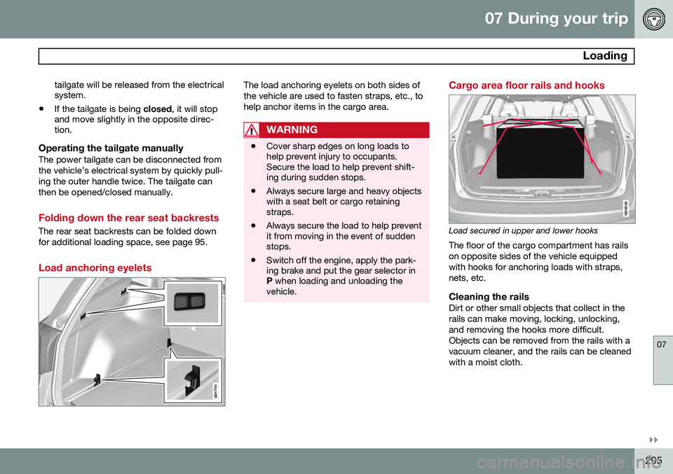
Cargo area floor rails and hooks
Load secured in upper and lower hooks The floor of the cargo compartment has rails on opposite sides of the vehicle equippedwith hooks for anchoring loads with straps,nets, etc.
Cleaning the railsDirt or other small objects that collect in therails can make moving, locking, unlocking,and removing the hooks more difficult.Objects can be removed from the rails with avacuum cleaner, and the rails can be cleanedwith a moist cloth.
Page 342 of 408
09 Maintenance and specifications
Volvo maintenance 09
340
Introduction
Periodic maintenance will help keep your vehicle running well. The maintenance serv-ices contain several checks that require spe-cial instruments and tools and therefore mustbe performed by a qualified technician. Tokeep your Volvo in top condition, specifytime-tested and proven Genuine Volvo Partsand Accessories.
The Federal Clean Air Act – U.S.The Federal Clean Air Act requires vehiclemanufacturers to furnish written instructionsto the ultimate purchaser to assure the properservicing and function of the components thatcontrol emissions. These services, which arelisted in the "Warranty and Service RecordsInformation" booklet, are not covered by thewarranty. You will be required to pay for laborand material used.
MaintenanceYour Volvo passed several major inspectionsbefore it was delivered to you, in accordancewith Volvo specifications. The maintenanceprocedures outlined in the Warranty andService Records Information booklet, many ofwhich will positively affect your vehicle'semissions, should be performed as indicated.It is recommended that receipts for vehicleemission maintenance be retained in casequestions arise concerning maintenance.Inspection and maintenance should also beperformed anytime a malfunction is observedor suspected.
Applicable warranties – U.S./CanadaIn accordance with applicable U.S. andCanadian regulations, the following list ofwarranties is provided.
• New Vehicle Limited Warranty
• Parts and Accessories Limited Warranty
• Corrosion Protection Limited Warranty
• Seat Belt and Supplemental Restraint Systems Limited Warranty
• Emission Design and Defect Warranty
• Emission Performance Warranty
These are the federal warranties; other war- ranties are provided as required by state/provincial law. Refer to your separate War-ranty and Service Records Information book-let for detailed information concerning eachof the warranties.
Periodic maintenance helps minimize emissions
NOTE
• Refer to your Warranty and Service Records Information booklet for acomprehensive service and mainte-nance schedule up to 150,000 miles(240,000 km). This program containsinspections and services necessary forthe proper function of your vehicle andincludes components that affect vehi-cle emissions.
• The Warranty and Service RecordsInformation booklet also containsdetailed information concerning thewarranties that apply to your vehicle.
Page 379 of 408
09 Maintenance and specifications
Vehicle care09
}}
377
If there are stains on the steering wheel: Type 1
(ink, wine, coffee, milk, sweat or
blood)
–Use a soft cloth or sponge. Wipe the wheel with a solution with 5% ammonia.For blood stains, mix approx. 1 cup (2 dl)of water and one ounce (25g) of salt andwipe the stain.
Type 2 (fat, oil, sauces, or chocolate)
1. Same procedure as for type I stains.
2. Finish by rubbing the wheel with absorb- ent paper or a towel.
Type 3 (dry soil or dust)
1. Remove the soil/dust with a soft brush.
2. Same procedure as for type I stains.
CAUTION
Sharp objects, such as rings, could dam- age the leather on the steering wheel.
Cleaning the seat beltsClean only with lukewarm water and a mild soap solution.
Cleaning floor matsThe floor mats should be vacuumed orbrushed clean regularly, especially duringwinter when they should be taken out for dry- ing. Spots on textile mats can be removedwith a mild detergent. For best protection inwinter, Volvo recommends the use of Volvorubber floor mats. Consult your Volvo retailer.
Spots on interior plastic, metal, or wood surfaces
Cleaning interior plastic components should be done with a cleaning agent speciallydesigned for this purpose. Consult your Volvoretailer.
Touching up paintwork
Paint damage requires immediate attention to avoid rusting. Make it a habit to check the fin-ish regularly, for instance washing the vehicle.Touch-up if necessary. Paint repairs require special equipment and skill. Contact your Volvo retailer for anyextensive damage. Minor scratches can be repaired by using Volvo touch-up paint.
Color code
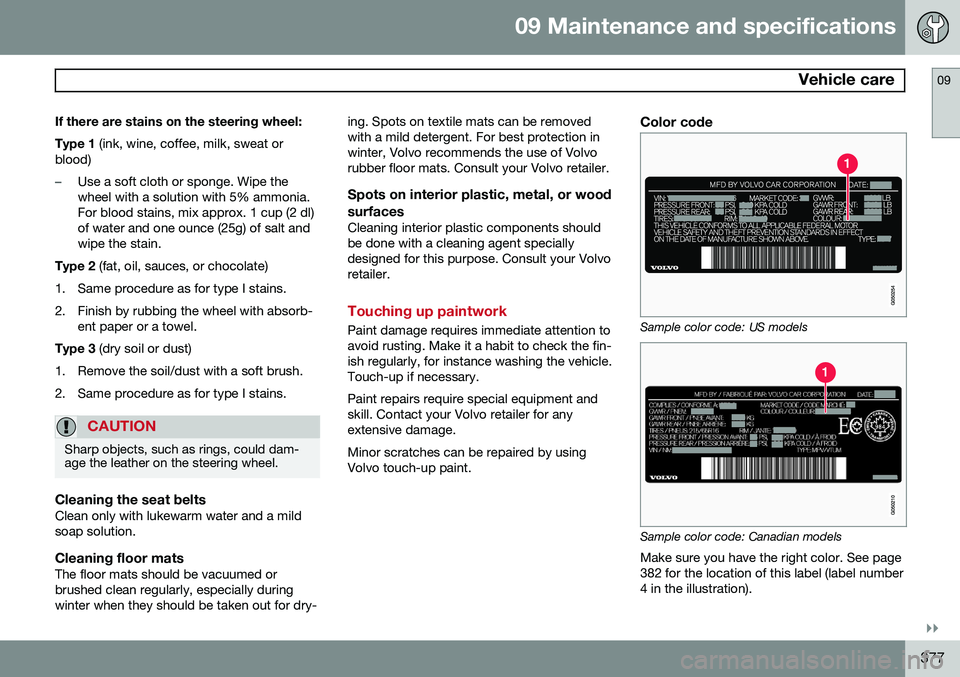
Sample color code: US models
Sample color code: Canadian models
Make sure you have the right color. See page 382 for the location of this label (label number4 in the illustration).
Page 393 of 408
10 Specifications
Overview of information and warning symbols
10
}}
* Option/accessory, for more information, see Introduction.391
Introduction
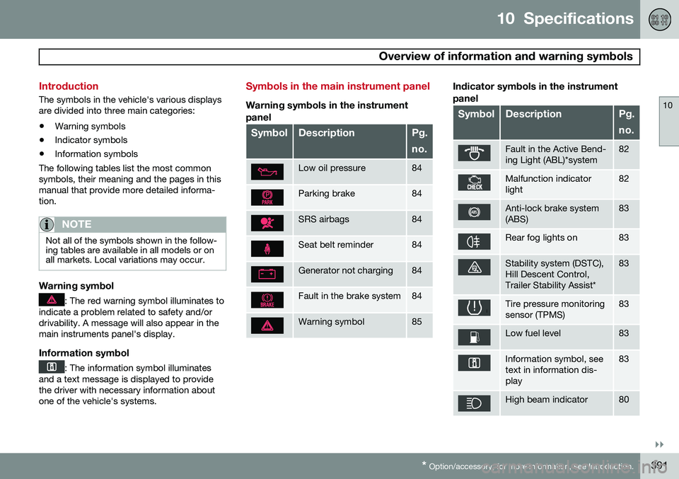
The symbols in the vehicle's various displays are divided into three main categories:
• Warning symbols
• Indicator symbols
• Information symbols
The following tables list the most commonsymbols, their meaning and the pages in thismanual that provide more detailed informa-tion.
NOTE
Not all of the symbols shown in the follow- ing tables are available in all models or onall markets. Local variations may occur.
Warning symbol
: The red warning symbol illuminates to
indicate a problem related to safety and/or drivability. A message will also appear in themain instruments panel's display.
Information symbol
: The information symbol illuminates
and a text message is displayed to provide the driver with necessary information aboutone of the vehicle's systems.
Symbols in the main instrument panel
Warning symbols in the instrument
panel
SymbolDescriptionPg. no.
Low oil pressure84
Parking brake84
SRS airbags84
Seat belt reminder84
Generator not charging84
Fault in the brake system84
Warning symbol85
Indicator symbols in the instrument panel
SymbolDescriptionPg. no.
Fault in the Active Bend- ing Light (ABL)*system82
Malfunction indicator light82
Anti-lock brake system (ABS)83
Rear fog lights on83
Stability system (DSTC), Hill Descent Control,Trailer Stability Assist*83
Tire pressure monitoring sensor (TPMS)83
Low fuel level83
Information symbol, see text in information dis-play83
High beam indicator80