power steering VOLVO XC70 2015 Owner´s Manual
[x] Cancel search | Manufacturer: VOLVO, Model Year: 2015, Model line: XC70, Model: VOLVO XC70 2015Pages: 408, PDF Size: 11.26 MB
Page 5 of 408
Contents
* Option/accessory, for more information, see Introduction.3
03
03 Your driving environment
Instruments and controls.......................... 78
Ignition modes.......................................... 88
Seats......................................................... 90
Steering wheel.......................................... 97
Lighting..................................................... 99
Wipers and washers............................... 107
Windows................................................. 110
Mirrors..................................................... 112
Digial compass*...................................... 115
Power moonroof* ................................... 117 HomeLink ®
Wireless Control System*.... 119
Starting the engine.................................. 122
Transmission........................................... 127
Eco Guide* and Power Meter*................ 132
Eco* ........................................................ 134
Start/Stop* ............................................. 137
Brakes..................................................... 141
Parking brake.......................................... 144
Hill Descent Control (HDC)*.................... 147
04
04 Driver support
Stability system....................................... 152
Road sign information (RSI)* .................. 154
Cruise control.......................................... 156
Adaptive Cruise Control (ACC)*.............. 158
Distance Alert* ....................................... 169
City Safety™ .......................................... 172Pedestrian and Cyclist Detection with
Full Auto Brake*...................................... 178
Driver Alert System* ............................... 188
Park assist*............................................. 193
Rear Park Assist Camera (PAC)* ............ 197
Blind Spot Information System (BLIS)*... 200
05
05 Comfort and driving pleasure
Volvo Sensus.......................................... 206
Menus and messages............................. 207
The MY CAR menus............................... 209
Climate system....................................... 215
Trip computer......................................... 225
Active chassis system–Four C*............... 232
Passenger compartment convenience... 233
Page 78 of 408
76* Option/accessory, for more information, see Introduction. Instruments and controls........................................................................ 78 Ignition modes........................................................................................ 88Seats....................................................................................................... 90Steering wheel........................................................................................ 97Lighting................................................................................................... 99
Wipers and washers.............................................................................. 107Windows............................................................................................... 110Mirrors................................................................................................... 112
Digial compass*.................................................................................... 115
Power moonroof* ................................................................................. 117 HomeLink
®
Wireless Control System*.................................................. 119
Starting the engine................................................................................ 122 Transmission......................................................................................... 127
Eco Guide* and Power Meter*.............................................................. 132Eco* ...................................................................................................... 134Start/Stop* ........................................................................................... 137Brakes................................................................................................... 141Parking brake........................................................................................ 144
Hill Descent Control (HDC)*.................................................................. 147
Page 81 of 408
03 Your driving environment
Instruments and controls
03
}}
* Option/accessory, for more information, see Introduction.79
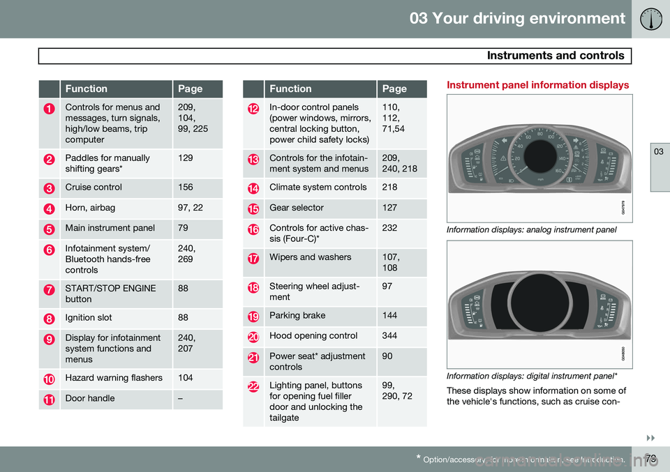
FunctionPage
Controls for menus and messages, turn signals,high/low beams, tripcomputer209, 104,99, 225
Paddles for manually shifting gears*129
Cruise control156
Horn, airbag97, 22
Main instrument panel79
Infotainment system/ Bluetooth hands-freecontrols240, 269
START/STOP ENGINE button88
Ignition slot88
Display for infotainment system functions andmenus240, 207
Hazard warning flashers104
Door handle–
FunctionPage
In-door control panels (power windows, mirrors,central locking button,power child safety locks)110, 112,71,54
Controls for the infotain- ment system and menus209, 240, 218
Climate system controls218
Gear selector127
Controls for active chas- sis (Four-C)*232
Wipers and washers107, 108
Steering wheel adjust- ment97
Parking brake144
Hood opening control344
Power seat* adjustment controls90
Lighting panel, buttons for opening fuel fillerdoor and unlocking thetailgate99, 290, 72
Instrument panel information displays
Information displays: analog instrument panel
Information displays: digital instrument panel* These displays show information on some of the vehicle's functions, such as cruise con-
Page 99 of 408
03 Your driving environment
Steering wheel
03
}}
* Option/accessory, for more information, see Introduction.97
Adjusting
G021138
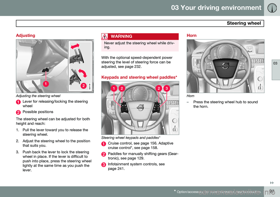
Adjusting the steering wheel
Lever for releasing/locking the steering wheel
Possible positions
The steering wheel can be adjusted for both height and reach:
1. Pull the lever toward you to release the steering wheel.
2. Adjust the steering wheel to the position that suits you.
3. Push back the lever to lock the steering wheel in place. If the lever is difficult to push into place, press the steering wheellightly at the same time as you push thelever.
WARNING
Never adjust the steering wheel while driv- ing.
With the optional speed-dependent power steering the level of steering force can beadjusted, see page 232.
Keypads and steering wheel paddles*
Steering wheel keypads and paddles*
Cruise control, see page 156. Adaptive cruise control*, see page 158.
Paddles for manually shifting gears (Gear- tronic), see page 129.
Infotainment system controls, see page 241.
Horn
Horn
–Press the steering wheel hub to sound the horn.
Page 132 of 408
03 Your driving environment
Transmission
03
130
Geartronic: starting on slippery
surfaces
Selecting 3rd gear in Geartronic’s manual shifting mode can help provide better tractionwhen starting off on slippery surfaces. To doso:
1. Depress the brake pedal and move the gear selector to the side from D toward
+S– .
2. Press the gear selector forward and release it (this selects 2nd gear). Press the selector forward again and release itto select 3rd gear. The optional steeringwheel paddles can also be used; see theprevious section "Geartronic: steeringwheel paddles."
3. Release the brake pedal and press gently on the accelerator pedal.
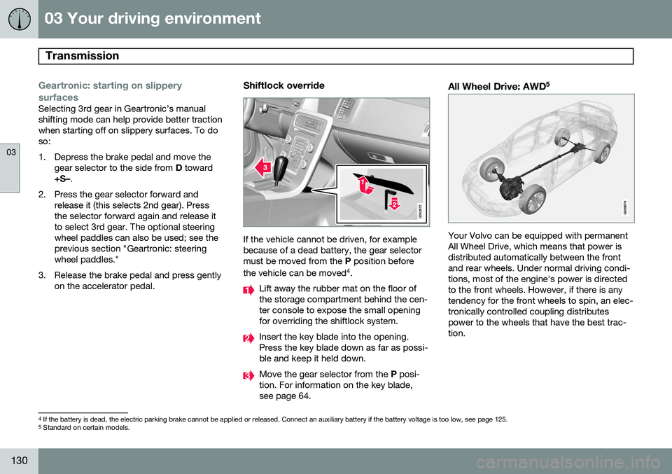
Shiftlock override
If the vehicle cannot be driven, for example because of a dead battery, the gear selectormust be moved from the P position before
the vehicle can be moved 4
.
Lift away the rubber mat on the floor of the storage compartment behind the cen-ter console to expose the small openingfor overriding the shiftlock system.
Insert the key blade into the opening. Press the key blade down as far as possi-ble and keep it held down.
Move the gear selector from the P posi-
tion. For information on the key blade, see page 64.
All Wheel Drive: AWD 5
Your Volvo can be equipped with permanent All Wheel Drive, which means that power isdistributed automatically between the frontand rear wheels. Under normal driving condi-tions, most of the engine's power is directedto the front wheels. However, if there is anytendency for the front wheels to spin, an elec-tronically controlled coupling distributespower to the wheels that have the best trac-tion.
4
If the battery is dead, the electric parking brake cannot be applied or released. Connect an auxiliary battery if the battery voltage is too low, see page 125.5
Standard on certain models.
Page 154 of 408
04 Driver support
Stability system
04
152
Introduction
The Dynamic Stability and Traction Control system (DSTC) consists of a number of func-tions designed to help reduce wheel spin,counteract skidding, and to generally helpimprove directional stability.
CAUTION
A pulsating sound will be audible when the system is actively operating and is normal.
Traction control (TC)This function is designed to help reduce wheel spin by transferring power from a drivewheel that begins to lose traction to thewheel on the opposite side of the vehicle (onthe same axle). TC is most active at low speeds.This is one of DSTC's permanent functions and cannot be switched off.
Active Yaw Control (AYC)This function helps maintain directional stabil-ity, for example when cornering, by brakingone or more of the wheels if the vehicleshows a tendency to skid or slide laterally.This is one of DSTC's permanent functionsand cannot be switched off.
Spin control (SC)The spin control function is designed to helpprevent the drive wheels from spinning whilethe vehicle is accelerating.
Trailer Stability Assist – TSA
1Trailer Stability Assist helps stabilize a vehiclethat is towing a trailer when the vehicle andtrailer have begun to sway. See page 304 formore information. This system is automatically deactivated if the driver selects
Sport mode.
Operation
Sport modeThe stability system is always activated and cannot be switched off. However, the driver can select Sport mode,
which offers more active driving characteris- tics. In this mode, the engine managementsystem monitors movement of the acceleratorpedal and steering wheel for sportier driving by allowing more lateral movement of the rearwheels before DSTC is activated. Under certain circumstances, such as when driving with snow chains, or driving in deepsnow or loose sand, it may be advisable totemporarily use
Sport mode for maximum
tractive force. If the driver releases pressure on the acceler- ator pedal, DSTC will also activate to helpstabilize the vehicle. To switch to Sport mode:
1. Press the My Car button in the center
console control panel and select
My
XC70
DSTC in the menu.
2. Unselect the symbol and leave the menu by pressing EXIT.
> This puts DSTC in Sport mode.
Sport mode remains active until the driver
switches it off in the menu or until the engine is switched off. DSTC will return to normalmode when the engine is restarted.
1 Included when a Volvo trailer hitch is installed
Page 234 of 408
05 Comfort and driving pleasure
Active chassis system–Four C*
05
232* Option/accessory, for more information, see Introduction.
Active chassis (Four C)
Active chassis, Four-C (Continuously Con- trolled Chassis Concept), regulates the cha-racteristics of the shock absorbers so that thevehicle's driving characteristics can beadjusted. There are three settings: Comfort,Sport and Advanced.
NOTE
This system is available on Canadian mod- els only.
ComfortComfort mode offers a somewhat softer ride and the transmission shifts gears at lowerrpm. This mode is particularly suitable forlong-distance highway driving. The indicatorlight in the button will be on when this modeis selected.
SportIn this mode, the vehicle's body sway isreduced during cornering and steeringresponse is more immediate. The transmis-sion shifts up at higher rpm for sportier driv-ing. The indicator light in the button will be onto indicate that Sport mode has beenselected.
AdvancedIn this mode, body sway in curves is minimaland steering response is very direct. Gearshifting is done at high rpm in each gear fordynamic and active driving.
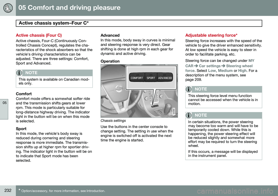
Operation
Chassis settings
Use the buttons in the center console to change setting. The setting in use when theengine is switched off is activated the nexttime the engine is started.
Adjustable steering force*
Steering force increases with the speed of the vehicle to give the driver enhanced sensitivity.At low speed the vehicle is easy to steer inorder to facilitate parking, etc. Steering force can be changed under
MY
CAR
Car settingsSteering wheel
force
. Select Low, Medium or High. For a
description of the menu system, see page 209.
NOTE
This steering force level menu function cannot be accessed when the vehicle is inmotion.
NOTE
In certain situations, the power steering may become too warm and will have to betemporarily cooled down. While this ishappening, the power steering effect willbe reduced slightly and somewhat moreeffort may be required to turn the steeringwheel. If this occurs, a message will be displayed in the instrument panel.
Page 288 of 408
07 During your trip
Driving recommendations
07
286
WARNING
The cooling fan may start or continue to operate (for up to 6 minutes) after theengine has been switched off.
•Remove any auxiliary lights from in front of the grille when driving in hot weatherconditions.
• Do not exceed engine speeds of4500 rpm if driving with a trailer in hillyterrain. The oil temperature could becometoo high.
Conserving electrical currentKeep the following in mind to help minimize battery drain:
• When the engine is not running, avoid using ignition mode
II. Many electrical
systems (the audio system, the optionalnavigation system, power windows, etc)will function in ignition modes 0 and I.
These modes reduce drain on the battery.
• Please keep in mind that using systems,accessories, etc., that consume a greatdeal of current when the engine is notrunning could result in the battery beingcompletely drained. Driving or having theengine running for approximately15 minutes will help keep the batterycharged. •
The optional 12-volt socket in the cargoarea provides electrical current even withthe ignition switched off, which drains thebattery.
Before a long distance tripIt is always worthwhile to have your vehicle checked by a trained and qualified Volvoservice technician before driving long dis-tances. Your retailer will also be able to sup-ply you with bulbs, fuses, spark plugs andwiper blades for your use in the event thatproblems occur. As a minimum, the following items should be checked before any long trip:
• Check that engine runs smoothly and that fuel consumption is normal.
• Check for fuel, oil, and fluid leakage.
• Have the transmission oil level checked.
• Check condition of drive belts.
• Check state of the battery's charge.
• Examine tires carefully (the spare tire aswell), and replace those that are worn.Check tire pressures.
• The brakes, front wheel alignment, andsteering gear should be checked by atrained and qualified Volvo service techni-cian only.
• Check all lights, including high beams. •
Reflective warning triangles are legallyrequired in some states/provinces.
• Have a word with a trained and qualifiedVolvo service technician if you intend todrive in countries where it may be difficultto obtain the correct fuel.
• Consider your destination. If you will bedriving through an area where snow or iceare likely to occur, consider snow tires.
Cold weather precautionsIf you wish to check your vehicle before the approach of cold weather, the followingadvice is worth noting:
• Make sure that the engine coolant con- tains 50 percent antifreeze. Any othermixture will reduce freeze protection. Thisgives protection against freezing down to–31 °F (–35 °C). The use of "recycled"antifreeze is not approved by Volvo. Dif-ferent types of antifreeze must not bemixed.
• Volvo recommends using only genuineVolvo antifreeze in your vehicle's radiator.
• Try to keep the fuel tank well filled – thishelps prevent the formation of condensa-tion in the tank. In addition, in extremelycold weather conditions it is worthwhileto add fuel line de-icer before refueling.
• The viscosity of the engine oil is impor-tant. Oil with low viscosity (thinner oil)
Page 307 of 408
07 During your trip
Towing a trailer
07
305
FunctionA vehicle towing a trailer may begin to sway for various reasons. Normally this only occursat high speeds but, for example, if the traileris overloaded or if the load is unevenly dis-tributed in the trailer, there is risk of swayingat speeds between approximately 45-55 mph(70-90 km/h). Swaying may be caused by factors such as: •The vehicle and trailer are hit by a sud- den, strong crosswind
• The vehicle and trailer are traveling on anuneven road surface or drive over a bump
• Sudden movements of the steering wheel
Facts about TSA
•
TSA intervenes at speeds above approxi-mately 40 mph (60 km/h)
• The DSTC symbol (
) in the instru-
ment panel will flash when TSA is working
• If the driver switches off the DSTC sys- tem's Spin Control function, TSA will alsobe switched off (but will be on again thenext time the engine is started)
• TSA may not intervene when the vehicleand trailer begin to sway if the driver triesto compensate for the swaying motion bymoving the steering wheel rapidly
How TSA worksOnce swaying has begun, it can be very diffi- cult to stop, which makes it difficult to controlthe vehicle and trailer. The TSA system continuously monitors the vehicle's movements, particularly lateralmovement. If the system detects a tendencyto sway, the brakes are applied individuallyon the front wheels, which has a stabilizingeffect on the vehicle and trailer. This is oftenenough to enable the driver to regain controlof the vehicle. If this is not adequate to stop the swaying motion, the brakes are applied to all of thewheels on the vehicle and on the trailer if it isequipped with brakes, and engine power istemporarily reduced. As the swaying motionbegins to decrease and the vehicle-trailerhave once again become stable, TSA will nowstop regulating the brakes/engine power andthe driver regains control of the vehicle.
Page 308 of 408
07 During your trip
Emergency towing
07
306
Towing eyelet
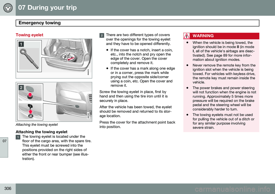
Attaching the towing eyelet
Attaching the towing eyeletThe towing eyelet is located under the floor of the cargo area, with the spare tire.This eyelet must be screwed into thepositions provided on the right sides ofeither the front or rear bumper (see illus-tration).
There are two different types of covers over the openings for the towing eyeletand they have to be opened differently.
• If the cover has a notch, insert a coin, etc., into the notch and pry open theedge of the cover. Open the covercompletely and remove it.
• If the cover has a mark along one edgeor in a corner, press the mark whileprying out the opposite side/cornerusing a coin, etc. Open the cover andremove it.
Screw the towing eyelet in place, first by hand and then using the tire iron until it issecurely in place. After the vehicle has been towed, the eyelet should be removed and returned to its stor-age location. Press the cover for the attachment point back into position.WARNING
• When the vehicle is being towed, the ignition should be in mode
II (in mode
I , all of the vehicle's airbags are deac-
tivated). See page 89 for more infor-mation about ignition modes.
• Never remove the remote key from theignition slot when the vehicle is beingtowed. For vehicles with keyless drive,the remote key must remain inside thevehicle.
• The power brakes and power steeringwill not function when the engine is notrunning. Approximately 5 times morepressure will be required on the brakepedal and the steering wheel will beconsiderably harder to turn.
• The towing eyelets must not be usedfor pulling the vehicle out of a ditch orfor any similar purpose involvingsevere strain.