sensor VOLVO XC70 2016 Owner´s Manual
[x] Cancel search | Manufacturer: VOLVO, Model Year: 2016, Model line: XC70, Model: VOLVO XC70 2016Pages: 396, PDF Size: 10.01 MB
Page 37 of 396
02 Safety
02
35
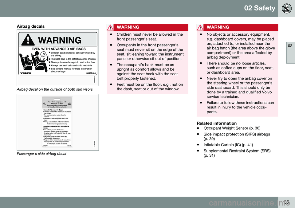
Airbag decals
Airbag decal on the outside of both sun visors
Passenger's side airbag decal
WARNING
•Children must never be allowed in the front passenger's seat.
• Occupants in the front passenger'sseat must never sit on the edge of theseat, sit leaning toward the instrumentpanel or otherwise sit out of position.
• The occupant's back must be asupright as comfort allows and beagainst the seat back with the seatbelt properly fastened.
• Feet must be on the floor, e.g., not onthe dash, seat or out of the window.
WARNING
•
No objects or accessory equipment, e.g. dashboard covers, may be placedon, attached to, or installed near theair bag hatch (the area above the glovecompartment) or the area affected byairbag deployment.
• There should be no loose articles,such as coffee cups on the floor, seat,or dashboard area.
• Never try to open the airbag cover onthe steering wheel or the passenger'sside dashboard. This should only bedone by a trained and qualified Volvoservice technician.
• Failure to follow these instructions canresult in injury to the vehicle occu-pants.
Related information
•
Occupant Weight Sensor (p. 36)
• Side impact protection (SIPS) airbags (p. 39)
• Inflatable Curtain (IC) (p. 41)
• Supplemental Restraint System (SRS)(p. 31)
Page 38 of 396
02 Safety
02
36
Occupant Weight Sensor
The Occupant Weight Sensor (OWS) is designed to meet the regulatory requirementsof Federal Motor Vehicle Safety Standard(FMVSS) 208 and is designed to disable (willnot inflate) the passenger's side front airbagunder certain conditions.
2
2
G017724
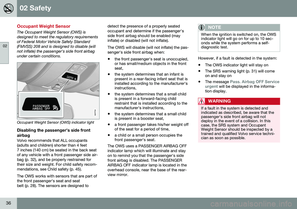
Occupant Weight Sensor (OWS) indicator light
Disabling the passenger's side frontairbag
Volvo recommends that ALL occupants (adults and children) shorter than 4 feet7 inches (140 cm) be seated in the back seatof any vehicle with a front passenger side air-bag (p. 32), and be properly restrained fortheir size and weight. For child safety recom-mendations, see Child safety (p. 45). The OWS works with sensors that are part of the front passenger's seat and seatbelt (p. 28). The sensors are designed to detect the presence of a properly seatedoccupant and determine if the passenger'sside front airbag should be enabled (mayinflate) or disabled (will not inflate). The OWS will disable (will not inflate) the pas- senger's side front airbag when:
• the front passenger's seat is unoccupied, or has small/medium objects in the frontseat,
• the system determines that an infant ispresent in a rear-facing infant seat that isinstalled according to the manufacturer'sinstructions,
• the system determines that a small childis present in a forward-facing childrestraint that is installed according to themanufacturer's instructions,
• the system determines that a small childis present in a booster seat,
• a front passenger takes his/her weight offof the seat for a period of time,
• a child or a small person occupies thefront passenger's seat.
The OWS uses a PASSENGER AIRBAG OFF indicator lamp which will illuminate and stayon to remind you that the passenger's sidefront airbag is disabled. The PASSENGERAIRBAG OFF indicator lamp is located in theoverhead console, near the base of the rear-view mirror.
NOTE
When the ignition is switched on, the OWS indicator light will go on for up to 10 sec-onds while the system performs a self-diagnostic test.
However, if a fault is detected in the system:
• The OWS indicator light will stay on
• The SRS warning light (p. 31) will come on and stay on
• The message
Pass. Airbag OFF Service
urgent will be displayed in the informa-
tion display.
WARNING
If a fault in the system is detected and indicated as described, be aware that thepassenger's side front airbag will notdeploy in the event of a collision. In thiscase, the SRS system and OccupantWeight Sensor should be inspected by atrained and qualified Volvo service techni-cian as soon as possible.
Page 40 of 396
||
02 Safety
02
38
1 Volvo Drive P.O. Box 914Rockleigh, New Jersey 076471-800-458-1552 In Canada Volvo Cars of Canada Corp. National Customer Service9130 Leslie Street, Suite 101Richmond Hill, Ontario L4B 0B91-800-663-8255WARNING
•No objects that add to the total weight on the seat should be placed on thefront passenger's seat. If a child isseated in the front passenger's seatwith any additional weight, this extraweight could cause the OWS systemto enable the airbag, which mightcause it to deploy in the event of a col-lision, thereby injuring the child.
• The seat belt should never be wrappedaround an object on the front pas-senger's seat. This could interfere withthe OWS system's function.
• The front passenger's seat belt shouldnever be used in a way that exertsmore pressure on the passenger thannormal. This could increase the pres-sure exerted on the weight sensor by achild, and could result in the airbagbeing enabled, which might cause it todeploy in the event of a collision,thereby injuring the child.
WARNING
• Keep the following points in mind with respect to the OWS system. Failure tofollow these instructions couldadversely affect the system's functionand result in serious injury to the occu-pant of the front passenger's seat:
• The full weight of the front seat pas-senger should always be on the seatcushion. The passenger should neverlift him/herself off the seat cushionusing the armrest in the door or thecenter console, by pressing the feet onthe floor, by sitting on the edge of theseat cushion, or by pressing againstthe backrest in a way that reducespressure on the seat cushion. Thiscould cause OWS to disable the front,passenger's side airbag.
Page 42 of 396
||
02 Safety
02
40
Components in the SIPS airbag systemThis SIPS airbag system consists of a gas generator, the side airbag modules built intothe outboard sides of both front seat back-rests, and electronic sensors/wiring.WARNING
•The SIPS airbag system is a supple- ment to the structural Side ImpactProtection System and the three-pointseat belt system. It is not designed todeploy during collisions from the frontor rear of the vehicle or in rollover sit-uations.
• The use of seat covers on the frontseats may impede SIPS airbag deploy-ment.
• No objects, accessory equipment orstickers may be placed on, attached toor installed near the SIPS airbag sys-tem or in the area affected by SIPS air-bag deployment.
• Never try to open or repair any compo-nents of the SIPS airbag system. Thisshould be done only by a trained andqualified Volvo service technician.
• In order for the SIPS airbag to provideits best protection, both front seatoccupants should sit in an uprightposition with the seat belt properly fas-tened.
• Failure to follow these instructions canresult in injury to the occupants of thevehicle in the event of an accident.
Related information
•
Supplemental Restraint System (SRS) (p. 31)
• Front airbags (p. 32)
• Inflatable Curtain (IC) (p. 41)
Page 49 of 396
02 Safety
02
}}
47
Volvo has some very specific recommendations:
•Always wear your seat belt (p. 28).
• Airbags are a SUPPLEMENTAL safety device which, when used with a three-point seat belt can help reduce seriousinjuries during certain types of accidents.Volvo recommends that you do not dis-connect the airbag system in your vehi-cle.
• Volvo strongly recommends that every-one in the vehicle be properly restrained.
• Volvo recommends that ALL occupants(adults and children) shorter than 4 feet7 inches (140 cm) be seated in the backseat of any vehicle with a front passengerside airbag.
• Drive safely!
Related information
• Infant seats (p. 49)
• Convertible seats (p. 51)
• Booster cushions (p. 53)
• Integrated booster cushion – generalinformation (p. 57)
• Child safety locks (p. 61)
• Top tether anchors (p. 56)
Child restraints
Suitable child restraints should always be used when children travel in the vehicle.
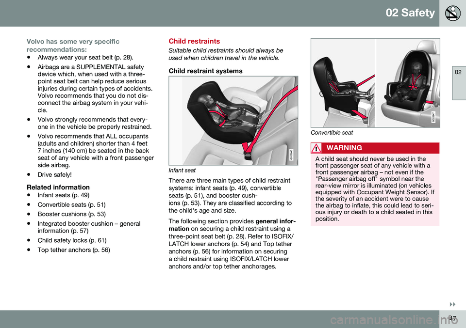
Child restraint systems
G022840
Infant seat
There are three main types of child restraint systems: infant seats (p. 49), convertibleseats (p. 51), and booster cush-ions (p. 53). They are classified according tothe child's age and size. The following section provides general infor-
mation on securing a child restraint using a
three-point seat belt (p. 28). Refer to ISOFIX/ LATCH lower anchors (p. 54) and Top tetheranchors (p. 56) for information on securinga child restraint using ISOFIX/LATCH loweranchors and/or top tether anchorages.
G022847
Convertible seat
WARNING
A child seat should never be used in the front passenger seat of any vehicle with afront passenger airbag – not even if the"Passenger airbag off" symbol near therear-view mirror is illuminated (on vehiclesequipped with Occupant Weight Sensor). Ifthe severity of an accident were to causethe airbag to inflate, this could lead to seri-ous injury or death to a child seated in thisposition.
Page 52 of 396
||
02 Safety
02
50
WARNING
A child seat should never be used in the front passenger seat of any vehicle with afront passenger airbag – not even if the"Passenger airbag off" symbol near therear-view mirror is illuminated (on vehiclesequipped with Occupant Weight Sensor). Ifthe severity of an accident were to causethe airbag to inflate, this could lead to seri-ous injury or death to a child seated in thisposition.
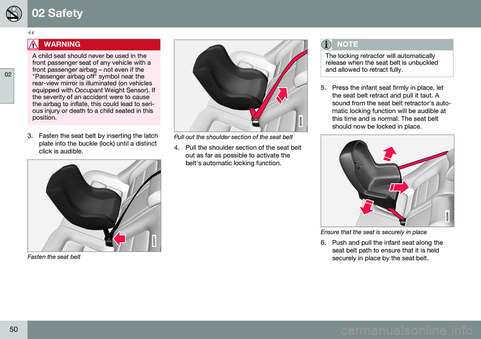
3. Fasten the seat belt by inserting the latchplate into the buckle (lock) until a distinct click is audible.
G023271
Fasten the seat belt
G022846
Pull out the shoulder section of the seat belt
4. Pull the shoulder section of the seat belt out as far as possible to activate the belt's automatic locking function.
NOTE
The locking retractor will automatically release when the seat belt is unbuckledand allowed to retract fully.
5. Press the infant seat firmly in place, let the seat belt retract and pull it taut. A sound from the seat belt retractor's auto-matic locking function will be audible atthis time and is normal. The seat beltshould now be locked in place.
G022850
Ensure that the seat is securely in place
6. Push and pull the infant seat along the seat belt path to ensure that it is held securely in place by the seat belt.
Page 69 of 396
03 Instruments and controls
03
* Option/accessory, for more information, see Introduction.67
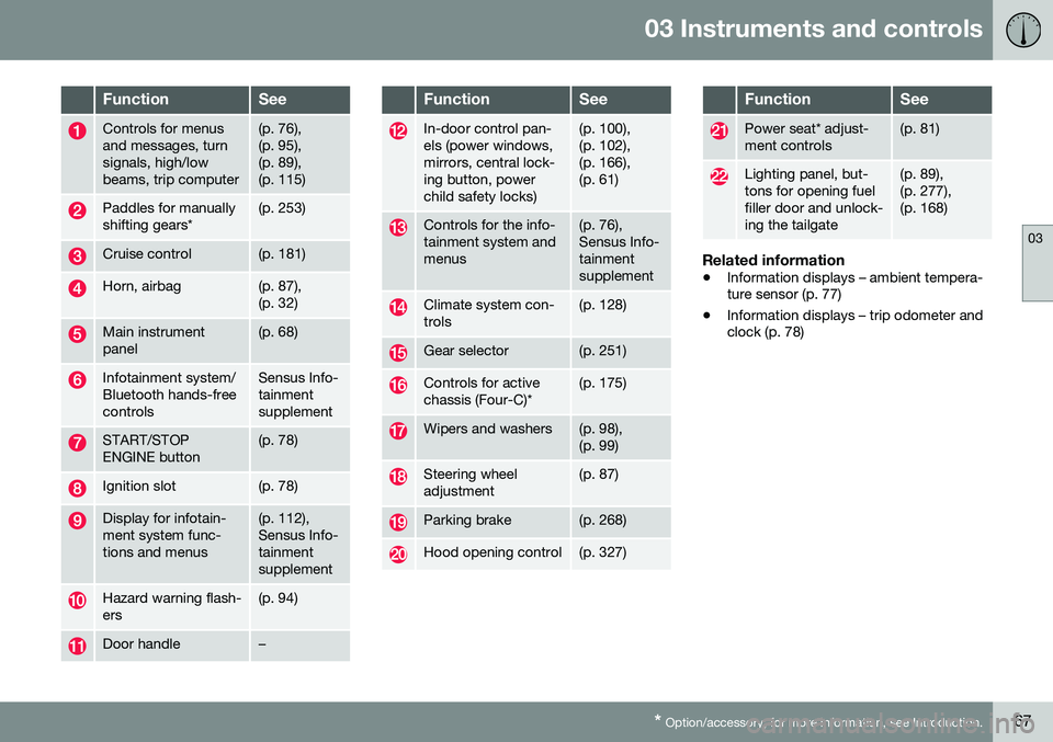
FunctionSee
Controls for menus and messages, turnsignals, high/lowbeams, trip computer(p. 76), (p. 95),(p. 89),(p. 115)
Paddles for manually shifting gears*(p. 253)
Cruise control(p. 181)
Horn, airbag(p. 87), (p. 32)
Main instrument panel(p. 68)
Infotainment system/ Bluetooth hands-freecontrolsSensus Info- tainmentsupplement
START/STOP ENGINE button(p. 78)
Ignition slot(p. 78)
Display for infotain- ment system func-tions and menus(p. 112), Sensus Info-tainmentsupplement
Hazard warning flash- ers(p. 94)
Door handle–
FunctionSee
In-door control pan- els (power windows,mirrors, central lock-ing button, powerchild safety locks)(p. 100), (p. 102),(p. 166),(p. 61)
Controls for the info- tainment system andmenus(p. 76), Sensus Info-tainmentsupplement
Climate system con- trols(p. 128)
Gear selector(p. 251)
Controls for active chassis (Four-C)*(p. 175)
Wipers and washers(p. 98), (p. 99)
Steering wheel adjustment(p. 87)
Parking brake(p. 268)
Hood opening control(p. 327)
FunctionSee
Power seat* adjust- ment controls(p. 81)
Lighting panel, but- tons for opening fuelfiller door and unlock-ing the tailgate(p. 89), (p. 277),(p. 168)
Related information
• Information displays – ambient tempera- ture sensor (p. 77)
• Information displays – trip odometer andclock (p. 78)
Page 74 of 396
||
03 Instruments and controls
03
72* Option/accessory, for more information, see Introduction.
Available powerThe smaller, upper indicator shows the engine's available power 2
. The higher the
reading on the scale, the greater the amount of power remaining in the current gear.
Utilized powerThe larger, lower indicator shows the amount of engine power that has been utilized 2
. The
higher the reading on the scale, the greater the amount of power that is being utilized. The larger the gap between the two indica- tors, the greater the amount of power remain-ing.
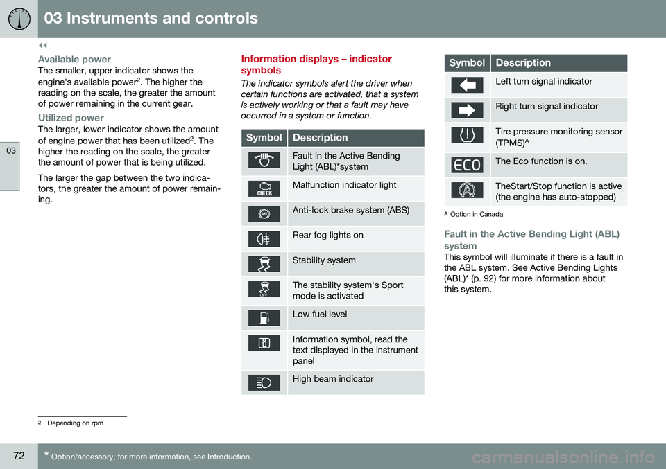
Information displays – indicator symbols
The indicator symbols alert the driver when certain functions are activated, that a systemis actively working or that a fault may haveoccurred in a system or function.
SymbolDescription
Fault in the Active Bending Light (ABL)*system
Malfunction indicator light
Anti-lock brake system (ABS)
Rear fog lights on
Stability system
The stability system's Sport mode is activated
Low fuel level
Information symbol, read the text displayed in the instrumentpanel
High beam indicator
SymbolDescription
Left turn signal indicator
Right turn signal indicator
Tire pressure monitoring sensor (TPMS) A
The Eco function is on.
TheStart/Stop function is active (the engine has auto-stopped)
A
Option in Canada
Fault in the Active Bending Light (ABL)
system
This symbol will illuminate if there is a fault in the ABL system. See Active Bending Lights(ABL)* (p. 92) for more information aboutthis system.
2 Depending on rpm
Page 79 of 396
03 Instruments and controls
03
* Option/accessory, for more information, see Introduction.77
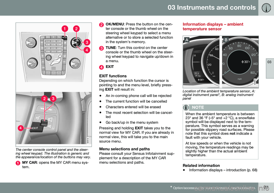
The center console control panel and the steer- ing wheel keypad. The illustration is generic andthe appearance/location of the buttons may vary.
MY CAR : opens the MY CAR menu sys-
tem.
OK/MENU : Press the button on the cen-
ter console or the thumb wheel on the steering wheel keypad to select a menualternative or to store a selected functionin the system's memory.
TUNE : Turn this control on the center
console or the thumb wheel on the steer- ing wheel keypad to navigate up/down ina menu.
EXIT
EXIT functionsDepending on which function the cursor is pointing to and the menu level, briefly press-ing EXIT will result in:
• An in-coming phone call will be rejected
• The current function will be cancelled
• Characters entered will be erased
• The most recent selection will be cancel- led
• Go back/up in the menu system
Pressing and holding EXIT takes you to the
normal view for MY CAR. If you are already in normal view, this will take you to the mainsource menu.
Menu selections and pathsPlease consult your Sensus Infotainment sup-plement for a description of the MY CARmenu selections and paths.
Information displays – ambient temperature sensor
Location of the ambient temperature sensor, A: digital instrument panel*, B: analog instrumentpanel
NOTE
When the ambient temperature is between 23° and 36 °F (–5° and +2 °C), a snowflakesymbol will be displayed next to the tem-perature. This symbol serves as a warningfor possible slippery road surfaces. Pleasenote that this symbol does not indicate a
fault with your vehicle. At low speeds or when the vehicle is not moving, the temperature readings may beslightly higher than the actual ambienttemperature.
Related information
• Information displays – introduction (p. 68)
Page 92 of 396
03 Instruments and controls
03
90* Option/accessory, for more information, see Introduction.
High/low beam headlights
When the engine is started, the low beams are activated automatically if the headlight control is in position
.
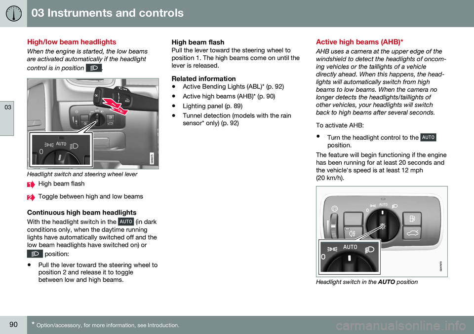
Headlight switch and steering wheel lever
High beam flash
Toggle between high and low beams
Continuous high beam headlights
With the headlight switch in the (in dark
conditions only, when the daytime running lights have automatically switched off and thelow beam headlights have switched on) or
position:
• Pull the lever toward the steering wheel to position 2 and release it to togglebetween low and high beams.
High beam flashPull the lever toward the steering wheel to position 1. The high beams come on until thelever is released.
Related information
•Active Bending Lights (ABL)* (p. 92)
• Active high beams (AHB)* (p. 90)
• Lighting panel (p. 89)
• Tunnel detection (models with the rain sensor* only) (p. 92)
Active high beams (AHB)*
AHB uses a camera at the upper edge of the windshield to detect the headlights of oncom-ing vehicles or the taillights of a vehicledirectly ahead. When this happens, the head-lights will automatically switch from highbeams to low beams. When the camera nolonger detects the headlights/taillights ofother vehicles, your headlights will switchback to high beams after several seconds. To activate AHB:
• Turn the headlight control to the
position.
The feature will begin functioning if the engine has been running for at least 20 seconds andthe vehicle's speed is at least 12 mph(20 km/h).
Headlight switch in the AUTO position