fuel VOLVO XC70 2016 Owner´s Manual
[x] Cancel search | Manufacturer: VOLVO, Model Year: 2016, Model line: XC70, Model: VOLVO XC70 2016Pages: 396, PDF Size: 10.01 MB
Page 9 of 396
Contents
7
08
Brakes – general..................................... 265
Brakes – symbols ................................... 267
Anti-lock braking system (ABS).............. 267
Brake lights............................................. 267
Emergency Brake Assistance (EBA)....... 268
Parking brake – general information....... 268
Parking brake – applying........................ 269
Parking brake – releasing........................ 270
Parking brake – symbols and messages 271
Driving through water.............................. 272
Engine and cooling system..................... 273
Conserving electrical current.................. 273
Before a long distance trip...................... 273
Driving in cold weather........................... 274
Refueling – fuel requirements................. 275
Refueling – octane rating........................ 276Refueling – opening/closing fuel filler
door......................................................... 277
Refueling – opening/closing fuel cap...... 278
Emission controls.................................... 279
Economical driving.................................. 279
Towing a trailer....................................... 281
Detachable trailer hitch........................... 282
Trailer Stability Assist (TSA).................... 283
08
Towing the vehicle.................................. 284
Towing eyelet.......................................... 284
Towing by tow truck............................... 285
09
09 Wheels and tires
Tires – general information...................... 288
Tires – storage and age.......................... 289
Tires – tread wear indicator.................... 290
Tires – tire economy................................ 290
Changing a wheel – direction of rotation 291
Changing a wheel – removing wheel...... 291
Changing a wheel – spare wheel............ 294Changing a wheel – accessing the spare
wheel....................................................... 295
Changing a wheel – installing a wheel.... 295
Tire inflation – general information.......... 296
Tire inflation – checking pressure........... 297
Tire specifications................................... 298
Tire inflation – pressure table.................. 300
Loading specifications............................ 301
Loading specifications – load limit.......... 301
Tire specifications – terminology............ 302Tire specifications – Uniform Tire Quality
Grading................................................... 303
Snow chains............................................ 304
Snow tires/studded tires......................... 305
Tire pressure monitoring - introduction.. 305Tire Pressure Monitoring System (TPMS)
– general information.............................. 306
Page 11 of 396
Contents
9
11
11 Specifications
Label information.................................... 367
Dimensions............................................. 370
Weights................................................... 372
Engine specifications.............................. 373
Oil specifications..................................... 374
Oil volume............................................... 375
Coolant – specification and volume........ 376Transmission oil – specification and vol-
umes....................................................... 376
Brake fluid – specification and volume... 376
Power steering – specification................ 377Fuel tank volume – specification and vol-
ume......................................................... 377 Air conditioning – specification and vol-
ume......................................................... 377
Battery specifications............................. 378
Symbols – general information............... 379
Warning symbols.................................... 379
Indicator symbols.................................... 380
Information symbols............................... 381
Information symbols – ceiling console.... 382
Information symbols – center console.... 382
12
12 Index
Index....................................................... 384
Page 19 of 396
01 Introduction
01
17
WARNING
If your vehicle is involved in an accident, unseen damage may affect its drivabilityand safety.
WARNING
CALIFORNIA proposition 65 Engine exhaust, some of its constituents, and certain vehicle components contain oremit chemicals known to the state of Cali-fornia to cause cancer, and birth defectsor other reproductive harm. In addition,certain fluids contained in vehicles andcertain products of component wear con-tain or emit chemicals known to the Stateof California to cause cancer, and birthdefects or other reproductive harm.
WARNING
Certain components of this vehicle such as air bag modules, seat belt pretensioners,adaptive steering columns, and button cellbatteries may contain Perchlorate material.Special handling may apply for service orvehicle end of life disposal. See www.dtsc.ca.gov/hazardouswaste/ perchlorate.
ShiftlockWhen your vehicle is parked, the gear selec- tor is locked in the P (Park) position. To
release the selector from this position, the ignition must be in mode
II (p. 79) or the
engine must be running. Depress the brakepedal, press the button on the front side ofthe gear selector and move the selector fromP (Park).
Anti-lock Brake System (ABS)The ABS system performs a brief self-diag-nostic test when the engine has been startedand driver releases the brake pedal. Anotherautomatic test may be performed when thevehicle first reaches a speed of approximately6 mph (10 km/h). The brake pedal will pulsateseveral times and a sound may be audiblefrom the ABS control module. This is normal.
Fuel filler doorPress the button on the light switch panel(see the illustration in Refueling – opening/closing fuel filler door (p. 277)) when the vehi-cle is at a standstill to unlock the fuel fillerdoor. It will relock when closed and there willbe an audible click.
Points to keep in mind
• Do not export your Volvo to another country before investigating that coun-try's applicable safety and exhaust emis-sion requirements. In some cases it maybe difficult or impossible to comply withthese requirements. Modifications to theemission control system(s) may renderyour Volvo not certifiable for legal opera- tion in the U.S., Canada and other coun-tries.
• All information, illustrations and specifica-tions contained in this manual are basedon the latest product information availa-ble at the time of publication. Please notethat some vehicles may be equipped dif-ferently, depending on special legalrequirements. Optional equipment descri-bed in this manual may not be available inall markets.
• Some of the illustrations shown aregeneric and may not depict the exactmodel for which this manual is intended.
• Volvo reserves the right to make modelchanges at any time, or to change speci-fications or design without notice andwithout incurring obligation.
Related information
• Information on the Internet (p. 20)
• Volvo and the environment (p. 22)
• Important warnings (p. 23)
Page 24 of 396
01 Introduction
01
22
Volvo and the environment
Volvo is committed to the well being of its customers. As a natural part of this commit-ment, we care about the environment inwhich we all live. Concern for the environmentmeans an everyday involvement in reducingour environmental impact. Volvo's environmental activities are based on a holistic view, which means we consider theoverall environmental impact of a productthroughout its complete life cycle. In this con-text, design, production, product use, andrecycling are all important considerations. Inproduction, Volvo has partly or completelyphased out several chemicals includingCFCs, lead chromates, asbestos, and cad-mium; and reduced the number of chemicalsused in our plants 50% since 1991. Volvo was the first in the world to introduce into production a three-way catalytic con-verter with a Lambda sond, now called theheated oxygen sensor, in 1976. The currentversion of this highly efficient system reducesemissions of harmful substances (CO, HC,NOx) from the exhaust pipe by approximately95 – 99% and the search to eliminate theremaining emissions continues. Volvo is theonly automobile manufacturer to offer CFC-free retrofit kits for the air conditioning systemof all models as far back as the 1975model 240. Advanced electronic engine con-trols and cleaner fuels are bringing us closerto our goal. In addition to continuous environ-mental refinement of conventional gasoline-powered internal combustion engines, Volvois actively looking at advanced technologyalternative-fuel vehicles. When you drive a Volvo, you become our partner in the work to lessen the car's impacton the environment. To reduce your vehicle'senvironmental impact, you can: •
Maintain proper air pressure in your tires. Tests have shown decreased fuel econ-omy with improperly inflated tires.
• Follow the recommended maintenanceschedule in your Warranty and ServiceRecords Information booklet.
• Drive at a constant speed whenever pos-sible.
• See a trained and qualified Volvo servicetechnician as soon as possible forinspection if the check engine (malfunc-tion indicator) light illuminates, or stayson after the vehicle has started.
• Properly dispose of any vehicle-relatedwaste such as used motor oil, used bat-teries, brake pads, etc.
• When cleaning your vehicle, please usegenuine Volvo car care products. AllVolvo car care products are formulated tobe environmentally friendly.
FSC®
The FSC ®
(Forest Stewardship Council ®
)
symbol indicates that the wood pulp used in this publication comes from FSC ®
certified
forests and other responsible sources.
Related information
• Economical driving (p. 279)
• Tires – tire economy (p. 290)
Page 46 of 396
02 Safety
02
44* Option/accessory, for more information, see Introduction.
Crash mode – general information
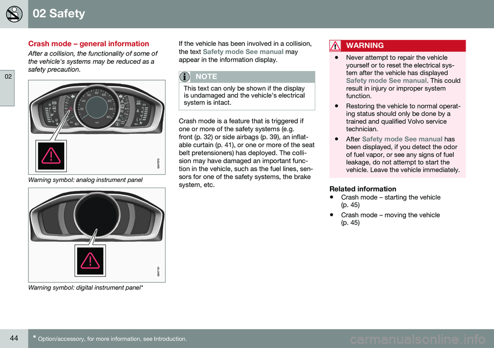
After a collision, the functionality of some of the vehicle's systems may be reduced as asafety precaution.
Warning symbol: analog instrument panel
Warning symbol: digital instrument panel* If the vehicle has been involved in a collision, the text
Safety mode See manual may
appear in the information display.
NOTE
This text can only be shown if the display is undamaged and the vehicle's electricalsystem is intact.
Crash mode is a feature that is triggered if one or more of the safety systems (e.g.front (p. 32) or side airbags (p. 39), an inflat-able curtain (p. 41), or one or more of the seatbelt pretensioners) has deployed. The colli-sion may have damaged an important func-tion in the vehicle, such as the fuel lines, sen-sors for one of the safety systems, the brakesystem, etc.
WARNING
• Never attempt to repair the vehicle yourself or to reset the electrical sys-tem after the vehicle has displayed
Safety mode See manual. This could
result in injury or improper system function.
• Restoring the vehicle to normal operat-ing status should only be done by atrained and qualified Volvo servicetechnician.
• After
Safety mode See manual has
been displayed, if you detect the odor of fuel vapor, or see any signs of fuelleakage, do not attempt to start thevehicle. Leave the vehicle immediately.
Related information
• Crash mode – starting the vehicle (p. 45)
• Crash mode – moving the vehicle(p. 45)
Page 47 of 396
02 Safety
02
}}
45
Crash mode – starting the vehicle
If Crash mode has been set Crash mode (p. 44)) and damage to the vehicle isminor and there is no fuel leakage, you mayattempt to start the engine. To do so:
1. Remove the remote key from the ignitionslot and open the driver's door. If a mes- sage is displayed that the ignition is on,press the start button.
2. Close the driver's door and reinsert the remote key in the ignition slot.
3. Try to start the vehicle.
WARNING
If the message Safety mode See manualis still displayed, the vehicle should not be driven and must be towed. Concealedfaults may make the vehicle difficult tocontrol.
Related information
• Crash mode – general information (p. 44)
• Crash mode – moving the vehicle (p. 45)
Crash mode – moving the vehicle
If the message Normal mode appears after
an attempt has been made to start the engine, Starting the vehicle after a crash (p. 45), thevehicle may be moved carefully from its pres-ent position, if for example, it is blocking traf-fic. It should, however, not be moved fartherthan is absolutely necessary.
WARNING
Even if the vehicle appears to be drivable after Crash mode has been set, it shouldnot be driven or towed (pulled by anothervehicle). There may be concealed damagethat could make it difficult or impossible tocontrol. The vehicle should be transportedon a flatbed tow truck to a trained andqualified Volvo service technician forinspection/repairs.
Related information
• Crash mode – general information (p. 44)
Child safety
Children should always be seated safely when traveling in the vehicle.
General informationVolvo recommends the proper use of restraintsystems (p. 47) for all occupants includingchildren. Remember that, regardless of ageand size, a child should always be properlyrestrained in a vehicle. Your vehicle is also equipped with ISOFIX/ LATCH attachments (p. 54), which make itmore convenient to install child seats. Some restraint systems for children are designed to be secured in the vehicle by lapbelts or the lap portion of a lap-shoulder belt.Such child restraint systems can help protectchildren in vehicles in the event of an acci-dent only if they are used properly. However,children could be endangered in a crash if thechild restraints are not properly secured in thevehicle. Failure to follow the installationinstructions for your child restraint can resultin your child striking the vehicle's interior in asudden stop. Holding a child in your arms is NOT a suitable substitute for a child restraint system. In anaccident, a child held in a person's arms canbe crushed between the vehicle's interior andan unrestrained person. The child could alsobe injured by striking the interior, or by beingejected from the vehicle during a suddenmaneuver or impact. The same can also hap-
Page 69 of 396
03 Instruments and controls
03
* Option/accessory, for more information, see Introduction.67
FunctionSee
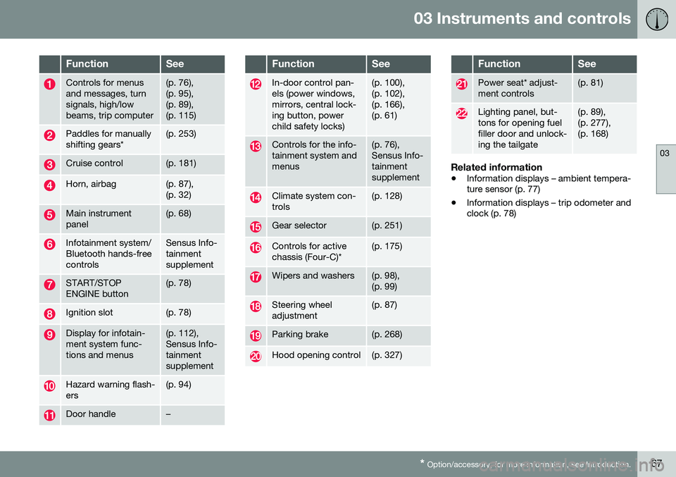
Controls for menus and messages, turnsignals, high/lowbeams, trip computer(p. 76), (p. 95),(p. 89),(p. 115)
Paddles for manually shifting gears*(p. 253)
Cruise control(p. 181)
Horn, airbag(p. 87), (p. 32)
Main instrument panel(p. 68)
Infotainment system/ Bluetooth hands-freecontrolsSensus Info- tainmentsupplement
START/STOP ENGINE button(p. 78)
Ignition slot(p. 78)
Display for infotain- ment system func-tions and menus(p. 112), Sensus Info-tainmentsupplement
Hazard warning flash- ers(p. 94)
Door handle–
FunctionSee
In-door control pan- els (power windows,mirrors, central lock-ing button, powerchild safety locks)(p. 100), (p. 102),(p. 166),(p. 61)
Controls for the info- tainment system andmenus(p. 76), Sensus Info-tainmentsupplement
Climate system con- trols(p. 128)
Gear selector(p. 251)
Controls for active chassis (Four-C)*(p. 175)
Wipers and washers(p. 98), (p. 99)
Steering wheel adjustment(p. 87)
Parking brake(p. 268)
Hood opening control(p. 327)
FunctionSee
Power seat* adjust- ment controls(p. 81)
Lighting panel, but- tons for opening fuelfiller door and unlock-ing the tailgate(p. 89), (p. 277),(p. 168)
Related information
• Information displays – ambient tempera- ture sensor (p. 77)
• Information displays – trip odometer andclock (p. 78)
Page 70 of 396
03 Instruments and controls
03
68* Option/accessory, for more information, see Introduction.
Information displays – introduction
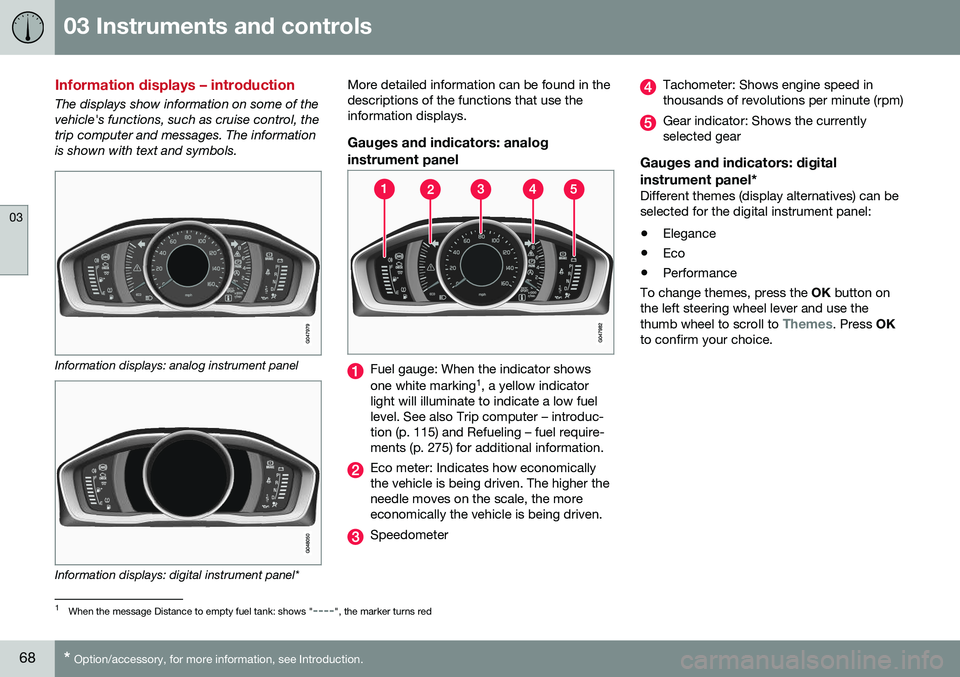
The displays show information on some of the vehicle's functions, such as cruise control, thetrip computer and messages. The informationis shown with text and symbols.
Information displays: analog instrument panel
Information displays: digital instrument panel* More detailed information can be found in the descriptions of the functions that use theinformation displays.
Gauges and indicators: analog
instrument panel
Fuel gauge: When the indicator shows one white marking 1
, a yellow indicator
light will illuminate to indicate a low fuel level. See also Trip computer – introduc-tion (p. 115) and Refueling – fuel require-ments (p. 275) for additional information.
Eco meter: Indicates how economically the vehicle is being driven. The higher theneedle moves on the scale, the moreeconomically the vehicle is being driven.
Speedometer
Tachometer: Shows engine speed in thousands of revolutions per minute (rpm)
Gear indicator: Shows the currently selected gear
Gauges and indicators: digital instrument panel*
Different themes (display alternatives) can be selected for the digital instrument panel: • Elegance
• Eco
• Performance
To change themes, press the OK button on
the left steering wheel lever and use the thumb wheel to scroll to
Themes. Press OK
to confirm your choice.
1 When the message Distance to empty fuel tank: shows "----", the marker turns red
Page 71 of 396
03 Instruments and controls
03
}}
* Option/accessory, for more information, see Introduction.69
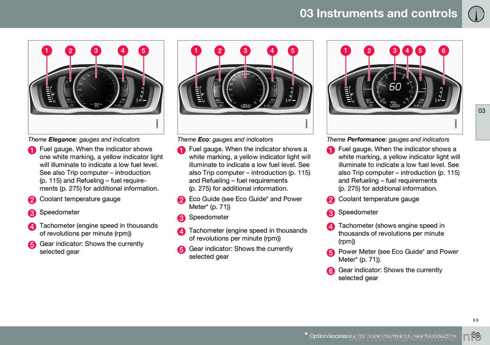
Theme Elegance : gauges and indicators
Fuel gauge. When the indicator shows one white marking, a yellow indicator lightwill illuminate to indicate a low fuel level.See also Trip computer – introduction(p. 115) and Refueling – fuel require-ments (p. 275) for additional information.
Coolant temperature gauge
Speedometer
Tachometer (engine speed in thousands of revolutions per minute (rpm))
Gear indicator: Shows the currently selected gear
Theme Eco: gauges and indicators
Fuel gauge. When the indicator shows a white marking, a yellow indicator light willilluminate to indicate a low fuel level. Seealso Trip computer – introduction (p. 115)and Refueling – fuel requirements(p. 275) for additional information.
Eco Guide (see Eco Guide* and Power Meter* (p. 71))
Speedometer
Tachometer (engine speed in thousands of revolutions per minute (rpm))
Gear indicator: Shows the currently selected gear
Theme Performance : gauges and indicators
Fuel gauge. When the indicator shows a white marking, a yellow indicator light willilluminate to indicate a low fuel level. Seealso Trip computer – introduction (p. 115)and Refueling – fuel requirements(p. 275) for additional information.
Coolant temperature gauge
Speedometer
Tachometer (shows engine speed in thousands of revolutions per minute(rpm))
Power Meter (see Eco Guide* and Power Meter* (p. 71)).
Gear indicator: Shows the currently selected gear
Page 74 of 396
||
03 Instruments and controls
03
72* Option/accessory, for more information, see Introduction.
Available powerThe smaller, upper indicator shows the engine's available power 2
. The higher the
reading on the scale, the greater the amount of power remaining in the current gear.
Utilized powerThe larger, lower indicator shows the amount of engine power that has been utilized 2
. The
higher the reading on the scale, the greater the amount of power that is being utilized. The larger the gap between the two indica- tors, the greater the amount of power remain-ing.
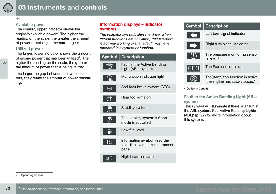
Information displays – indicator symbols
The indicator symbols alert the driver when certain functions are activated, that a systemis actively working or that a fault may haveoccurred in a system or function.
SymbolDescription
Fault in the Active Bending Light (ABL)*system
Malfunction indicator light
Anti-lock brake system (ABS)
Rear fog lights on
Stability system
The stability system's Sport mode is activated
Low fuel level
Information symbol, read the text displayed in the instrumentpanel
High beam indicator
SymbolDescription
Left turn signal indicator
Right turn signal indicator
Tire pressure monitoring sensor (TPMS) A
The Eco function is on.
TheStart/Stop function is active (the engine has auto-stopped)
A
Option in Canada
Fault in the Active Bending Light (ABL)
system
This symbol will illuminate if there is a fault in the ABL system. See Active Bending Lights(ABL)* (p. 92) for more information aboutthis system.
2 Depending on rpm