VOLVO XC90 2014 Owner´s Manual
Manufacturer: VOLVO, Model Year: 2014, Model line: XC90, Model: VOLVO XC90 2014Pages: 308, PDF Size: 13.31 MB
Page 51 of 308

01 Safety
ISOFIX/LATCH lower anchors01
49
Using the ISOFIX/LATCH lower child seat anchors
G015268
ISOFIX/LATCH lower child restraint anchorsLower anchors for ISOFIX/LATCH-equipped child seats are located in the second row,outboard seats, hidden below the backrestcushions. Symbols on the seat back uphols-tery mark the anchor positions (see the illus-tration).
To access the anchors:1. Put the child restraint in position.
2. Kneel on the child restraint to press down the seat cushion and locate the anchors by feel. 3. Fasten the attachment on the child
restraint's lower straps to the ISOFIX/LATCH lower anchors.
4. Firmly tension the lower child seat straps according to the manufacturer's instruc-tions.
WARNING
Volvo's ISOFIX/LATCH anchors conform to FMVSS/CMVSS standards. Always refer tothe child restraint system's manual forweight and size ratings.
WARNING
The ISOFIX/LATCH lower child restraint anchors are only intended for use withchild seats positioned in the outboardseating positions. These anchors are notcertified for use with any child restraintthat is positioned in the center seatingposition. When securing a child restraint inthe center seating position, use only thevehicle's center seat belt.
NOTE
•The rear seat's center position is not equipped with ISOFIX/LATCH loweranchors. When installing a childrestraint in this position, attach therestraint's top tether strap (if it is soequipped) to the top tether anchoragepoint and secure the restraint with thevehicle's center seat belt.
• Always follow your child seat manufac-turer's installation instructions, anduse both ISOFIX/LATCH lower anchorsand top tethers whenever possible.
G031682
Fasten the attachment correctly to the ISOFIX/ LATCH lower anchors
Page 52 of 308
01 Safety
ISOFIX/LATCH lower anchors 01
50
WARNING
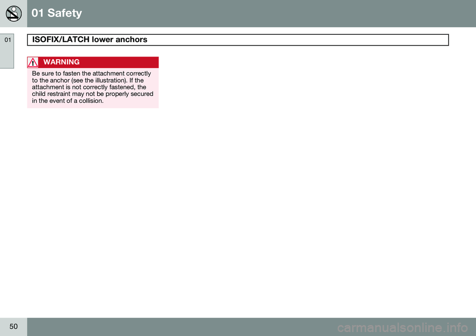
Be sure to fasten the attachment correctly to the anchor (see the illustration). If theattachment is not correctly fastened, thechild restraint may not be properly securedin the event of a collision.
Page 53 of 308
01 Safety
Top tether anchors01
51
Top tether anchors
G027032
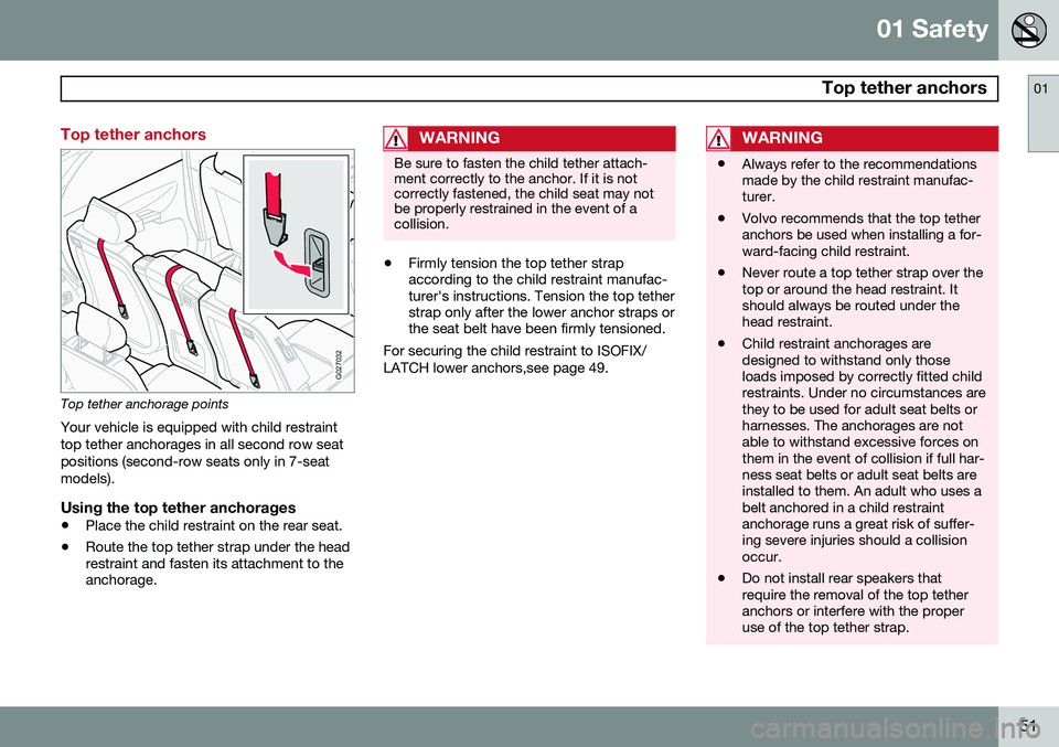
Top tether anchorage points
Your vehicle is equipped with child restraint top tether anchorages in all second row seatpositions (second-row seats only in 7-seatmodels).
Using the top tether anchorages
• Place the child restraint on the rear seat.
• Route the top tether strap under the head restraint and fasten its attachment to theanchorage.
WARNING
Be sure to fasten the child tether attach- ment correctly to the anchor. If it is notcorrectly fastened, the child seat may notbe properly restrained in the event of acollision.
•Firmly tension the top tether strap according to the child restraint manufac-turer's instructions. Tension the top tetherstrap only after the lower anchor straps orthe seat belt have been firmly tensioned.
For securing the child restraint to ISOFIX/ LATCH lower anchors,see page 49.
WARNING
• Always refer to the recommendations made by the child restraint manufac-turer.
• Volvo recommends that the top tetheranchors be used when installing a for-ward-facing child restraint.
• Never route a top tether strap over thetop or around the head restraint. Itshould always be routed under thehead restraint.
• Child restraint anchorages aredesigned to withstand only thoseloads imposed by correctly fitted childrestraints. Under no circumstances arethey to be used for adult seat belts orharnesses. The anchorages are notable to withstand excessive forces onthem in the event of collision if full har-ness seat belts or adult seat belts areinstalled to them. An adult who uses abelt anchored in a child restraintanchorage runs a great risk of suffer-ing severe injuries should a collisionoccur.
• Do not install rear speakers thatrequire the removal of the top tetheranchors or interfere with the properuse of the top tether strap.
Page 54 of 308
01 Safety
Integrated booster cushion 01
52* Option/accessory, for more information, see Introduction.
Integrated booster cushion*
G031071
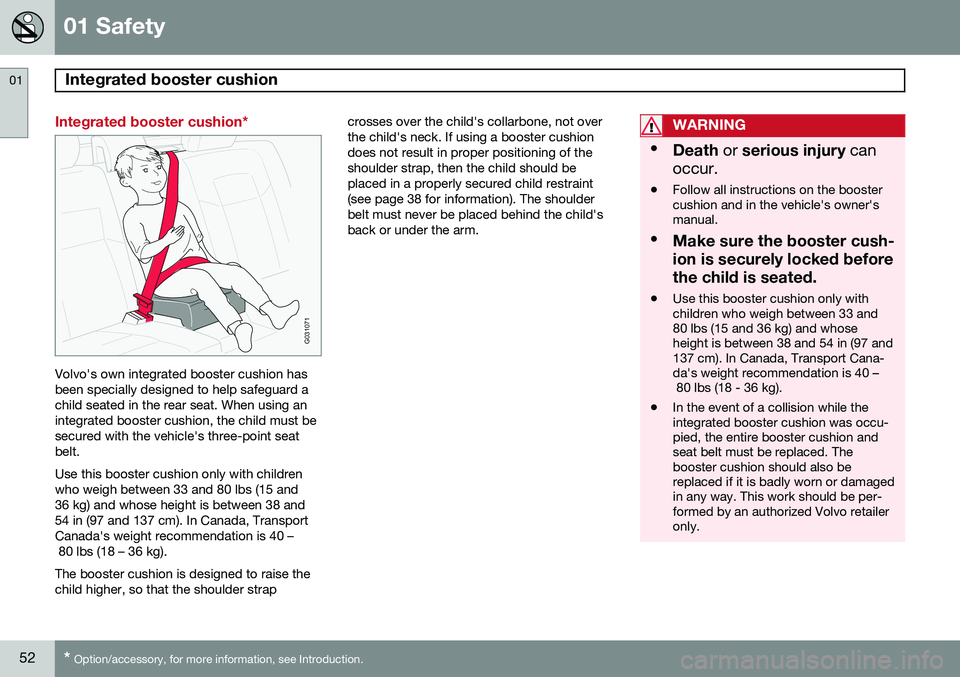
Volvo's own integrated booster cushion has been specially designed to help safeguard achild seated in the rear seat. When using anintegrated booster cushion, the child must besecured with the vehicle's three-point seatbelt. Use this booster cushion only with children who weigh between 33 and 80 lbs (15 and36 kg) and whose height is between 38 and54 in (97 and 137 cm). In Canada, TransportCanada's weight recommendation is 40 – 80 lbs (18 – 36 kg). The booster cushion is designed to raise the child higher, so that the shoulder strap crosses over the child's collarbone, not overthe child's neck. If using a booster cushiondoes not result in proper positioning of theshoulder strap, then the child should beplaced in a properly secured child restraint(see page 38 for information). The shoulderbelt must never be placed behind the child'sback or under the arm.
WARNING
•
Death or serious injury can
occur.
• Follow all instructions on the booster cushion and in the vehicle's owner'smanual.
• Make sure the booster cush- ion is securely locked beforethe child is seated.
• Use this booster cushion only with children who weigh between 33 and80 lbs (15 and 36 kg) and whoseheight is between 38 and 54 in (97 and137 cm). In Canada, Transport Cana-da's weight recommendation is 40 – 80 lbs (18 - 36 kg).
• In the event of a collision while theintegrated booster cushion was occu-pied, the entire booster cushion andseat belt must be replaced. Thebooster cushion should also bereplaced if it is badly worn or damagedin any way. This work should be per-formed by an authorized Volvo retaileronly.
Page 55 of 308
01 Safety
Integrated booster cushion01
53
NOTE
Canada only: This cushion may be referred to as a built-in booster cushion.
G030708
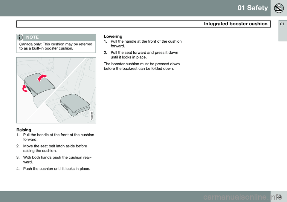
Raising1. Pull the handle at the front of the cushionforward.
2. Move the seat belt latch aside before raising the cushion.
3. With both hands push the cushion rear- ward.
4. Push the cushion until it locks in place.
Lowering1. Pull the handle at the front of the cushion forward.
2. Pull the seat forward and press it down until it locks in place.
The booster cushion must be pressed down before the backrest can be folded down.
Page 56 of 308
54* Option/accessory, for more information, see Introduction. Instrument overview................................................................................ 56 Instrument panel..................................................................................... 58Information display.................................................................................. 62
Center console buttons........................................................................... 64
Steering wheel adjustment..................................................................... 66Lighting panel.......................................................................................... 67
Manually unlocking the fuel filler door.................................................... 70
Left-side steering wheel lever................................................................. 71
Right-side steering wheel lever............................................................... 72
Hazard warning flashers......................................................................... 75Trip computer.......................................................................................... 76Cruise control.......................................................................................... 7812-volt sockets....................................................................................... 80Hood/tailgate.......................................................................................... 81
Power windows.......................................................................................82Mirrors..................................................................................................... 84
Power moonroof..................................................................................... 87 HomeLink
®
Wireless Control System*.................................................... 89
Page 57 of 308
I N S T R U M E N T S A N D C O N T R O L S
Page 58 of 308
02 Instruments and controls
Instrument overview
02
56
Page 59 of 308
02 Instruments and controls
Instrument overview
02
* Option/accessory, for more information, see Introduction.57
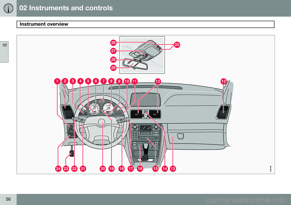
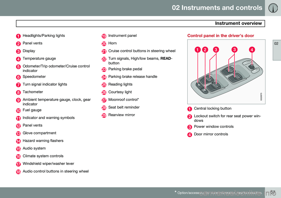
Headlights/Parking lights
Panel vents
Display
Temperature gauge
Odometer/Trip odometer/Cruise control indicator
Speedometer
Turn signal indicator lights
Tachometer
Ambient temperature gauge, clock, gear indicator
Fuel gauge
Indicator and warning symbols
Panel vents
Glove compartment
Hazard warning flashers
Audio system
Climate system controls
Windshield wiper/washer lever
Audio control buttons in steering wheel
Instrument panel
Horn
Cruise control buttons in steering wheel
Turn signals, High/low beams, READ-
button
Parking brake pedal
Parking brake release handle
Reading lights
Courtesy light
Moonroof control*
Seat belt reminder
Rearview mirror
Control panel in the driver's door
G029570
Central locking button
Lockout switch for rear seat power win- dows
Power window controls
Door mirror controls
Page 60 of 308
02 Instruments and controls
Instrument panel
02
58
Instrument panel
G027133
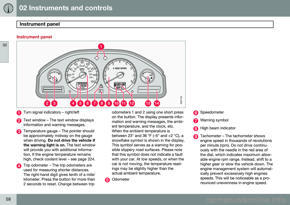
Turn signal indicators – right/left
Text window – The text window displays information and warning messages.
Temperature gauge – The pointer should be approximately midway on the gaugewhen driving. Do not drive the vehicle if
the warning light is on. The text window
will provide you with additional informa-tion. If the engine temperature remainshigh, check coolant level – see page 224.
Trip odometer – The trip odometers are used for measuring shorter distances.The right-hand digit gives tenth of a mile/kilometer. Press the button for more than2 seconds to reset. Change between trip odometers 1 and 2 using one short presson the button. The display presents infor-mation and warning messages, the ambi-ent temperature, and the clock, etc.When the ambient temperature isbetween 23° and 36 °F (–5° and +2 °C), asnowflake symbol is shown in the display.This symbol serves as a warning for pos-sible slippery road surfaces. Please notethat this symbol does not indicate a faultwith your car. At low speeds, or when thecar is not moving, the temperature read-ings may be slightly higher than theactual ambient temperature.
Odometer
Speedometer
Warning symbol
High beam indicator
Tachometer – The tachometer shows engine speed in thousands of revolutionsper minute (rpm). Do not drive continu-ously with the needle in the red area ofthe dial, which indicates maximum allow-able engine rpm range. Instead, shift to ahigher gear or slow the vehicle down. Theengine management system will automat-ically prevent excessively high enginesspeeds. This will be noticeable as a pro-nounced unevenness in engine speed.