wiring VOLVO XC90 2015 Owners Manual
[x] Cancel search | Manufacturer: VOLVO, Model Year: 2015, Model line: XC90, Model: VOLVO XC90 2015Pages: 570, PDF Size: 12.44 MB
Page 90 of 570

SAFETY
88
Side impact airbags
As an enhancement to the structural side impact protection built into your vehicle, it is also equip-ped with Side Impact Protection System (SIPS)airbags.
The SIPS airbag system is designed to help increase occupant protection in the event of cer-tain side impact collisions. The SIPS airbags aredesigned to deploy only during certain side-impact collisions, depending on the crashseverity, angle, speed and point of impact.
NOTE
SIPS airbag deployment (one airbag) occurs only on the side of the vehicle affected by theimpact. The airbags are not designed todeploy in all side impact situations.
Components in the SIPS airbag systemThis SIPS airbag system consists of a gas gener- ator, the side airbag modules built into the out-board sides of both front seat backrests, andelectronic sensors/wiring.
WARNING
• The SIPS airbag system is a supplement to the structural Side Impact ProtectionSystem and the three-point seat belt sys-tem. It is not designed to deploy duringcollisions from the front or rear of thevehicle or in rollover situations.
• The use of seat covers on the front seatsmay impede SIPS airbag deployment.
• No objects, accessory equipment or stick-ers may be placed on, attached to orinstalled near the SIPS airbag system orin the area affected by SIPS airbagdeployment.
• Never try to open or repair any compo-nents of the SIPS airbag system. Thisshould be done only by a trained andqualified Volvo service technician.
• In order for the SIPS airbag to provide itsbest protection, both front seat occupantsshould sit in an upright position with theseat belt properly fastened.
• Failure to follow these instructions canresult in injury to the occupants of thevehicle in the event of an accident.
Related information
• Airbag system (p. 83)
• Seat belts (p. 58)
Page 293 of 570

DRIVER SUPPORT
* Option/accessory, for more information, see Introduction.291
Road Sign Assistance (RSI)*
operation
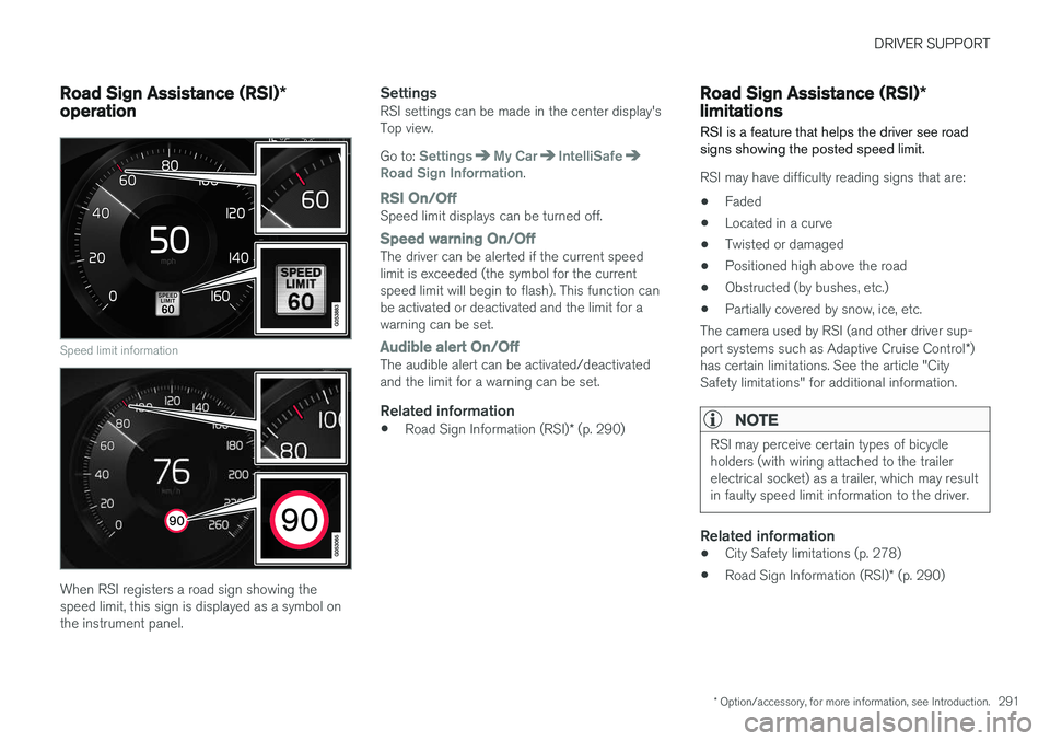
Speed limit information
When RSI registers a road sign showing the speed limit, this sign is displayed as a symbol onthe instrument panel.
SettingsRSI settings can be made in the center display'sTop view. Go to:
SettingsMy CarIntelliSafeRoad Sign Information.
RSI On/OffSpeed limit displays can be turned off.
Speed warning On/OffThe driver can be alerted if the current speed limit is exceeded (the symbol for the currentspeed limit will begin to flash). This function canbe activated or deactivated and the limit for awarning can be set.
Audible alert On/OffThe audible alert can be activated/deactivated and the limit for a warning can be set.
Related information
• Road Sign Information (RSI)
* (p. 290)
Road Sign Assistance (RSI) *
limitations
RSI is a feature that helps the driver see road signs showing the posted speed limit.
RSI may have difficulty reading signs that are:
• Faded
• Located in a curve
• Twisted or damaged
• Positioned high above the road
• Obstructed (by bushes, etc.)
• Partially covered by snow, ice, etc.
The camera used by RSI (and other driver sup- port systems such as Adaptive Cruise Control *)
has certain limitations. See the article "City Safety limitations" for additional information.
NOTE
RSI may perceive certain types of bicycle holders (with wiring attached to the trailerelectrical socket) as a trailer, which may resultin faulty speed limit information to the driver.
Related information
• City Safety limitations (p. 278)
• Road Sign Information (RSI)
* (p. 290)
Page 296 of 570

DRIVER SUPPORT
* Option/accessory, for more information, see Introduction.
294
Park Assist limitations
The Park Assist system has certain limitations.
NOTE
A trailer hitch whose wiring is integrated with the vehicle's electrical system will be includedin the measurement of the available spacebehind the vehicle.
NOTE
• The system will not detect high objects, such as a loading dock, etc.
• Objects such as chains, thin shiny polesor low objects may temporarily not bedetected by the system. This may resultin the pulsing tone unexpectedly stoppinginstead of changing to a constant tone asthe vehicle approaches the object. Insuch cases, use caution when backing upor stop the vehicle to help avoid damage.
• In certain circumstances, the park assistsystem may give unexpected warning sig-nals that can be caused by externalsound sources that use the same ultra-sound frequencies as the system. Thismay include such things as the horns ofother vehicles, wet tires on asphalt, pneu-matic brakes, motorcycle exhaust pipes,etc. This does not indicate a fault in thesystem.
Cleaning the sensors
Location of the Park Assist sensors
The sensors must be cleaned regularly to ensure that they work properly. Clean them with waterand a suitable car washing detergent.
NOTE
If the sensors are obstructed by e.g., dirt, snow, or ice, this could result in false warningsignals from the park assist system.
Related information
•
Park Assist
* (p. 292)
• Activating/deactivating Park Assist (p. 293)
• Park assist symbols and messages (p. 295)
Page 298 of 570

DRIVER SUPPORT
* Option/accessory, for more information, see Introduction.
296
Park Assist Camera (PAC) *
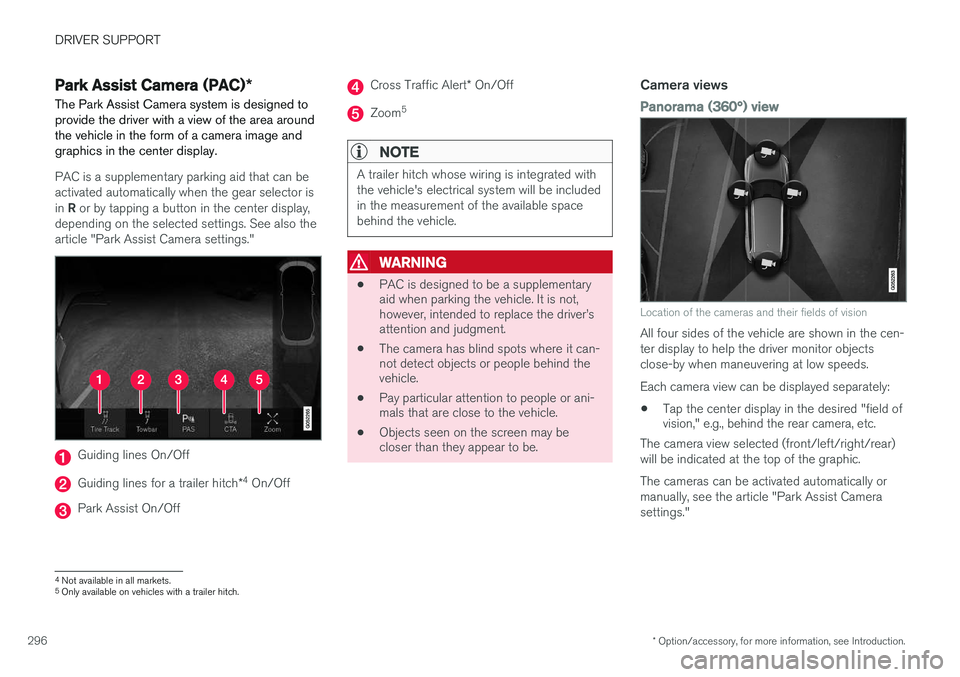
The Park Assist Camera system is designed to provide the driver with a view of the area aroundthe vehicle in the form of a camera image andgraphics in the center display.
PAC is a supplementary parking aid that can be activated automatically when the gear selector is in R or by tapping a button in the center display,
depending on the selected settings. See also the article "Park Assist Camera settings."
Guiding lines On/Off
Guiding lines for a trailer hitch *4
On/Off
Park Assist On/Off
Cross Traffic Alert * On/Off
Zoom 5
NOTE
A trailer hitch whose wiring is integrated with the vehicle's electrical system will be includedin the measurement of the available spacebehind the vehicle.
WARNING
•
PAC is designed to be a supplementary aid when parking the vehicle. It is not,however, intended to replace the driver
Page 322 of 570

DRIVER SUPPORT
* Option/accessory, for more information, see Introduction.
320
Cross Traffic Alert (CTA) * limitations
CTA functionality may be reduced in certain sit- uations.
LimitationsCTA has limitations in certain situations, for example, the CTA sensors cannot "see" throughother parked vehicles or obstructions. The following are several examples where CTA's "field of vision" may initially be limited andapproaching vehicles cannot be detected untilthey are too close:
The vehicle is pulled far into a parking space
In angled parking spaces, CTA may be "blind" on one side
CTA's blind area
CTA's "field of vision"
However, as you back your vehicle out of a park- ing space, CTA's "field of vision" expands. Examples of other limitations include:
• Dirt, ice or snow obstructing the sensors may reduce the system's function or make itimpossible to detect other vehicles orobjects.
• CTA is deactivated if a trailer's wiring is con-nected to the vehicle's electrical system.
MaintenanceThe CTA sensors are located on the inside of the rear fenders/bumper.
Keep the highlighted area clean (on both sides of the vehicle)
For the system to function optimally, the area over and around the sensors must be kept clean. Do not attach any objects, tape, decals, etc., on the surface of the sensors.
CAUTION
Repairs to the BLIS/CTA systems and/or repainting the rear bumper should only bedone by a trained and qualified Volvo servicetechnician.
Related information
•
Cross Traffic Alert (CTA)
* (p. 318)
• Activating/deactivating Cross Traffic Alert (CTA)
* (p. 319)
Page 342 of 570

STARTING AND DRIVING
340•
Remove snow tires when threat of snow or ice has ended.
• Note that roof racks, ski racks, etc, increaseair resistance and also fuel consumption.
• At highway driving speeds, fuel consumptionwill be lower with the air conditioning on andthe windows closed than with the air condi-tioning off and the windows open.
• Using the onboard trip computer's fuel con-sumption modes can help you learn how todrive more economically.
Other factors that decrease gas mileage are:
• Dirty air cleaner
• Dirty engine oil and clogged oil filter
• Dragging brakes
• Incorrect front end alignment
Some of the above mentioned items and others are checked at the standard maintenance inter-vals.
Handling and roadholding
• Vehicle load, tire design and inflation pres- sure all affect vehicle handling. Therefore,check that the tires are inflated to the rec-ommended pressure according to the vehicleload. Loads should be distributed so thatcapacity weight or maximum permissible axleloads are not exceeded.
• At the specified curb weight your vehicle hasa tendency to understeer, which means thatthe steering wheel has to be turned more than might seem appropriate for the curva-ture of a bend. This ensures good stabilityand reduces the risk of rear wheel skid.Remember that these properties can alterwith the vehicle load. The heavier the load inthe cargo compartment, the less the ten-dency to understeer.
Driving through standing water
The vehicle should be driven with extreme cau- tion if it is necessary to drive through standingwater.
The vehicle can be driven through water up to a depth of approximately 17.7 in. (45 cm) at walk-ing speed to help prevent water from enteringthe differential and the transmission. Thisreduces the oil's lubricating capacity and mayshorten the service life of these components.
• Take particular care when driving through flowing water.
• After driving through water, apply the brakesand check that they are functioning correctly.
• Clean the electrical connections for trailerwiring after driving in mud or water.
• When driving through water, maintain lowspeed and do not stop in the water.