rear seat VOLVO XC90 T8 2016 Owner´s Manual
[x] Cancel search | Manufacturer: VOLVO, Model Year: 2016, Model line: XC90 T8, Model: VOLVO XC90 T8 2016Pages: 546, PDF Size: 10.26 MB
Page 221 of 546
LOADING AND STORAGE
}}
* Option/accessory, for more information, see Introduction.219
CAUTION
Pressure from the front seats against the cargo net could damage the net and/or itsbrackets.
5. Pull the lower straps taut.
Removing and storing
1. Reduce tension on the net by pressing the
button on the lower straps' respective locks and allow some slack on both sides.
2. Press in the catches and release both of the straps' hooks.
3. Remove the upper hooks from the ceiling mounting points.
4. Press the red button on the upper rod to allow it to fold.
5. Fold and roll up the net. Store the net under the cargo compartment floor.
Related information
• Cargo compartment cover
* (p. 221)
• Load anchoring eyelets (p. 220)
• Steel cargo grid
* (p. 219)
• Loading (p. 215)
Steel cargo grid
*
Your vehicle can be equipped with a steel grid that helps prevent objects in the cargo area frommoving forward into the passenger compart-ment.
The steel grid is made up of the grid itself and two separate mounting brackets. Each of thebrackets has a screw cover and there are twoplastic sleeves for the grid.
WARNING
• No one should ever be allowed to remain in the cargo compartment when the vehi-cle is moving.
• The steel grid may only be used in therear position described in this article. Theceiling attachment points above the front seats are
not intended to anchor the
steel grid.
• The third row of seats (7-seat models
*
only): these seats must be folded down when the steel grid is mounted in thevehicle.
• After being mounted, be sure that thesteel grid is securely anchored in place.
Mounting1. Fold down the rear seats (second row of
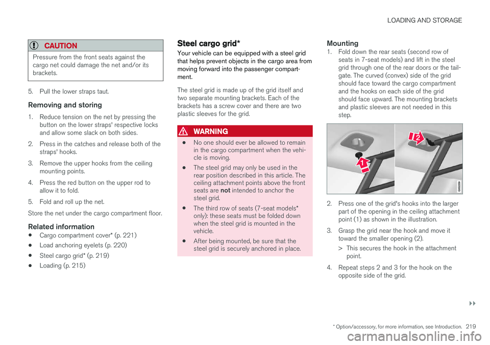
seats in 7-seat models) and lift in the steel grid through one of the rear doors or the tail-gate. The curved (convex) side of the gridshould face toward the cargo compartmentand the hooks on each side of the gridshould face upward. The mounting bracketsand plastic sleeves are not needed in thisstep.
2. Press one of the grid's hooks into the largerpart of the opening in the ceiling attachment point (1) as shown in the illustration.
3. Grasp the grid near the hook and move it toward the smaller opening (2).
> This secures the hook in the attachmentpoint.
4. Repeat steps 2 and 3 for the hook on the opposite side of the grid.
Page 223 of 546
LOADING AND STORAGE
}}
* Option/accessory, for more information, see Introduction.221
Related information
•Loading (p. 215)
Cargo compartment cover
*
The cover can be used to conceal objects in the cargo area.
Installing the cover 5
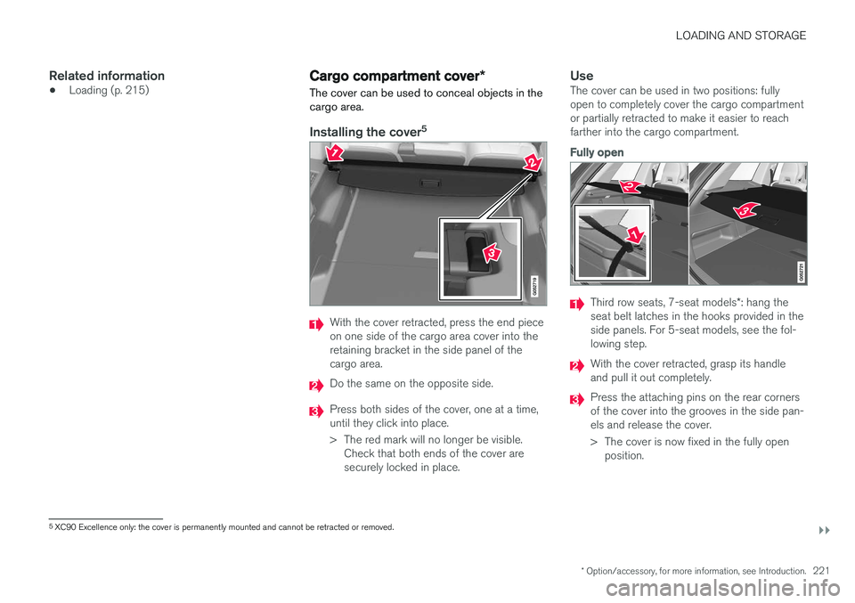
With the cover retracted, press the end piece on one side of the cargo area cover into theretaining bracket in the side panel of thecargo area.
Do the same on the opposite side.
Press both sides of the cover, one at a time, until they click into place.
> The red mark will no longer be visible.
Check that both ends of the cover are securely locked in place.
UseThe cover can be used in two positions: fullyopen to completely cover the cargo compartmentor partially retracted to make it easier to reachfarther into the cargo compartment.
Fully open
Third row seats, 7-seat models *: hang the
seat belt latches in the hooks provided in the side panels. For 5-seat models, see the fol-lowing step.
With the cover retracted, grasp its handle and pull it out completely.
Press the attaching pins on the rear corners of the cover into the grooves in the side pan-els and release the cover.
> The cover is now fixed in the fully open position.
5XC90 Excellence only: the cover is permanently mounted and cannot be retracted or removed.
Page 224 of 546
||
LOADING AND STORAGE
222
Partially retracted
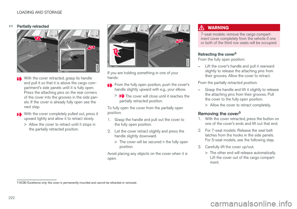
With the cover retracted, grasp its handle and pull it so that it is above the cargo com-partment's side panels until it is fully open.Press the attaching pins on the rear cornersof the cover into the grooves in the side pan-els. If the cover is already fully open see thenext step.
With the cover completely pulled out, press it upward lightly and allow it to retract slowly.
> Allow the cover to retract until it stops inthe partially retracted position.
If you are holding something in one of your hands:
From the fully open position, push the cover's handle slightly upward with e.g., your elbow. >
The cover will close until it reaches the
partially retracted position.
To fully open the cover from the partially open position:
1. Grasp the handle and pull out the cover to the fully open position.
2. Let the cover retract slightly and press the handle slightly downward.
> The cover will be secured n the fully openposition.
Avoid placing any objects on the cover when it is open.
WARNING
7-seat models: remove the cargo compart- ment cover completely from the vehicle if oneor both of the third row seats will be occupied.
Retracting the cover 5
From the fully open position:
–Lift the cover's handle and pull it rearward slightly to release the attaching pins fromtheir grooves. Allow the cover to retract.
From the partially retracted position:
–Grasp the handle and lift it slightly to release the attaching pins from their grooves. Pullthe cover to the fully open position.
> Allow the cover to retract completely.
Removing the cover 51. With the cover retracted, press the button on
one of the cover's ends and lift out that end.
2. For 7-seat models: Release the seat belt latches from the hooks in the side panels. For 5-seat models, see the following step.
3. Carefully lift the cover up/out. > The other end will release automatically.Lift the cover out of the cargo compart-ment.
5XC90 Excellence only: the cover is permanently mounted and cannot be retracted or removed.
Page 232 of 546
LOCKS AND ALARM
* Option/accessory, for more information, see Introduction.
230
Antenna locations for the start and lock system
The vehicle is equipped with a keyless 2
start and
lock system that requires a number of antennas located at various points in the vehicle.
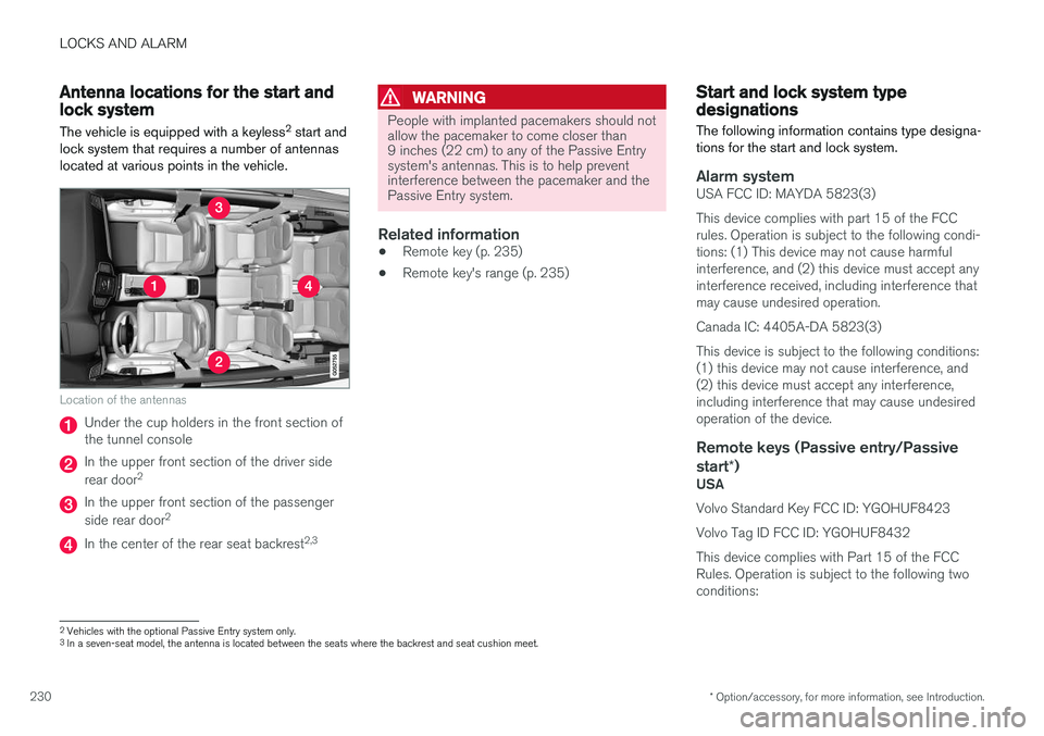
Location of the antennas
Under the cup holders in the front section of the tunnel console
In the upper front section of the driver side rear door 2
In the upper front section of the passenger side rear door 2
In the center of the rear seat backrest 2,3
WARNING
People with implanted pacemakers should not allow the pacemaker to come closer than9 inches (22 cm) to any of the Passive Entrysystem's antennas. This is to help preventinterference between the pacemaker and thePassive Entry system.
Related information
•
Remote key (p. 235)
• Remote key's range (p. 235)
Start and lock system type designations
The following information contains type designa- tions for the start and lock system.
Alarm systemUSA FCC ID: MAYDA 5823(3) This device complies with part 15 of the FCC rules. Operation is subject to the following condi-tions: (1) This device may not cause harmfulinterference, and (2) this device must accept anyinterference received, including interference thatmay cause undesired operation. Canada IC: 4405A-DA 5823(3)This device is subject to the following conditions: (1) this device may not cause interference, and(2) this device must accept any interference,including interference that may cause undesiredoperation of the device.
Remote keys (Passive entry/Passive start *)
USA Volvo Standard Key FCC ID: YGOHUF8423 Volvo Tag ID FCC ID: YGOHUF8432This device complies with Part 15 of the FCC Rules. Operation is subject to the following twoconditions:
2
Vehicles with the optional Passive Entry system only.
3 In a seven-seat model, the antenna is located between the seats where the backrest and seat cushion meet.
Page 291 of 546
DRIVER SUPPORT
}}}}
289
When City Safety applies the brakes, the brake lights will illuminate. When City Safety is triggered and applies the brakes, a text message will be displayed in theinstrument panel.
Related information
•
City Safety
™ troubleshooting (p. 295)
• City Safety in crossing traffic (p. 291)
• City Safety limitations (p. 293)
• City Safety symbols and messages (p. 297)
• Detecting cyclists and pedestrians with City Safety (p. 290)
• Rear Collision Warning (RCW) (p. 292)
• City Safety warning level settings (p. 289)
• City Safety in crossing traffic (p. 291)
• Seat belts (p. 64)
City Safety warning level settings
City Safety is always activated but the function's warning distance can be adjusted.
NOTE
City Safety cannot be turned off and activates automatically each time the engine/electricmotor is started.
Setting a warning level (distance)
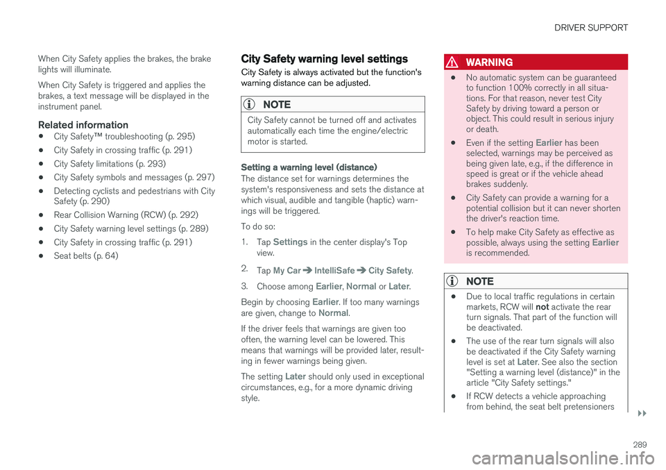
The distance set for warnings determines the system's responsiveness and sets the distance atwhich visual, audible and tangible (haptic) warn-ings will be triggered. To do so:1. Tap
Settings in the center display's Top
view.
2. Tap
My CarIntelliSafeCity Safety.
3. Choose among
Earlier, Normal or Later.
Begin by choosing
Earlier. If too many warnings
are given, change to Normal.
If the driver feels that warnings are given too often, the warning level can be lowered. Thismeans that warnings will be provided later, result-ing in fewer warnings being given. The setting
Later should only used in exceptional
circumstances, e.g., for a more dynamic driving style.
WARNING
• No automatic system can be guaranteed to function 100% correctly in all situa-tions. For that reason, never test CitySafety by driving toward a person orobject. This could result in serious injuryor death.
• Even if the setting
Earlier has been
selected, warnings may be perceived as being given late, e.g., if the difference inspeed is great or if the vehicle aheadbrakes suddenly.
• City Safety can provide a warning for apotential collision but it can never shortenthe driver's reaction time.
• To help make City Safety as effective as possible, always using the setting
Earlieris recommended.
NOTE
•Due to local traffic regulations in certain markets, RCW will
not activate the rear
turn signals. That part of the function will be deactivated.
• The use of the rear turn signals will alsobe deactivated if the City Safety warning level is set at
Later. See also the section
"Setting a warning level (distance)" in the article "City Safety settings."
• If RCW detects a vehicle approachingfrom behind, the seat belt pretensioners
Page 294 of 546
||
DRIVER SUPPORT
292
WARNING
•City Safety is a supplementary driving aid and does not function in all driving situa-tions or in all traffic, weather or road con-ditions.
• Warnings and braking for an approachingvehicle will usually come at a very latestage.
• The driver is responsible for maintaining asafe distance and speed. Never wait for awarning or for City Safety to take action.
LimitationsIn certain situations, it may be very difficult for City Safety to help the driver avoid a collision withan approaching vehicle in crossing traffic, forexample:
• on slippery roads when Electronic Stability Control is active
• if the approaching vehicle is detected at alate stage
• If the approaching vehicle is partiallyobscured by another vehicle
• if the approaching vehicle moves erratically(e.g., sudden lane changes at a late stage)
Related information
•
City Safety
™ (p. 287)
• City Safety limitations (p. 293)
Rear Collision Warning (RCW)
The
Rear Collision Warning with braking at
standstill (RCW) function can help the driver
avoid rear-end collisions.
RCW is activated automatically each time the engine is started and cannot be turned off. RCW can warn the driver of a vehicle approach- ing yours from behind by rapidly flashing yourrear turn signals. RCW is only activated when a vehicle is rapidly approaching your vehicle from behind. At speeds below 20 mph (30 km/h), if RCW determines that your vehicle is at risk of a rear-end collision, the front seat belt pretensionersand the Whiplash Protection System are acti-vated. Just prior to the collision, the brakes are also applied to help reduce your vehicle's forwardmovement if and when the collision occurs. How-ever, this can only happen if your vehicle is sta-tionary. The brakes will be released immediately if the accelerator pedal is pressed.
NOTE
• Due to local traffic regulations in certain markets, RCW will
not activate the rear
turn signals. That part of the function will be deactivated.
• The use of the rear turn signals will alsobe deactivated if the City Safety warning level is set at
Later. See also the section
"Setting a warning level (distance)" in the article "City Safety settings."
• If RCW detects a vehicle approachingfrom behind, the seat belt pretensionersand Whiplash Protection System will beactivated.
LimitationsIn some circumstances, it may be difficult for RCW to help the driver if there is a risk of a colli-sion, such as: •
In slippery conditions when Electronic Stability Control is active
• If the vehicle approaching from the rear isdetected at a late stage
• If the vehicle approaching from the rearchanges lanes at a late stage
• If the vehicle approaching from the rear ismoving at a speed above approx. 50 mph(80 km/h)
Page 354 of 546
STARTING AND DRIVING
352
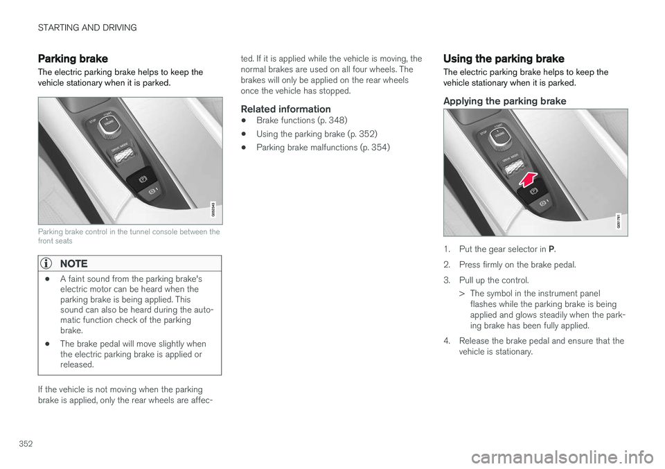
Parking brake The electric parking brake helps to keep the vehicle stationary when it is parked.
Parking brake control in the tunnel console between the front seats
NOTE
•A faint sound from the parking brake's electric motor can be heard when theparking brake is being applied. Thissound can also be heard during the auto-matic function check of the parkingbrake.
• The brake pedal will move slightly whenthe electric parking brake is applied orreleased.
If the vehicle is not moving when the parking brake is applied, only the rear wheels are affec- ted. If it is applied while the vehicle is moving, thenormal brakes are used on all four wheels. Thebrakes will only be applied on the rear wheelsonce the vehicle has stopped.
Related information
•
Brake functions (p. 348)
• Using the parking brake (p. 352)
• Parking brake malfunctions (p. 354)
Using the parking brake
The electric parking brake helps to keep the vehicle stationary when it is parked.
Applying the parking brake
1. Put the gear selector in P.
2. Press firmly on the brake pedal.
3. Pull up the control. > The symbol in the instrument panelflashes while the parking brake is being applied and glows steadily when the park-ing brake has been fully applied.
4. Release the brake pedal and ensure that the vehicle is stationary.
Page 358 of 546
||
STARTING AND DRIVING
356
Preconditioning
•If possible, precondition the vehicle with the charging cable before driving.
• Avoid parking the vehicle so that the passen-ger compartment becomes too hot or cold.Park, if possible, in a climate controlled park-ing garage.
• For short drives after using the precondition-ing function, turn off the climate systemblower if possible.
• If preconditioning is not possible in coldweather, use the seat and steering wheelheating primarily. Avoid heating the entirepassenger compartment, which reduces thehybrid battery's charge level.
Driving
•
Choose the Pure drive mode to help mini-
mize electric power consumption.
• Maintain a constant speed and an adequate distance to the vehicle ahead to minimizeuse of the brakes.
• Brake as gently as possible; doing socharges the hybrid battery using the inte-grated regenerative braking function.
• Balance energy requirements using theaccelerator pedal and utilize the gauge onthe instrument panel to see the amount ofpower available from the electric motor. Thishelps avoid starting the gasoline engineunnecessarily. The electric motor is moreenergy-efficient than the gasoline engine,especially at lower speeds. •
In hilly terrain, put the gear selector in mode B
to utilize the electric motor's braking func-
tion when the accelerator pedal is released. This helps charge the hybrid battery.
• Higher speeds increase energy consumptionand the vehicle's wind resistance increasesalong with speed. Do not exceed postedspeed limits.
• Select the
Save drive mode for higher
speeds when driving farther than is possible using the electric motor only.
• Avoid carrying unnecessary items (extra load)in the vehicle.
• Maintain correct tire pressure. Check tirepressure regularly (when the tires are cold).
• Remove snow tires when threat of snow orice has ended.
• Note that roof racks, ski racks, etc, increaseair resistance and also energy consumption.
• Avoid driving with open windows.
Handling and roadholding
•
Vehicle load, tire design and inflation pres-sure all affect vehicle handling. Therefore,check that the tires are inflated to the rec-ommended pressure according to the vehicleload. Loads should be distributed so thatcapacity weight or maximum permissible axleloads are not exceeded.
• At the specified curb weight your vehicle hasa tendency to understeer, which means thatthe steering wheel has to be turned more than might seem appropriate for the curva-ture of a bend. This ensures good stabilityand reduces the risk of rear wheel skid.Remember that these properties can alterwith the vehicle load. The heavier the load inthe cargo compartment, the less the ten-dency to understeer.
Related information
•
Hybrid-related information in the instrumentpanel (p. 130)
• Parking climate (preconditioning) (p. 179)
Page 373 of 546
STARTING AND DRIVING
* Option/accessory, for more information, see Introduction.371
ModeFunctions available
0•The odometer, clock and tem- perature gauge are illuminated
• Power seats
* can be adjusted
• The power windows can be oper-ated
• The 12-volt socket in the cargocompartment can be used
• The center display is activatedand can be used
• The infotainment system can beused for a limited time
In this mode, certain functions can only be used for a limited time to helpminimize battery drain
I• The laminated panoramic roof
*,
power seats */windows,12-volt
sockets in the passenger com- partment, Bluetooth, navigation system *, climate system blower,
windshield wipers can be oper- ated
• The infotainment system will start(if it was started when the ignitionwas switched off)
Using electrical current will drain the start battery in this mode.
ModeFunctions available
II• The headlights illuminate
• Warning/indicator lights illumi- nate for 5 seconds
• A number of other functions willalso be activated. However, the heated seats
* and heated rear
window functions can only be activated when the engine is run-ning.
This mode should only be used for very short periods to help avoiddraining the battery.
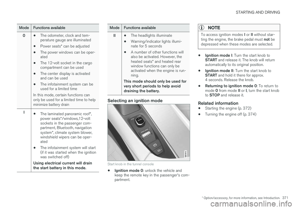
Selecting an ignition mode
Start knob in the tunnel console
• Ignition mode 0
: unlock the vehicle and
keep the remote key in the passenger's com- partment.
NOTE
To access ignition modes I or II without star-
ting the engine, the brake pedal must not be
depressed when these modes are selected.
• Ignition mode I
: Turn the start knob to
START and release it. The knob will return
automatically to its original position.
• Ignition mode II
: Turn the start knob to
START and hold it there for approx.
4 seconds. Release the knob.
• Returning to ignition mode 0
: To return to
mode 0 from mode II or I, turn the start knob
to STOP and release it.
Related information
•Starting the engine (p. 372)
• Turning the engine off (p. 374)
Page 450 of 546
WHEELS AND TIRES
448•
B-pillar
: The structural member at the side
of the vehicle behind the front door.
• Bead area of the tire
: Area of the tire next
to the rim.
• Sidewall of the tire
: Area between the bead
area and the tread.
• Tread area of the tire
: Area of the perime-
ter of the tire that contacts the road when mounted on the vehicle.
• Rim
: The metal support (wheel) for a tire or a
tire and tube assembly upon which the tirebeads are seated.
• Maximum load rating
: a figure indicating
the maximum load in pounds and kilogramsthat can be carried by the tire. This rating isestablished by the tire manufacturer.
• Maximum permissible inflation pressure
:
the greatest amount of air pressure thatshould ever be put in the tire. This limit is setby the tire manufacturer.
• Recommended tire inflation pressure
:
inflation pressure, established by Volvo,which is based on the type of tires that aremounted on a vehicle at the factory. Thisinformation can be found on the tire inflation placard(s) located on the driver's side B-pillarand in the tire inflation table in this chapter.
• Cold tires
: The tires are considered to be
cold when they have the same temperatureas the surrounding (ambient) air. This tem-perature is normally reached after the vehiclehas been parked for at least 3 hours.
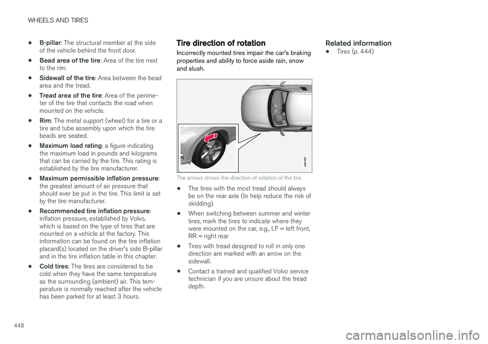
Tire direction of rotation
Incorrectly mounted tires impair the car's braking properties and ability to force aside rain, snowand slush.
The arrows shows the direction of rotation of the tire
• The tires with the most tread should always be on the rear axle (to help reduce the risk ofskidding).
• When switching between summer and wintertires, mark the tires to indicate where theywere mounted on the car, e.g., LF = left front,RR = right rear
• Tires with tread designed to roll in only onedirection are marked with an arrow on thesidewall.
• Contact a trained and qualified Volvo servicetechnician if you are unsure about the treaddepth.
Related information
•Tires (p. 444)