brake light VOLVO XC90 T8 2016 Owner´s Manual
[x] Cancel search | Manufacturer: VOLVO, Model Year: 2016, Model line: XC90 T8, Model: VOLVO XC90 T8 2016Pages: 546, PDF Size: 10.26 MB
Page 5 of 546
3
Starting or moving a vehicle in safety mode88
Airbag system 89
Driver/passenger side airbags 89
Inflatable curtains 92
Side impact airbags 93
INSTRUMENTS AND CONTROLS
Trip computer96
Displaying trip computer information 97
Displaying trip statistics 98
HomeLink ®
Wireless Control System *99
Programming the HomeLink ®
Wire-
less Control System * 100
Instruments and controls 103
Adjusting the power door mirrors 105
Laminated panoramic roof *
106
Operating the laminated panoramic roof *
107
Power windows 109
Operating the power windows 109
Rearview mirror 110
Using sun shades 111
Settings view 111
Categories in Settings view 112
Changing system settings in Set- tings view 114
Changing settings in apps 115
Resetting the settings view 115
Resetting user data when the vehiclechanges owners 116
Ambient temperature sensor 116
Clock 117
Head-up display (HUD) *
117
Voice control
120
Using voice commands 121
Voice control for cell phones 122
Voice control for radio and media 122
Climate system voice commands 123
Navigation system voice commands 124
Voice control settings 125
Indicator symbols in the instrument panel 125
Instrument panel 127
Instrument panel App menu 129
Hybrid-related information in the instrument panel 130
Instrument panel licenses 132
Warning symbols in the instrument panel 137
Compass 139
Calibrating the compass 139
Lighting panel and controls 140
Low beam headlights 142
Daytime Running Lights (DRL) 142
High and low beam headlights 143
Active Bending Lights *
145
Brake lights 146
Rear fog lights 146
Hazard warning flashers 147
Parking lights 147
Page 9 of 546
7
Electronic Stability Control (ESC) sport mode324
Electronic Stability Control (ESC)symbols and messages 325
Roll stability control (RSC) 327
Driver Alert Control (DAC) 327
Driver Alert Control limitations 328
Using Driver Alert Control (DAC) 328
Distance Alert *
329
Using Distance Alert *
329
Distance Alert * limitations
330
Blind Spot Information (BLIS) *
330
Blind Spot Information (BLIS) * On/Off
332
Blind Spot Information (BLIS) * limitations
332
Cross Traffic Alert (CTA) *
333
Activating/deactivating Cross Traffic Alert (CTA) * 334
Cross Traffic Alert (CTA) * limitations
335
Blind Spot Information (BLIS) * with
Cross Traffic Alert (CTA) * symbols
and messages 337
Driving lane assistance 338
Activating/deactivating Lane Departure Warning (LDW) 340
Activating/deactivating Lane Keeping Aid (LKA) * 340
Driving lane assistance symbols and messages
342
STARTING AND DRIVING
Starting and driving
346
Brakes 346
Brake functions 348
Auto-hold brake function 349
Brake assist system 349
Braking effect after a collision 350
Emergency brake lights 350
Hill Descent Control (HDC) 350
Hill Start Assist 351
Parking brake 352
Using the parking brake 352
Parking brake malfunctions 354
Before a long distance trip 355
Driving economically 355
Driving through standing water 357
Overheating the engine and transmission 357
Winter driving 358
Towing eyelet 359
Towing recommendations 360
Fuel 361
Octane rating 362
Opening/closing the fuel filler door 363
Emission controls 364
Jump starting 365
Page 20 of 546
||
INTRODUCTION
18
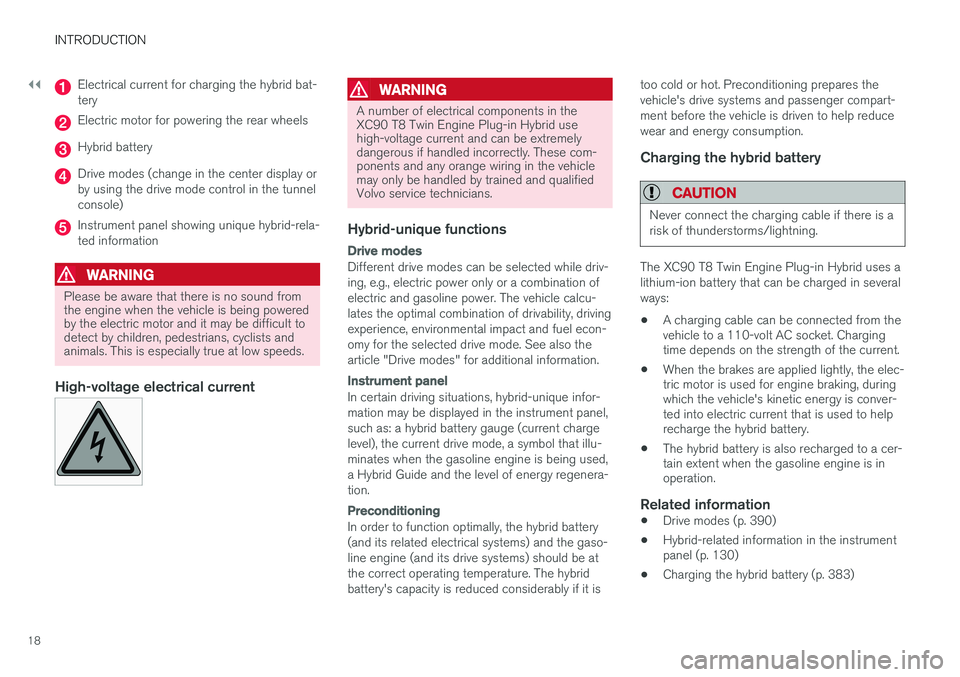
Electrical current for charging the hybrid bat- tery
Electric motor for powering the rear wheels
Hybrid battery
Drive modes (change in the center display or by using the drive mode control in the tunnelconsole)
Instrument panel showing unique hybrid-rela- ted information
WARNING
Please be aware that there is no sound from the engine when the vehicle is being poweredby the electric motor and it may be difficult todetect by children, pedestrians, cyclists andanimals. This is especially true at low speeds.
High-voltage electrical current
WARNING
A number of electrical components in the XC90 T8 Twin Engine Plug-in Hybrid usehigh-voltage current and can be extremelydangerous if handled incorrectly. These com-ponents and any orange wiring in the vehiclemay only be handled by trained and qualifiedVolvo service technicians.
Hybrid-unique functions
Drive modes
Different drive modes can be selected while driv- ing, e.g., electric power only or a combination ofelectric and gasoline power. The vehicle calcu-lates the optimal combination of drivability, drivingexperience, environmental impact and fuel econ-omy for the selected drive mode. See also thearticle "Drive modes" for additional information.
Instrument panel
In certain driving situations, hybrid-unique infor- mation may be displayed in the instrument panel,such as: a hybrid battery gauge (current chargelevel), the current drive mode, a symbol that illu-minates when the gasoline engine is being used,a Hybrid Guide and the level of energy regenera-tion.
Preconditioning
In order to function optimally, the hybrid battery (and its related electrical systems) and the gaso-line engine (and its drive systems) should be atthe correct operating temperature. The hybridbattery's capacity is reduced considerably if it istoo cold or hot. Preconditioning prepares thevehicle's drive systems and passenger compart-ment before the vehicle is driven to help reducewear and energy consumption.
Charging the hybrid battery
CAUTION
Never connect the charging cable if there is a risk of thunderstorms/lightning.
The XC90 T8 Twin Engine Plug-in Hybrid uses a lithium-ion battery that can be charged in severalways:
• A charging cable can be connected from the vehicle to a 110-volt AC socket. Chargingtime depends on the strength of the current.
• When the brakes are applied lightly, the elec-tric motor is used for engine braking, duringwhich the vehicle's kinetic energy is conver-ted into electric current that is used to helprecharge the hybrid battery.
• The hybrid battery is also recharged to a cer-tain extent when the gasoline engine is inoperation.
Related information
•Drive modes (p. 390)
• Hybrid-related information in the instrumentpanel (p. 130)
• Charging the hybrid battery (p. 383)
Page 22 of 546
INTRODUCTION
20
Volvo and the environment Volvo is committed to the well-being of its cus- tomers. As a natural part of this commitment, wecare about the environment in which we all live.Concern for the environment means an everydayinvolvement in reducing our environmentalimpact.
Volvo's environmental activities are based on a holistic view, which means we consider the over-all environmental impact of a product throughoutits complete life cycle. In this context, design, pro-duction, product use, and recycling are all impor-tant considerations. In production, Volvo haspartly or completely phased out several chemicalsincluding CFCs, lead chromates, asbestos, andcadmium; and reduced the number of chemicalsused in our plants 50% since 1991. Volvo was the first in the world to introduce into production a three-way catalytic converter with aLambda sond, now called the heated oxygen sen-sor, in 1976. The current version of this highlyefficient system reduces emissions of harmfulsubstances (CO, HC, NOx) from the exhaust pipeby approximately 95 – 99% and the search toeliminate the remaining emissions continues.Volvo is the only automobile manufacturer tooffer CFC-free retrofit kits for the air conditioningsystem of all models as far back as the 1975model 240. Advanced electronic engine controlsand cleaner fuels are bringing us closer to ourgoal. In addition to continuous environmentalrefinement of conventional gasoline-poweredinternal combustion engines, Volvo is activelylooking at advanced technology alternative-fuelvehicles. When you drive a Volvo, you become our partner in the work to lessen the car's impact on theenvironment. To reduce your vehicle's environ-mental impact, you can:
• Maintain proper air pressure in your tires. Tests have shown decreased fuel economywith improperly inflated tires.
• Follow the recommended maintenanceschedule in your Warranty and ServiceRecords Information booklet.
• Drive at a constant speed whenever possible.
• See a trained and qualified Volvo servicetechnician as soon as possible for inspectionif the check engine (malfunction indicator)light illuminates, or stays on after the vehiclehas started.
• Properly dispose of any vehicle-related wastesuch as used motor oil, used batteries, brakepads, etc.
• When cleaning your vehicle, please use gen-uine Volvo car care products. All Volvo carcare products are formulated to be environ-mentally friendly.
Volvo XC90 T8 Twin Engine Plug-in Hybrid
• If possible, precondition the vehicle with the charging cable before driving.
• If preconditioning is not possible in coldweather, use the seat and steering wheelheating primarily. Avoid heating the entirepassenger compartment, which reduces thehybrid battery's charge level.
• Choose the
Pure drive mode to help mini-
mize electric power consumption.
• In hilly terrain, put the gear selector in mode B
to utilize the electric motor's braking func-
tion when the accelerator pedal is released. This helps charge the hybrid battery.
• Select the
Save drive mode for higher
speeds when driving farther than is possible using the electric motor only.
Related information
• Driving economically (p. 355)
Page 23 of 546
INTRODUCTION
* Option/accessory, for more information, see Introduction.21
Owner's manual and the environment
The wood pulp in Volvo's printed owner's infor- mation comes from FSC ®
(Forest Stewardship
Council ®
) certified forests and other responsible
sources.
FSC ®
The symbol above indicates that the wood pulp is FSC
®
certified.
Related information
• Volvo and the environment (p. 20)
IntelliSafe
—driver support
IntelliSafe is Volvo's philosophy regarding vehi- cle safety. It encompasses a number of systems,both standard and optional, that are designed tohelp make driving and traveling in a Volvo safer.
SupportSystems that help make driving safer are an inte- gral part of IntelliSafe. These include optional features such as Adaptive Cruise Control * that
helps maintain a set distance to a vehicle ahead,Park Assist Pilot *, which assists in parking the
vehicle, Cross Traffic Alert *, Blind Spot
Information *, etc.
Accident preventionSystems such as City Safety are designed to automatically apply the brakes in situations inwhich the driver does not have time to react. Lane Keeping Aid * alerts the drive if the vehicle
inadvertently crosses a lane's/road's side marker line.
ProtectionThe vehicle is equipped with e.g., seat belt pre-tensioners that pull the seat belts taut in criticalsituations when there is a collision risk andnumerous airbags designed to help provide cush-ioning if certain types of collisions should occur.
Related information
• Adaptive Cruise Control (ACC)
* (p. 266)
• Park Assist Pilot (PAP)
* (p. 316) •
High and low beam headlights (p. 143)
• Cross Traffic Alert (CTA)
* (p. 333)
• Blind Spot Information (BLIS)
* (p. 330)
• City Safety
™ (p. 287)
• Driving lane assistance (p. 338)
• Airbag system (p. 89)
• Roll stability control (RSC) (p. 327)
• Seat belts (p. 64)
• General safety information (p. 60)
Page 106 of 546
||
INSTRUMENTS AND CONTROLS
* Option/accessory, for more information, see Introduction.
104
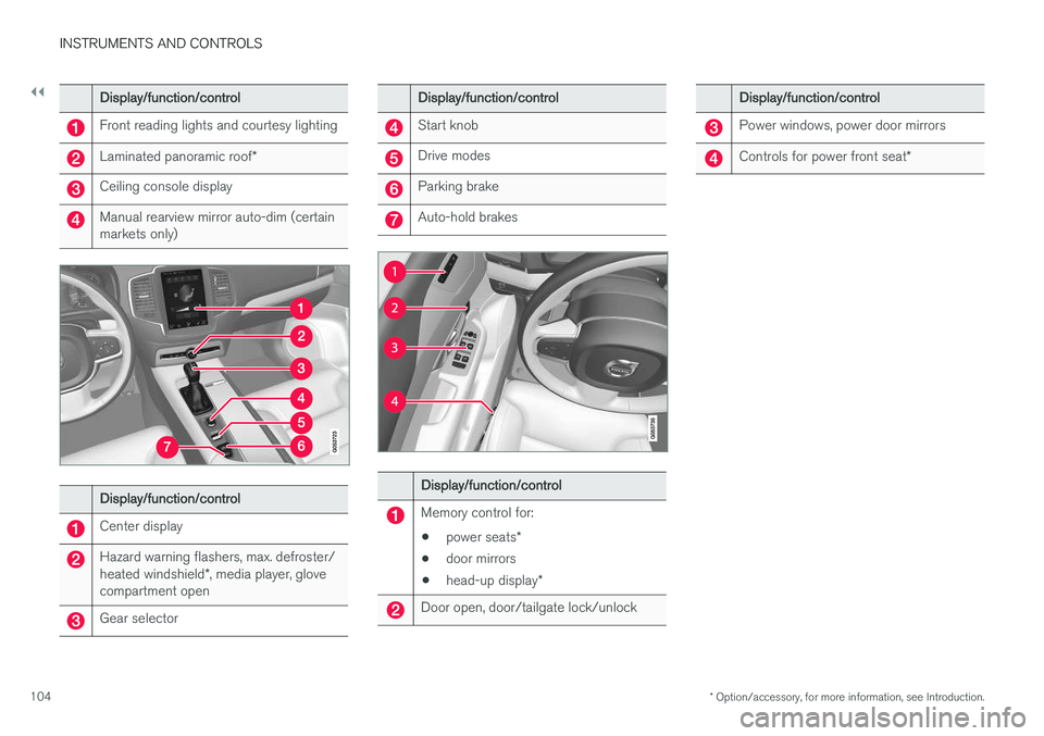
Display/function/control
Front reading lights and courtesy lighting
Laminated panoramic roof *
Ceiling console display
Manual rearview mirror auto-dim (certain markets only)
Display/function/control
Center display
Hazard warning flashers, max. defroster/ heated windshield*, media player, glove
compartment open
Gear selector
Display/function/control
Start knob
Drive modes
Parking brake
Auto-hold brakes
Display/function/control
Memory control for:
• power seats
*
• door mirrors
• head-up display
*
Door open, door/tailgate lock/unlock
Display/function/control
Power windows, power door mirrors
Controls for power front seat *
Page 127 of 546
INSTRUMENTS AND CONTROLS
}}
125
Voice control settings
There are a number of settings that can be made for the voice control system.
Open the center display's Top view and tap
SettingsSystemVoice Control and
select settings. •
Repeat Mode
•Gender
•Speech Rate
Sound settings
Open Top view and tap SettingsSound
System VolumesVoice Control.
Changing languages
The voice control system only understands the languages marked by the
symbol in the list
of possible system languages. Changing the language for this system also affects menus, messages and help texts. Open Top view and tap
SettingsSystemLanguage.
Related information
• Voice control (p. 120)
• Using voice commands (p. 121)
• Navigation system voice commands (p. 124)
Indicator symbols in the instrument panel
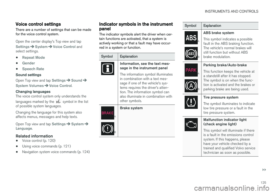
The indicator symbols alert the driver when cer- tain functions are activated, that a system isactively working or that a fault may have occur-red in a system or function.
SymbolExplanation
Information, see the text mes- sage in the instrument panel The information symbol illuminates in combination with a text mes-sage if one of the vehicle's sys-tems requires the driver's atten-tion. The information symbol canalso illuminate in combination withother symbols.
A
B
Brake system
SymbolExplanation
A
B
ABS brake system This symbol indicates a possible fault in the ABS braking function.The vehicle's normal brakes willstill function but without ABSbrake modulation.
A
B
Parking brake/Auto-brake This function keeps the vehicle at a standstill after it has stopped.The symbol is on when the func-tion is activated and the brakes orparking brake are being used.
Tire pressure system The symbol illuminates to indicate low tire pressure or a fault in thetire pressure system.
Malfunction indicator light (check engine light) This symbol will illuminate if there is a fault in the emissions controlsystem. If this happens, pleasehave your vehicle checked by atrained and qualified Volvo servicetechnician as soon as possible.
Page 139 of 546
INSTRUMENTS AND CONTROLS
}}
137
CLAIM, DAMAGES OR OTHER LIABILITY, WHETHER IN AN ACTION OF CONTRACT,TORT OR OTHERWISE, ARISING FROM, OUTOF OR IN CONNECTION WITH THE SOFTWAREOR THE USE OR OTHER DEALINGS IN THESOFTWARE. Except as contained in this notice, the name of Silicon Graphics, Inc. shall not be used inadvertising or otherwise to promote the sale, useor other dealings in this Software without priorwritten authorization from Silicon Graphics, Inc.
Related information
•
Instrument panel (p. 127)
Warning symbols in the instrument panel
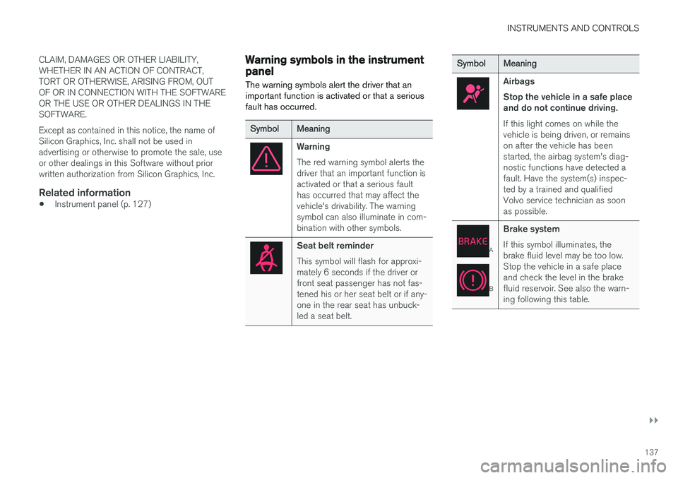
The warning symbols alert the driver that an important function is activated or that a seriousfault has occurred.
SymbolMeaning
Warning The red warning symbol alerts the driver that an important function isactivated or that a serious faulthas occurred that may affect thevehicle's drivability. The warningsymbol can also illuminate in com-bination with other symbols.
Seat belt reminder This symbol will flash for approxi- mately 6 seconds if the driver orfront seat passenger has not fas-tened his or her seat belt or if any-one in the rear seat has unbuck-led a seat belt.
SymbolMeaning
Airbags Stop the vehicle in a safe place and do not continue driving. If this light comes on while the vehicle is being driven, or remainson after the vehicle has beenstarted, the airbag system's diag-nostic functions have detected afault. Have the system(s) inspec-ted by a trained and qualifiedVolvo service technician as soonas possible.
A
B
Brake system If this symbol illuminates, the brake fluid level may be too low.Stop the vehicle in a safe placeand check the level in the brakefluid reservoir. See also the warn-ing following this table.
Page 148 of 546
INSTRUMENTS AND CONTROLS
* Option/accessory, for more information, see Introduction.
146
Brake lights The brake lights illuminate automatically when the brakes are applied.
In addition to illuminating when the brake pedal is depressed, the brake lights also illuminate whenone of the driver support systems (e.g., adaptivecruise control, City Safety or collision warning)slow the vehicle.
Related information
• Adaptive Cruise Control (ACC)
* (p. 266)
• City Safety
™ (p. 287)
• Emergency brake lights (p. 350)
Rear fog lights
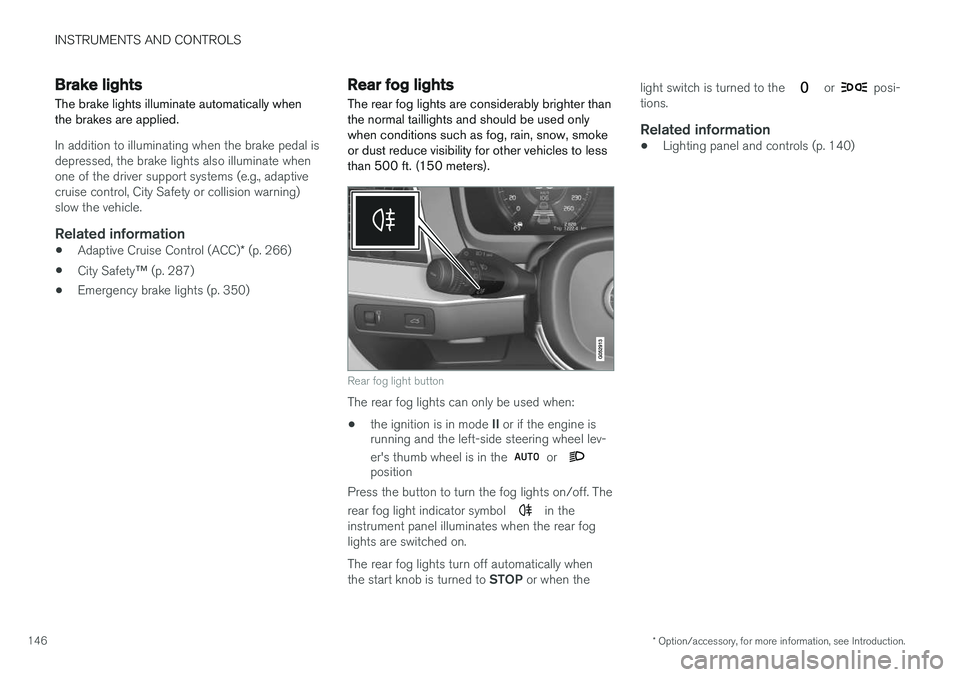
The rear fog lights are considerably brighter than the normal taillights and should be used onlywhen conditions such as fog, rain, snow, smokeor dust reduce visibility for other vehicles to lessthan 500 ft. (150 meters).
Rear fog light button
The rear fog lights can only be used when:
• the ignition is in mode
II or if the engine is
running and the left-side steering wheel lev- er's thumb wheel is in the
or position
Press the button to turn the fog lights on/off. The rear fog light indicator symbol
in the
instrument panel illuminates when the rear fog lights are switched on. The rear fog lights turn off automatically when the start knob is turned to STOP or when the light switch is turned to the
or posi-
tions.
Related information
• Lighting panel and controls (p. 140)
Page 167 of 546
INSTRUMENTS AND CONTROLS
}}
* Option/accessory, for more information, see Introduction.165
2.
Press and release the M button. The indica-
tor light in the button will illuminate.
3. Press button 1, 2 or 3 within 3 seconds to
store the current position of the seat/ mirrors/head-up display in the selected but-ton.
> When the position has been stored in the selected button, an audible signal will sound and the indicator light in the M but-
ton will go out.
If none of the buttons (1, 2 or 3) is pressedwithin 3 seconds, the indicator light in the M but-
ton will go out and the position will not be stored.
The seat/mirrors/head-up display must be moved before a new position can be stored.
Using a stored positionA stored position can be used when one of thefront doors is opened or closed:
Front door open
–Press one of the bottons ( 1–3 ) briefly. The
seat, door mirrors and head-up display will move to the positions stored in that button.
Front door closed
–Press and hold one of the buttons ( 1–3 ) until
the seat, door mirrors and head-up display have moved to the positions stored in thatbutton. The seat, door mirrors and head-up display willstop automatically if the button is released beforethe they have reached the stored positions.
WARNING
•
Because the driver's seat can be adjusted with the ignition off, children should neverbe left unattended in the vehicle.
• Movement of the seat can be STOPPEDat any time by pressing any button on thepower seat control panel.
• Do not adjust the seat while driving. Theseat should be adjusted so that the brakepedal can be depressed fully. In addition,position the seat as far rearward as com-fort and control allow.
• The seat rails on the floor must not beobstructed in any way when the seat is inmotion.
Related information
•
Adjusting power front seats
* (p. 163)
• Power front seats
* (p. 163)
Multifunctional front seats *
In addition to the adjustment settings offered by the power seat controls, the multifunction controlprovides additional possibilities for convenienceand comfort.
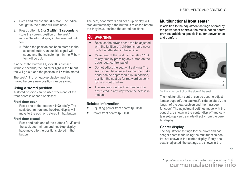
Multifunction control on the side of the seat
The multifunction control can be used to adjust lumbar support *, the backrest's side bolsters *, the
length of the seat cushion and the massagefunction *. The adjustment settings made with the
control are shown in the center display * and cer-
tain settings can be made directly from the cen- ter display.
Center displayThe adjustment settings for the driver and pas-senger seats made using the multifunction con-trol are shown in the center display. If only oneseat is adjusted, the settings are shown in the