engine VOLVO XC90 T8 2017 Owner´s Manual
[x] Cancel search | Manufacturer: VOLVO, Model Year: 2017, Model line: XC90 T8, Model: VOLVO XC90 T8 2017Pages: 580, PDF Size: 10.37 MB
Page 60 of 580
||
INTRODUCTION
* Option/accessory.
58
Using the search function
1.
Tap the magnifying glass icon () in the
owner's manual's upper menu. A keyboard will appear at the bottom of the screen.
2. Enter a word, e.g., "seat belt." > Suggested articles will be displayed asmore characters are entered.
3. Confirm by tapping the article. To leave search mode tap the up-arrow next to thesearch box.
Related information
• On-board digital owner's manual (p. 55)
• Using the center display keyboard (p. 36)
Glass
Laminated glass
The windshield and panoramic roof
* are made of
laminated glass, which is reinforced to help pre- vent break-ins and to provide additional sound-proofing. Laminated glass is optional for theother side windows.
Laminated glass symbol 5
Related information
•
Laminated panoramic roof
* (p. 108)
• Power windows (p. 111)
• Defrosting windows and mirrors (p. 204)
• Using sun curtains
* (p. 113)
• Rearview mirror (p. 112)
• Power windows (p. 111)
• Head-up display (HUD)
* (p. 120)
• Activating/deactivating the rain sensor (p. 161)
• Windshield and headlight washers (p. 162)
• Tailgate window wiper and washer (p. 163)
Technician certification
In addition to Volvo factory training, Volvo sup- ports certification by the National Institute forAutomotive Service Excellence (A.S.E.).
Certified technicians have demonstrated a high degree of competence in specific areas. Besidespassing exams, each technician must also haveworked in the field for two or more years before acertificate is issued. These professional techni-cians are best able to analyze vehicle problemsand perform the necessary maintenance proce-dures to keep your Volvo at peak operating con-dition.
Twin Engine Plug-in Hybrid vehicles
Technicians performing work on a vehicle with electrification should also have the necessarytraining and specialized certification required forperforming repairs and/or maintenance on avehicle with electrification.
WARNING
A number of electrical components in Twin Engine Plug-in Hybrid vehicles use high-volt-age current and can be extremely dangerousif handled incorrectly. These components andany orange wiring in the vehicle may only behandled by trained and qualified Volvo servicetechnicians.
5
This symbol is not shown on the windshield or panoramic roof.
Page 62 of 580
SAFETY
60
General safety information The vehicle is equipped with a number of safety systems for the driver and passengers.
In the event of an accident, there are a number of sensors in the vehicle that react and triggersafety systems such as Roll Stability Control, air-bags, seat belt pretensioners, etc., depending onthe severity of the collision. There are alsomechanical systems such as the WhiplashProtection System.
Warning symbol in the instrument panelThe warning symbol in the instrumentpanel illuminates when the ignition is in mode II or higher. It will go out after
approx. 6 seconds if no faults are
detected in the airbag system.
WARNING
• If the SRS warning light stays on after the engine has started or if it illuminateswhile you are driving, have the vehicleinspected by a trained and qualified Volvoservice technician as soon as possible.
• Never try to repair any component or partof the SRS yourself. Any interference inthe system could cause malfunction andserious injury. All work on these systemsshould be performed by a trained andqualified Volvo service technician. If the dedicated warning symbol is notfunctioning, the general warning sym-bol will illuminate instead and the samemessage will be displayed in the instru-
ment panel.
Related information
• Safety during pregnancy (p. 62)
• Seat belts (p. 64)
• Airbag system (p. 69)
• Safety mode (p. 78)
• Whiplash protection system (p. 63)
• Child safety (p. 79)
Occupant safety Safety is Volvo's cornerstone.
Volvo's concern for safetyOur concern for safety dates back to 1927 when the first Volvo rolled off the production line.Three-point seat belts (a Volvo invention), safetycages, and energy-absorbing impact zones weredesigned into Volvo vehicles long before it wasfashionable or required by government regulation. We will not compromise our commitment to safety. We continue to seek out new safety fea-tures and to refine those already in our vehicles.You can help. We would appreciate hearing yoursuggestions about improving automobile safety.We also want to know if you ever have a safetyconcern with your vehicle. Call us in the U.S. at:1-800-458-1552 or in Canada at:1-800-663-8255.
Page 71 of 580
SAFETY
69
Rear seats
The rear seat belt reminder has two functions.• It indicates which seat belts are buckled in the rear seats. This will also be displayed inan instrument panel graphic.
• It also provides audio and visual reminders ifa rear seat belt is unbuckled while the vehi-cle is in motion. The reminders will disappearwhen the seat belt has been buckled again or can be erased by pressing the
O button
on the steering wheel keypad.
Door/hood/tailgate/fuel filler door
reminder
If a door, the hood, tailgate or fuel filler door is/are not properly closed, this will be indicated ina graphic in the instrument panel. Stop the vehi-cle safely and close the source of the reminder.
If the vehicle is moving at a speedunder approx.6 mph (10 km/h), theinformation symbol will illuminate in theinstrument panel.
At speeds above approx. 6 mph (10 km/h), the warning symbol will illu-minate in the instrument panel.
Related information
•Seat belts (p. 64)
• Buckling and unbuckling seat belts (p. 66)
• Seat belt pretensioners (p. 65)
Airbag system As an enhancement to the three-point seat belts, your vehicle is equipped with an airbag system.
WARNING
•
If the airbag warning light stays on after the engine has started or if it illuminateswhile you are driving, have the vehicleinspected by a trained and qualified Volvoservice technician as soon as possible.
• Never try to repair any component or partof the airbag systems yourself. Any inter-ference in the system could cause mal-function and serious injury. All work onthese systems should be performed by atrained and qualified Volvo service techni-cian.
WARNING
If your vehicle has become flood-damaged in any way (e.g., soaked carpeting/standingwater on the floor of the vehicle), do notattempt to start the vehicle. This may causeairbag deployment which could result in seri-ous injury. Have the vehicle towed to a trainedand qualified Volvo service technician forrepairs. Before attempting to tow the vehicle:
1. Switch off the ignition for at least
10 minutes and disconnect the battery.
2. Follow the instructions for manually over- riding the shiftlock system.
Deployed airbags
WARNING
If any of the airbags have deployed:
• Do not attempt to drive the vehicle. Have it towed to a qualified repair facility.
• If necessary seek medical attentIon.
Page 80 of 580
SAFETY
78
Safety mode As a safety precaution after a collision, the func- tionality of some of the vehicle's systems may bereduced.
If the vehicle has been involved in a collision, the text Safety mode may appear in the information
display.
NOTE
This text can only be shown if the display is undamaged and the vehicle's electrical sys-tem is intact.
Safety mode is a feature that is triggered if one or more of the safety systems such as the front/side airbags inflatable curtain, etc., or one ormore of the seat belt pretensioners has deployed.The collision may have damaged an importantfunction in the vehicle, such as the fuel lines,sensors for one of the safety systems, the brakesystem, etc.
WARNING
• Never attempt to repair the vehicle your- self or to reset the electrical system after the vehicle has displayed
Safety mode.
This could result in injury or improper sys- tem function.
• Restoring the vehicle to normal operatingstatus should only be done by a trainedand qualified Volvo service technician.
• After
Safety mode has been displayed, if
you detect the odor of fuel vapor, or see any signs of fuel leakage, do not attemptto start the vehicle. Leave the vehicleimmediately.
Related information
• Starting or moving a vehicle in safety mode(p. 78)
• General safety information (p. 60)
Starting or moving a vehicle in safety mode
If
Safety mode has been set, it may be possible
to start and move the vehicle, for example, if it is blocking traffic.
Starting the vehicle in safety mode1. Check the vehicle for damage, particularly for fuel leakage or the smell of gasoline fumes. If the damage to the vehicle is minor and there is no fuel leakage/fumes, you mayattempt to start the engine and move thevehicle.
WARNING
If you smell gasoline fumes or detect fuel leakage while Safety mode See Owner's
manual is displayed in the instrument panel,
do not attempt to start the vehicle . Leave
the vehicle immediately.
2. Turn the start knob to STOP and release it.
3. Try to start the vehicle. >
Vehicle start System check, wait will
be displayed in the instrument panel while the vehicle's electrical system attempts toreset to normal mode. This may take up toa minute.
Page 123 of 580
INSTRUMENTS AND CONTROLS
}}
121
NOTE
The driver's ability to see information in the HUD may be impeded by: •the use of polarizing sunglasses
• the use of an aftermarket or non-Volvo replacement windshield
• not sitting in the center of the driver'sseat
• objects on the HUD projector glass onthe dashboard
• certain ambient lighting conditions
• certain types of vision problems, whichmay also result in headaches or eyestrain.
• Activating/deactivating and settings forHUD are only possible when an image isprojected on the windshield. The enginemust be running.
Activating/deactivating HUDHUD can be activated in two ways in the center display:
Via Function view
Tap the Head-up display but-
ton.
Via settings
1. Tap Settings in Top view.
2. Tap
My CarDisplays.
3. Select/deselect
Head-Up Display.
This selection can be stored as a personal set- ting in a driver profile.
Selecting display alternatives1. Tap Settings in Top view.
2. Tap
My CarDisplaysHead-Up
Display Options.
Tap Go to the center display's Settings view and select
Driver Display & Head-up
Display.
3. Select :
Show Navigation, Show Road
Sign Information, Show Driver Supportor Show Phone.
This selection can be stored as a personal set- ting in a driver profile.
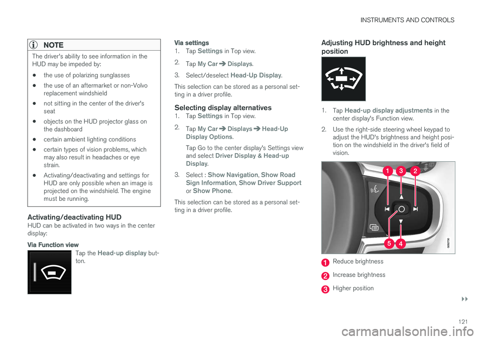
Adjusting HUD brightness and height position
1. Tap Head-up display adjustments in the
center display's Function view.
2. Use the right-side steering wheel keypad to adjust the HUD's brightness and height posi- tion on the windshield in the driver's field ofvision.
Reduce brightness
Increase brightness
Higher position
Page 133 of 580
INSTRUMENTS AND CONTROLS
}}
131
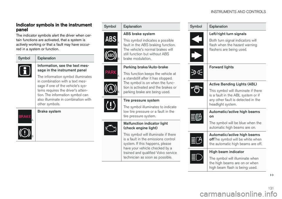
Indicator symbols in the instrument panelThe indicator symbols alert the driver when cer- tain functions are activated, that a system isactively working or that a fault may have occur-red in a system or function.
Symbol Explanation
Information, see the text mes- sage in the instrument panel The information symbol illuminates in combination with a text mes-sage if one of the vehicle's sys-tems requires the driver's atten-tion. The information symbol canalso illuminate in combination withother symbols.
A
BBrake system
Symbol
Explanation
A
BABS brake system This symbol indicates a possible fault in the ABS braking function.The vehicle's normal brakes willstill function but without ABSbrake modulation.
A
B
Parking brake/Auto-brake This function keeps the vehicle at a standstill after it has stopped.The symbol is on when the func-tion is activated and the brakes orparking brake are being used.
Tire pressure system The symbol illuminates to indicate low tire pressure or a fault in thetire pressure system.
Malfunction indicator light (check engine light) This symbol will illuminate if there is a fault in the emissions controlsystem. If this happens, pleasehave your vehicle checked by atrained and qualified Volvo servicetechnician as soon as possible.
Symbol
Explanation
Left/right turn signals Both turn signal indicators will flash when the hazard warningflashers are being used.
Forward lights
Active Bending Lights (ABL) This symbol will illuminate if there is a fault in the ABL system or ifany other fault is detected in theheadlight system.
Automatic/active high beams on The symbol will be blue when the automatic high beams are on.
Automatic/active high beams offThe symbol will be white when
the automatic high beams are off.
High beam indicator The symbol will illuminate when the high beams are on or whenhigh beam flash is being used.
Page 134 of 580
||
INSTRUMENTS AND CONTROLS
132
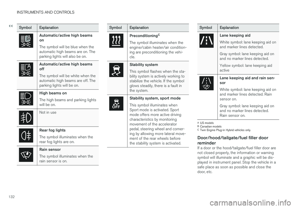
SymbolExplanation
Automatic/active high beams on The symbol will be blue when the automatic high beams are on. Theparking lights will also be on.
Automatic/active high beams off The symbol will be white when the automatic high beams are off. Theparking lights will be on.
High beams on The high beams and parking lights will be on.
Not in use
Rear fog lights The symbol illuminates when the rear fog lights are on.
Rain sensor The symbol illuminates when the rain sensor is on.
SymbolExplanation
Preconditioning C
The symbol illuminates when the engine/cabin heater/air condition-ing are preconditioning the vehi-cle.
Stability system This symbol flashes when the sta- bility system is actively working tostabilize the vehicle. If the symbolglows steadily, there is a fault inthe system.
Stability system, sport mode This symbol illuminates when Sport mode is activated. Sportmode offers more active drivingcharacteristics by monitoringmovement of the acceleratorpedal, steering wheel and corner-ing by allowing more lateral move-ment of the rear wheels beforethe stability system is activated.
Symbol Explanation
Lane keeping aid White symbol: lane keeping aid on and marker lines detected. Gray symbol: lane keeping aid on and no marker lines detected. Yellow symbol: lane keeping aid active
Lane keeping aid and rain sen- sor White symbol: lane keeping aid on and marker lines detected. Rainsensor on. Gray symbol: lane keeping aid on and no marker lines detected.Rain sensor on.
A
US models
B Canadian models
C Twin Engine Plug-in Hybrid vehicles only.
Door/hood/tailgate/fuel filler door
reminder
If a door or the hood/tailgate/fuel filler door are not closed properly, the information or warningsymbol will illuminate and a graphic will be dis-played in instrument panel. Stop the vehicle in asafe place as soon as possible and close thedoor, etc.
Page 135 of 580
INSTRUMENTS AND CONTROLS
}}
133
Related information
•Instrument panel (p. 128)
• Warning symbols in the instrument panel (p. 140)
• Door and seat belt reminders (p. 68)
Hybrid-related information in the instrument panel
Different types of information will be displayed in the instrument panel, depending on the drivemode selected. These drive modes offer uniqueways of helping the driver achieve the best pos-sible driving economy. The vehicle also stores driving statistics that can be viewed in the form of a bar graph.
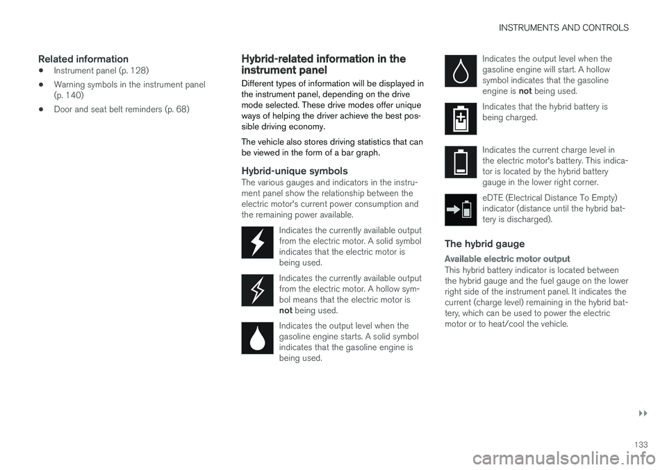
Hybrid-unique symbolsThe various gauges and indicators in the instru- ment panel show the relationship between theelectric motor's current power consumption andthe remaining power available.
Indicates the currently available outputfrom the electric motor. A solid symbolindicates that the electric motor isbeing used.
Indicates the currently available output from the electric motor. A hollow sym-bol means that the electric motor is not being used.
Indicates the output level when the gasoline engine starts. A solid symbolindicates that the gasoline engine isbeing used.
Indicates the output level when the gasoline engine will start. A hollowsymbol indicates that the gasoline engine is not being used.
Indicates that the hybrid battery is being charged.
Indicates the current charge level in the electric motor's battery. This indica-tor is located by the hybrid batterygauge in the lower right corner.
eDTE (Electrical Distance To Empty) indicator (distance until the hybrid bat-tery is discharged).
The hybrid gauge
Available electric motor output
This hybrid battery indicator is located between the hybrid gauge and the fuel gauge on the lowerright side of the instrument panel. It indicates thecurrent (charge level) remaining in the hybrid bat-tery, which can be used to power the electricmotor or to heat/cool the vehicle.
Page 136 of 580
||
INSTRUMENTS AND CONTROLS
134
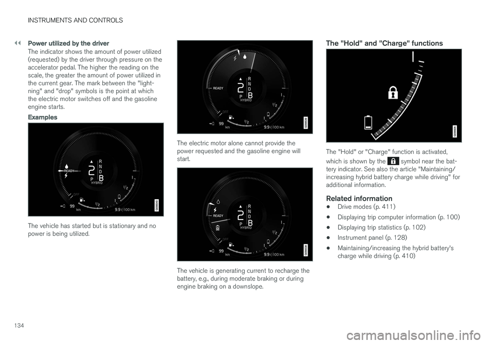
Power utilized by the driver
The indicator shows the amount of power utilized (requested) by the driver through pressure on theaccelerator pedal. The higher the reading on thescale, the greater the amount of power utilized inthe current gear. The mark between the "light-ning" and "drop" symbols is the point at whichthe electric motor switches off and the gasolineengine starts.
Examples
The vehicle has started but is stationary and no power is being utilized.
The electric motor alone cannot provide the power requested and the gasoline engine willstart.
The vehicle is generating current to recharge the battery, e.g., during moderate braking or duringengine braking on a downslope.
The "Hold" and "Charge" functions
The "Hold" or "Charge" function is activated, which is shown by the
symbol near the bat-
tery indicator. See also the article "Maintaining/ increasing hybrid battery charge while driving" foradditional information.
Related information
• Drive modes (p. 411)
• Displaying trip computer information (p. 100)
• Displaying trip statistics (p. 102)
• Instrument panel (p. 128)
• Maintaining/increasing the hybrid battery'scharge while driving (p. 410)
Page 138 of 580
||
INSTRUMENTS AND CONTROLS
136
BSD 2-clause “Simplified” license
Copyright ©)
reserved. Redistribution and use in source and binary forms, with or without modification, are permittedprovided that the following conditions are met:
1. Redistributions of source code must retain the above copyright notice, this list of conditions and the following disclaimer.
2. Redistributions in binary form must reproduce the above copyright notice, this listof conditions and the following disclaimer inthe documentation and/or other materialsprovided with the distribution.
THIS SOFTWARE IS PROVIDED BY THECOPYRIGHT HOLDERS AND CONTRIBUTORS"AS IS" AND ANY EXPRESS OR IMPLIEDWARRANTIES, INCLUDING, BUT NOT LIMITEDTO, THE IMPLIED WARRANTIES OFMERCHANTABILITY AND FITNESS FOR APARTICULAR PURPOSE ARE DISCLAIMED. INNO EVENT SHALL THE COPYRIGHT OWNEROR CONTRIBUTORS BE LIABLE FOR ANYDIRECT, INDIRECT, INCIDENTAL, SPECIAL,EXEMPLARY, OR CONSEQUENTIAL DAMAGES(INCLUDING, BUT NOT LIMITED TO,PROCUREMENT OF SUBSTITUTE GOODS ORSERVICES; LOSS OF USE, DATA, OR PROFITS;OR BUSINESS INTERRUPTION) HOWEVERCAUSED AND ON ANY THEORY OF LIABILITY,WHETHER IN CONTRACT, STRICT LIABILITY, OR TORT (INCLUDING NEGLIGENCE OROTHERWISE) ARISING IN ANY WAY OUT OFTHE USE OF THIS SOFTWARE, EVEN IFADVISED OF THE POSSIBILITY OF SUCHDAMAGE. The views and conclusions contained in the software and documentation are those of theauthors and should not be interpreted asrepresenting official policies, either expressed orimplied, of the FreeBSD Project.
FreeType Project License1. 1 Copyright 1996-1999 by David Turner,
Robert Wilhelm, and Werner LembergIntroduction The FreeType Project isdistributed in several archive packages; someof them may contain, in addition to theFreeType font engine, various tools andcontributions which rely on, or relate to, theFreeType Project. This license applies to allfiles found in such packages, and which donot fall under their own explicit license. Thelicense affects thus the FreeType fontengine, the test programs, documentationand makefiles, at the very least. This licensewas inspired by the BSD, Artistic, and IJG(Independent JPEG Group) licenses, whichall encourage inclusion and use of freesoftware in commercial and freewareproducts alike. As a consequence, its mainpoints are that: o We don't promise that thissoftware works. However, we are beinterested in any kind of bug reports. (`as is' distribution) o You can use this software forwhatever you want, in parts or full form,without having to pay us. (`royalty-free'usage) o You may not pretend that you wrotethis software. If you use it, or only parts of it,in a program, you must acknowledgesomewhere in your documentation thatyou've used the FreeType code. (`credits')We specifically permit and encourage theinclusion of this software, with or withoutmodifications, in commercial products,provided that all warranty or liability claimsare assumed by the product vendor. LegalTerms 0. Definitions Throughout this license,the terms `package', `FreeType Project', and`FreeType archive' refer to the set of filesoriginally distributed by the authors (DavidTurner, Robert Wilhelm, and WernerLemberg) as the `FreeType project', be theynamed as alpha, beta or final release. `You'refers to the licensee, or person using theproject, where `using' is a generic termincluding compiling the project's source codeas well as linking it to form a `program' or`executable'. This program is referred to as `aprogram using the FreeType engine'. Thislicense applies to all files distributed in theoriginal FreeType archive, including all sourcecode, binaries and documentation, unlessotherwise stated in the file in its original,unmodified form as distributed in the originalarchive. If you are unsure whether or not aparticular file is covered by this license, you