lock YAMAHA BANSHEE 350 2006 Notices Demploi (in French)
[x] Cancel search | Manufacturer: YAMAHA, Model Year: 2006, Model line: BANSHEE 350, Model: YAMAHA BANSHEE 350 2006Pages: 400, PDF Size: 3.59 MB
Page 290 of 400
2
2
11
3
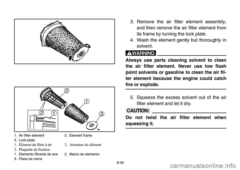
1. Air filter element 2. Element frame
3. Lock plate
1. Elément du filtre à air 2. Armature du elément
3. Plaquette de fixation
1. Elemento filtrante de aire 2. Marco de elemento
3. Placa de cierre
8-45
3. Remove the air filter element assembly,
and then remove the air filter element from
its frame by turning the lock plate.
4. Wash the element gently but thoroughly in
solvent.
w
Always use parts cleaning solvent to clean
the air filter element. Never use low flash
point solvents or gasoline to clean the air fil-
ter element because the engine could catch
fire or explode.
5. Squeeze the excess solvent out of the air
filter element and let it dry.
cC
Do not twist the air filter element when
squeezing it.
Page 292 of 400
8-47
6. Inspect the air filter element and replace it
if damaged.
7. Apply foam air filter oil to the air filter ele-
ment.
NOTE:
The air filter element should be wet but not drip-
ping.
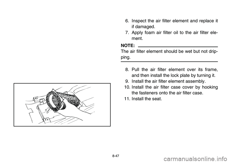
8. Pull the air filter element over its frame,
and then install the lock plate by turning it.
9. Install the air filter element assembly.
10. Install the air filter case cover by hooking
the fasteners onto the air filter case.
11. Install the seat.
Page 310 of 400
8-65
7. Tighten the carburetor cap securing plate
screw to the specified torque.
8. Tighten the carburetor joint screws.
Adjusting the throttle cables
NOTE:
After the jet needle clip position is changed, the
throttle cables may need to be adjusted.
1. Move the throttle lever a few times.
2. Push the throttle lever forward until it stops
and hold it in this position.
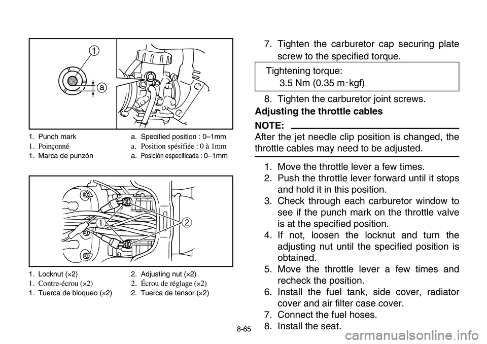
3. Check through each carburetor window to
see if the punch mark on the throttle valve
is at the specified position.
4. If not, loosen the locknut and turn the
adjusting nut until the specified position is
obtained.
5. Move the throttle lever a few times and
recheck the position.
6. Install the fuel tank, side cover, radiator
cover and air filter case cover.
7. Connect the fuel hoses.
8. Install the seat.
a
1
wq
1. Punch mark a. Specified position : 0–1mm
1. Poinçonné a. Position spésifiée : 0 à 1mm
1. Marca de punzón a.Posición especificada : 0–1mm
1. Locknut (×2) 2. Adjusting nut (×2)
1. Contre-écrou (×2) 2. Écrou de réglage (×2)
1. Tuerca de bloqueo (×2) 2. Tuerca de tensor (×2)
Tightening torque:
3.5 Nm (0.35 m0kgf)
Page 316 of 400
8-71
EBU00307
Throttle lever adjustment
NOTE:
Adjust the engine idling speed before adjusting
the throttle lever free play.
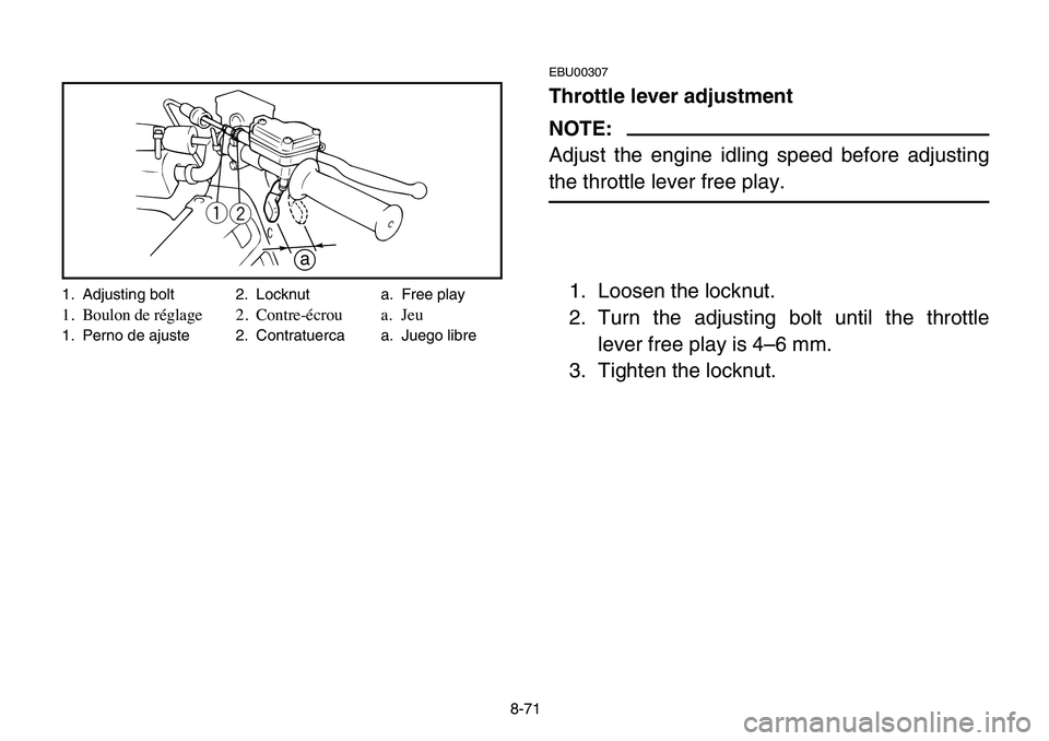
1. Loosen the locknut.
2. Turn the adjusting bolt until the throttle
lever free play is 4–6 mm.
3. Tighten the locknut.
qw
a
1. Adjusting bolt 2. Locknut a. Free play
1. Boulon de réglage 2. Contre-écrou a. Jeu
1. Perno de ajuste 2. Contratuerca a. Juego libre
Page 322 of 400
8-77
8Refill with the same type of brake fluid. Mixing
fluids may result in a harmful chemical reac-
tion and lead to poor brake performance.
8Be careful that water does not enter the brake
fluid reservoir when refilling. Water will signifi-
cantly lower the boiling point of the fluid and
may result in vapor lock.
8Brake fluid may deteriorate painted surfaces
or plastic parts. Always clean up spilled fluid
immediately.
8Have a Yamaha dealer check the cause if the
brake fluid level goes down.
Page 330 of 400
8-85
EBU11920
Parking brake adjustment
Parking brake adjustment may be required if the
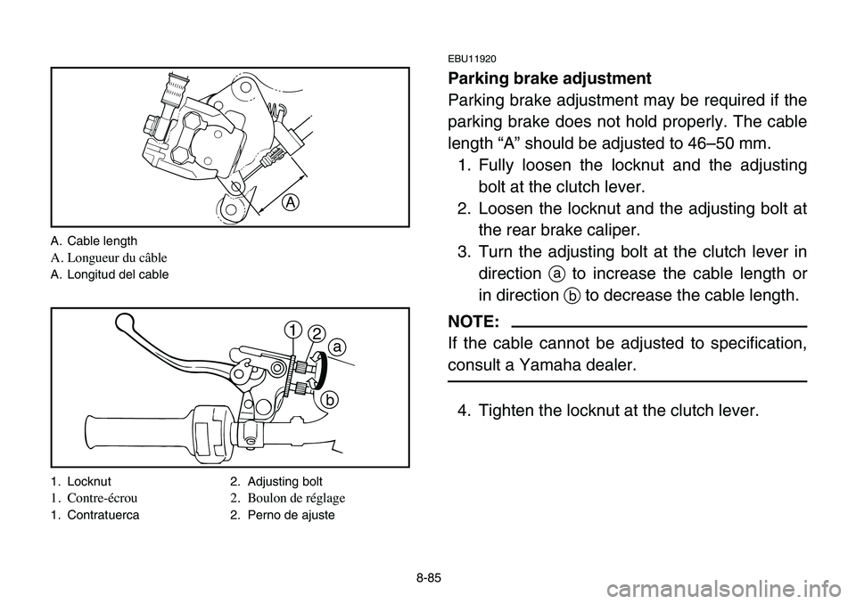
parking brake does not hold properly. The cable
length “A” should be adjusted to 46–50 mm.
1. Fully loosen the locknut and the adjusting
bolt at the clutch lever.
2. Loosen the locknut and the adjusting bolt at
the rear brake caliper.
3. Turn the adjusting bolt at the clutch lever in
directionato increase the cable length or
in direction bto decrease the cable length.
NOTE:
If the cable cannot be adjusted to specification,
consult a Yamaha dealer.
4. Tighten the locknut at the clutch lever.
A
a
b 1
2
A. Cable length
A. Longueur du câble
A. Longitud del cable
1. Locknut 2. Adjusting bolt
1. Contre-écrou 2. Boulon de réglage
1. Contratuerca 2. Perno de ajuste
Page 332 of 400
8-87
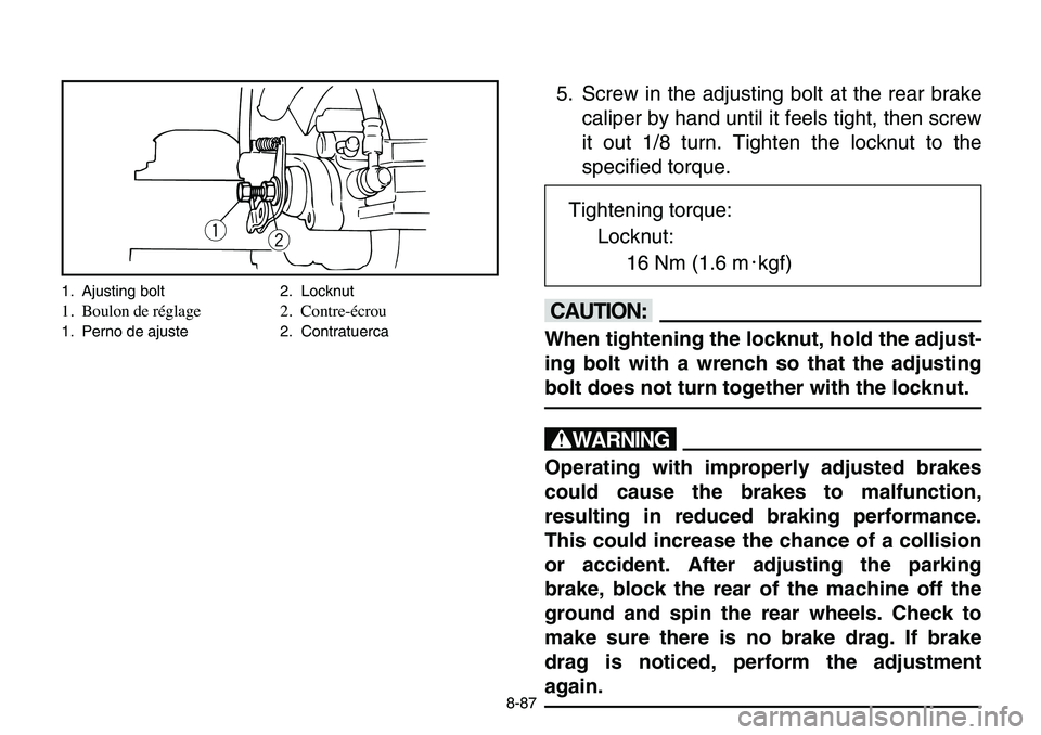
5. Screw in the adjusting bolt at the rear brake
caliper by hand until it feels tight, then screw
it out 1/8 turn. Tighten the locknut to the
specified torque.
cC
When tightening the locknut, hold the adjust-
ing bolt with a wrench so that the adjusting
bolt does not turn together with the locknut.
w
Operating with improperly adjusted brakes
could cause the brakes to malfunction,
resulting in reduced braking performance.
This could increase the chance of a collision
or accident. After adjusting the parking
brake, block the rear of the machine off the
ground and spin the rear wheels. Check to
make sure there is no brake drag. If brake
drag is noticed, perform the adjustment
again.
qw
1. Ajusting bolt 2. Locknut
1. Boulon de réglage 2. Contre-écrou
1. Perno de ajuste 2. Contratuerca
Tightening torque:
Locknut:
16 Nm (1.6 m0kgf)
Page 336 of 400
8-91
EBU00539
Clutch adjustment
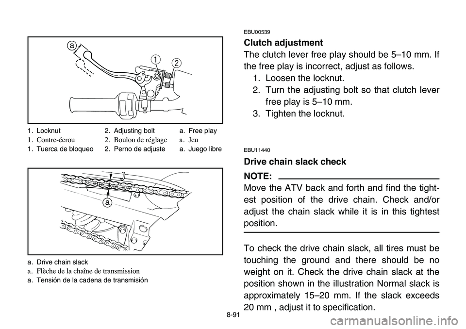
The clutch lever free play should be 5–10 mm. If
the free play is incorrect, adjust as follows.
1. Loosen the locknut.
2. Turn the adjusting bolt so that clutch lever
free play is 5–10 mm.
3. Tighten the locknut.
EBU11440
Drive chain slack check
NOTE:
Move the ATV back and forth and find the tight-
est position of the drive chain. Check and/or
adjust the chain slack while it is in this tightest
position.
To check the drive chain slack, all tires must be
touching the ground and there should be no
weight on it. Check the drive chain slack at the
position shown in the illustration Normal slack is
approximately 15–20 mm. If the slack exceeds
20 mm , adjust it to specification.
q
w
a
a
1. Locknut 2. Adjusting bolt a. Free play
1. Contre-écrou 2. Boulon de réglage a. Jeu
1. Tuerca de bloqueo 2. Perno de adjuste a. Juego libre
a. Drive chain slack
a. Flèche de la chaîne de transmission
a. Tensión de la cadena de transmisión
Page 338 of 400
8-93
EBU00351
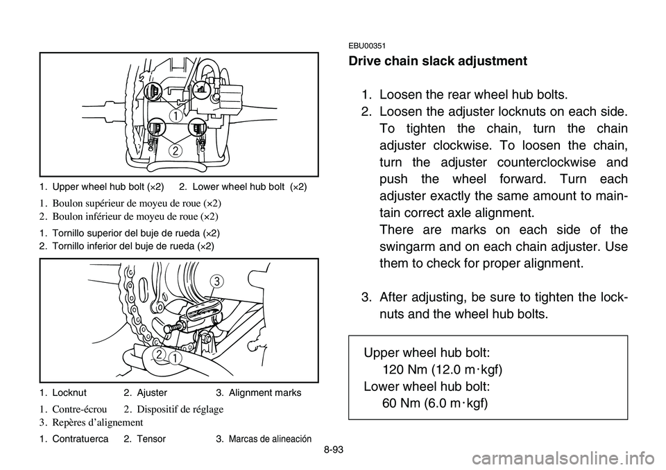
Drive chain slack adjustment
1. Loosen the rear wheel hub bolts.
2. Loosen the adjuster locknuts on each side.
To tighten the chain, turn the chain
adjuster clockwise. To loosen the chain,
turn the adjuster counterclockwise and
push the wheel forward. Turn each
adjuster exactly the same amount to main-
tain correct axle alignment.
There are marks on each side of the
swingarm and on each chain adjuster. Use
them to check for proper alignment.
3. After adjusting, be sure to tighten the lock-
nuts and the wheel hub bolts.
q
w
e
q w
1. Upper wheel hub bolt (×2) 2. Lower wheel hub bolt (×2)
1. Boulon supérieur de moyeu de roue (×2)
2. Boulon inférieur de moyeu de roue (×2)
1. Tornillo superior del buje de rueda (×2)
2. Tornillo inferior del buje de rueda (×2)
1. Locknut 2. Ajuster 3. Alignment marks
1. Contre-écrou 2. Dispositif de réglage
3. Repères d’alignement
1. Contratuerca 2.Tensor3.Marcas de alineación
Upper wheel hub bolt:
120 Nm (12.0 m0kgf)
Lower wheel hub bolt:
60 Nm (6.0 m0kgf)
Page 354 of 400
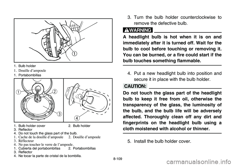
3. Turn the bulb holder counterclockwise to
remove the defective bulb.
w
A headlight bulb is hot when it is on and
immediately after it is turned off. Wait for the
bulb to cool before touching or removing it.
You can be burned, or a fire could start if the
bulb touches something flammable.
4. Put a new headlight bulb into position and
secure it in place with the bulb holder.
cC
Do not touch the glass part of the headlight
bulb to keep it free from oil, otherwise the
transparency of the glass, the luminosity of
the bulb, and the bulb life will be adversely
affected. Thoroughly clean off any dirt and
fingerprints on the headlight bulb using a
cloth moistened with alcohol or thinner.
5. Install the bulb holder cover.
1
e qw
r
1. Bulb holder
1. Douille d’ampoule
1. Portabombillas
1. Bulb holder cover 2. Bulb holder
3. Reflector
4. Do not touch the glass part of the bulb.
1. Cache de la douille d’ampoule 2. Douille d’ampoule
3. Réflecteur
4. Ne pas toucher le verre de l’ampoule.
1. Cubierta del portabombillas 2. Portabombillas
3. Reflector
4. Ne tocar la parte de cristal de la bombilla.
8-109