headlight YAMAHA BEAR TRACKER 250 2003 Owners Manual
[x] Cancel search | Manufacturer: YAMAHA, Model Year: 2003, Model line: BEAR TRACKER 250, Model: YAMAHA BEAR TRACKER 250 2003Pages: 378, PDF Size: 13.9 MB
Page 18 of 378
Wheel removal .................................. 8-65
Wheel installation ............................... 8-67
Battery ............................................... 8-69
Replenishing the battery fluid ............. 8-73
Fuse replacement .............................. 8-77
Replacing a headlight bulb ................. 8-79
Headlight beam adjustment................ 8-81
Tail/brake light bulb replacement ....... 8-83
Troubleshooting ................................. 8-87
Troubleshooting chart ........................ 8-89
CLEANING AND STORAGE .................. 9-1
A. Cleaning .......................................... 9-1
B. Storage ........................................... 9-7
SPECIFICATIONS ................................ 10-1
CONVERSION TABLE .......................... 11-1
91011U4XE64.book Page 3 Thursday, May 30, 2002 1:49 PM
Page 66 of 378
3-1
EBU00032
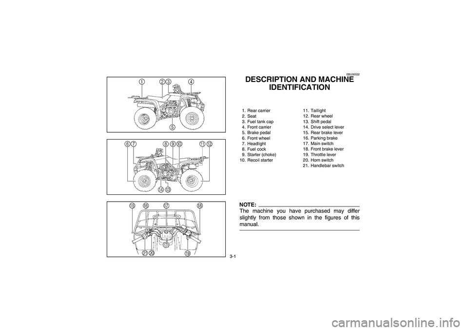
DESCRIPTION AND MACHINE
IDENTIFICATION1. Rear carrier
2. Seat
3. Fuel tank cap
4. Front carrier
5. Brake pedal
6. Front wheel
7. Headlight
8. Fuel cock
9. Starter (choke)
10. Recoil starter11. Taillight
12. Rear wheel
13. Shift pedal
14. Drive select lever
15. Rear brake lever
16. Parking brake
17. Main switch
18. Front brake lever
19. Throttle lever
20. Horn switch
21. Handlebar switchNOTE:The machine you have purchased may differ
slightly from those shown in the figures of this
manual.
U4XE64.book Page 1 Thursday, May 30, 2002 1:49 PM
Page 76 of 378
4-1
EBU00040
CONTROL FUNCTIONS
EBU00942
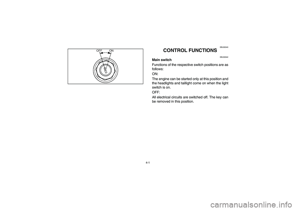
Main switch
Functions of the respective switch positions are as
follows:
ON:
The engine can be started only at this position and
the headlights and taillight come on when the light
switch is on.
OFF:
All electrical circuits are switched off. The key can
be removed in this position.
U4XE64.book Page 1 Thursday, May 30, 2002 1:49 PM
Page 82 of 378
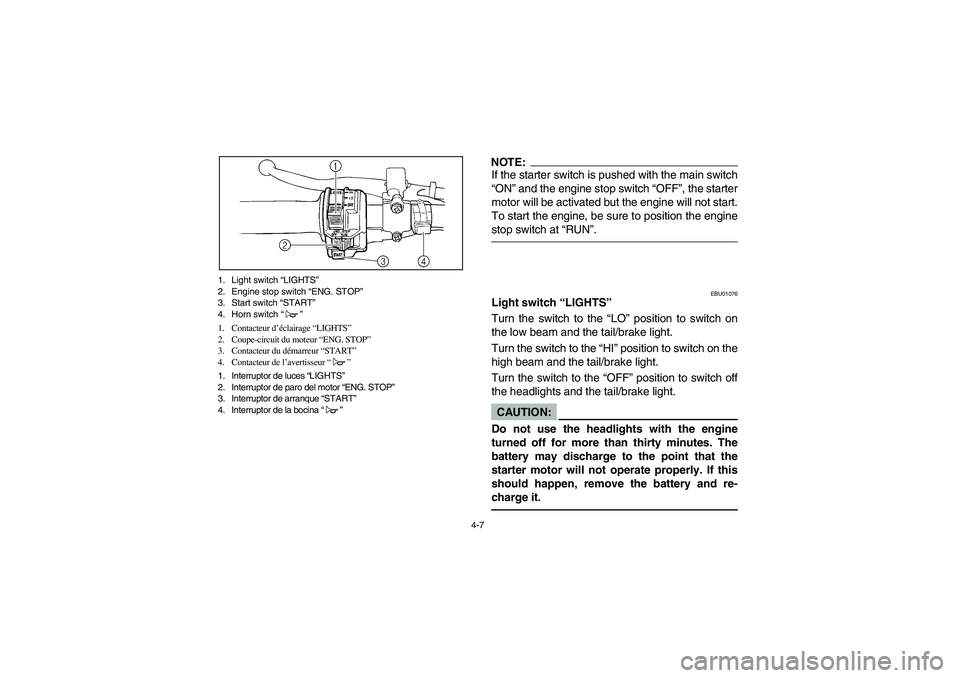
4-7 1. Light switch “LIGHTS”
2. Engine stop switch “ENG. STOP”
3. Start switch “START”
4. Horn switch “”
1. Contacteur d’éclairage “LIGHTS”
2. Coupe-circuit du moteur “ENG. STOP”
3. Contacteur du démarreur “START”
4. Contacteur de l’avertisseur “”
1. Interruptor de luces “LIGHTS”
2. Interruptor de paro del motor “ENG. STOP”
3. Interruptor de arranque “START”
4. Interruptor de la bocina “”
NOTE:If the starter switch is pushed with the main switch
“ON” and the engine stop switch “OFF”, the starter
motor will be activated but the engine will not start.
To start the engine, be sure to position the engine
stop switch at “RUN”.
EBU01076
Light switch “LIGHTS”
Turn the switch to the “LO” position to switch on
the low beam and the tail/brake light.
Turn the switch to the “HI” position to switch on the
high beam and the tail/brake light.
Turn the switch to the “OFF” position to switch off
the headlights and the tail/brake light.CAUTION:
Do not use the headlights with the engine
turned off for more than thirty minutes. The
battery may discharge to the point that the
starter motor will not operate properly. If this
should happen, remove the battery and re-
charge it.
U4XE64.book Page 7 Thursday, May 30, 2002 1:49 PM
Page 128 of 378
5-19
EBU00152
Fittings and Fasteners
Always check the tightness of chassis fittings and
fasteners before a ride. Take the machine to a
Yamaha dealer or refer to the Service Manual for
correct tightening torque.
EBU00991
Lights
Check the headlights and tail/brake light to make
sure they are in working condition. Repair as nec-
essary for proper operation.
EBU01082
Switches
Check the operation of all switches. Repair as nec-
essary for proper operation.
EBU00499
Battery
Check fluid level and fill if necessary. Use only dis-
tilled water if refilling is necessary. (See pages
8-69–8-75.)
U4XE64.book Page 19 Thursday, May 30, 2002 1:49 PM
Page 332 of 378
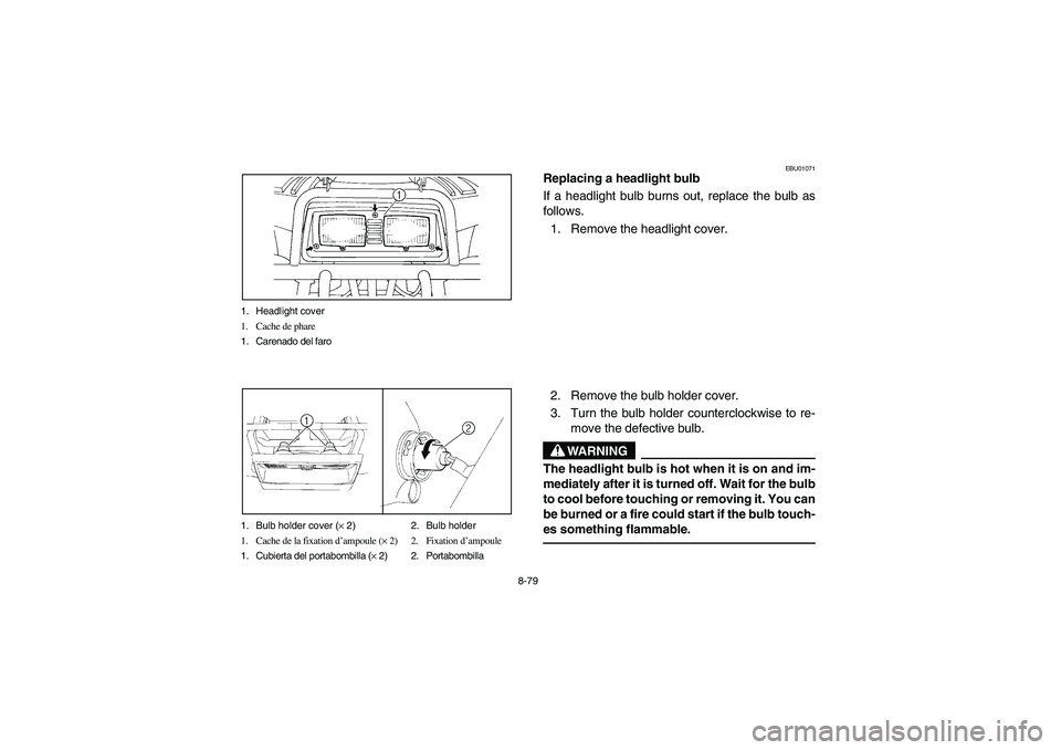
8-79 1. Headlight cover
1. Cache de phare
1. Carenado del faro
1. Bulb holder cover (× 2) 2. Bulb holder
1. Cache de la fixation d’ampoule (× 2) 2. Fixation d’ampoule
1. Cubierta del portabombilla (× 2) 2. Portabombilla
EBU01071
Replacing a headlight bulb
If a headlight bulb burns out, replace the bulb as
follows.
1. Remove the headlight cover.
2. Remove the bulb holder cover.
3. Turn the bulb holder counterclockwise to re-
move the defective bulb.
WARNING
The headlight bulb is hot when it is on and im-
mediately after it is turned off. Wait for the bulb
to cool before touching or removing it. You can
be burned or a fire could start if the bulb touch-
es something flammable.
U4XE64.book Page 79 Thursday, May 30, 2002 1:49 PM
Page 334 of 378
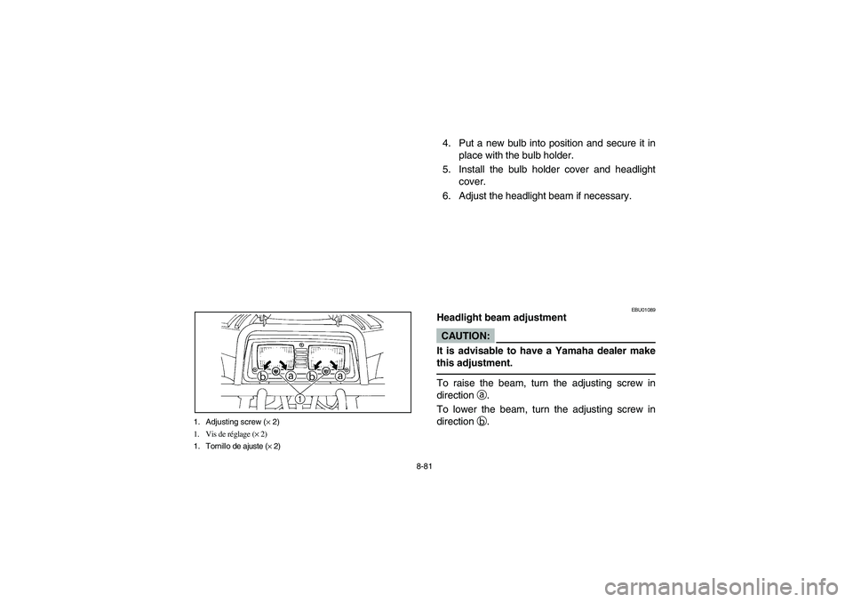
8-81 1. Adjusting screw (× 2)
1. Vis de réglage (× 2)
1. Tornillo de ajuste (× 2)
4. Put a new bulb into position and secure it in
place with the bulb holder.
5. Install the bulb holder cover and headlight
cover.
6. Adjust the headlight beam if necessary.
EBU01089
Headlight beam adjustmentCAUTION:
It is advisable to have a Yamaha dealer make
this adjustment. To raise the beam, turn the adjusting screw in
direction
a.
To lower the beam, turn the adjusting screw in
direction
b.
U4XE64.book Page 81 Thursday, May 30, 2002 1:49 PM
Page 360 of 378
10-5
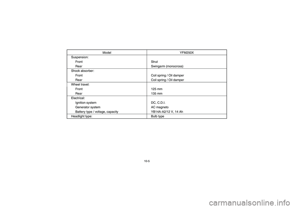
Suspension:
Fr on t S tr ut
Rear Swingarm (monocross)
Shock absorber:
Front Coil spring / Oil damper
Rear Coil spring / Oil damper
Wheel travel:
Front 125 mm
Rear 135 mm
Electrical:
Ignition system DC, C.D.I.
Generator system AC magneto
Battery type / voltage, capacity YB14A-A2/12 V, 14 Ah
Headlight type: Bulb typeModel YFM250X
U4XE64.book Page 5 Thursday, May 30, 2002 1:49 PM
Page 361 of 378
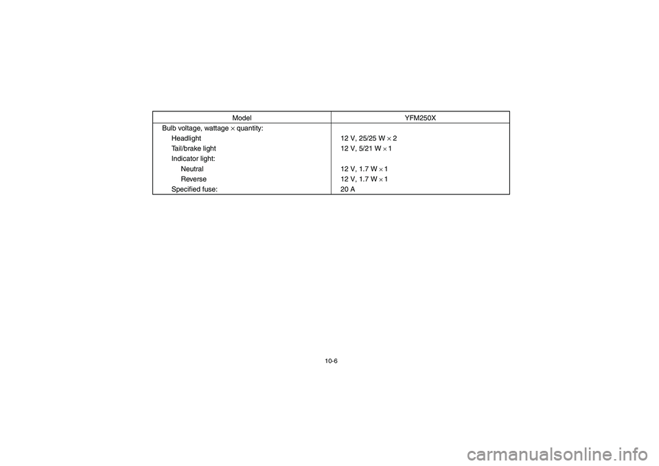
10-6
Bulb voltage, wattage
× quantity:
Headlight 12 V, 25/25 W
× 2
Tail/brake light 12 V, 5/21 W
× 1
Indicator light:
Neutral 12 V, 1.7 W
× 1
Reverse 12 V, 1.7 W × 1
Specified fuse: 20 AModel YFM250X
U4XE64.book Page 6 Thursday, May 30, 2002 1:49 PM