lock YAMAHA BLASTER 200 2004 Manuale de Empleo (in Spanish)
[x] Cancel search | Manufacturer: YAMAHA, Model Year: 2004, Model line: BLASTER 200, Model: YAMAHA BLASTER 200 2004Pages: 386, tamaño PDF: 7.52 MB
Page 301 of 386

8-53
EBU00307
Throttle lever adjustment
NOTE:
Adjust the engine idling speed before adjusting
the throttle lever free play.
1. Loosen the locknut.
2. Turn the adjusting bolt until the throttle lever
free play is 4–6 mm.
3. Tighten the locknut.
qw
a
1. Adjusting bolt 2. Locknut a. Free play1. Boulon de réglage 2. Contre-écrou a. Jeu1. Perno de ajuste 2. Contratuerca a. Juego libre
5VM-9-61-05 3/14/03 10:48 PM Page 54
Page 305 of 386

8Refill with the same type of brake fluid.
Mixing fluids may result in a harmful chemi-
cal reaction and lead to poor brake perfor-
mance.
8Be careful that water does not enter the
brake fluid reservoir when refilling. Water
will significantly lower the boiling point of the
fluid and may result in vapor lock.
8Brake fluid may deteriorate painted surfaces
or plastic parts. Always clean up spilled fluid
immediately.
8Have a Yamaha dealer check the cause if
the brake fluid level goes down.
EBU01186
Brake fluid replacement
Complete fluid replacement should be done only
by trained Yamaha service personnel. Have a
Yamaha dealer replace the following compo-
nents during periodic maintenance or when they
are damaged or leaking.
8Replace the oil seals every two years.
8Replace the brake hoses every four years.
8-57
5VM-9-61-05 3/14/03 10:48 PM Page 58
Page 313 of 386
8-65
A
a
b 1
2
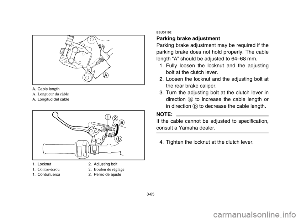
A. Cable lengthA. Longueur du câbleA. Longitud del cable
1. Locknut 2. Adjusting bolt
1. Contre-écrou 2. Boulon de réglage1. Contratuerca 2. Perno de ajuste
EBU01192
Parking brake adjustment
Parking brake adjustment may be required if the
parking brake does not hold properly. The cable
length “A” should be adjusted to 64–68 mm.
1. Fully loosen the locknut and the adjusting
bolt at the clutch lever.
2. Loosen the locknut and the adjusting bolt at
the rear brake caliper.
3. Turn the adjusting bolt at the clutch lever in
direction ato increase the cable length or
in direction bto decrease the cable length.
NOTE:
If the cable cannot be adjusted to specification,
consult a Yamaha dealer.
4. Tighten the locknut at the clutch lever.
5VM-9-61-05 3/14/03 10:48 PM Page 66
Page 315 of 386
1
2
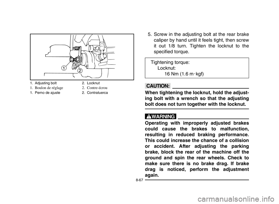
5. Screw in the adjusting bolt at the rear brake
caliper by hand until it feels tight, then screw
it out 1/8 turn. Tighten the locknut to the
specified torque.
cC
When tightening the locknut, hold the adjust-
ing bolt with a wrench so that the adjusting
bolt does not turn together with the locknut.
w
Operating with improperly adjusted brakes
could cause the brakes to malfunction,
resulting in reduced braking performance.
This could increase the chance of a collision
or accident. After adjusting the parking
brake, block the rear of the machine off the
ground and spin the rear wheels. Check to
make sure there is no brake drag. If brake
drag is noticed, perform the adjustment
again.
Tightening torque:
Locknut:
16 Nm (1.6 m0kgf)
1. Adjusting bolt 2. Locknut1. Boulon de réglage 2. Contre-écrou1. Perno de ajuste 2. Contratuerca
8-67
5VM-9-61-05 3/14/03 10:48 PM Page 68
Page 319 of 386

8-71
EBU00539
Clutch adjustment
The clutch lever free play should be 5–10 mm. If
the free play is incorrect, adjust as follows.
1. Loosen the locknut.
2. Turn the adjusting bolt so that clutch lever
free play is 5–10 mm.
3. Tighten the locknut.
EBU00349
Autolube pump adjustment
The Autolube pump is a vital part of the engine
and requires very sophisticated adjustment.
Most adjusting should be left to a Yamaha deal-
er who has the professional knowledge and
experience to do so.
q
w
a
1. Locknut 2. Adjusting bolt a. Free play1. Contre-écrou 2. Boulon de réglage a. Jeu1. Contratuerca 2. Perno de ajuste a. Juego libre
5VM-9-61-05 3/14/03 10:48 PM Page 72
Page 323 of 386
8-75
EBU00351
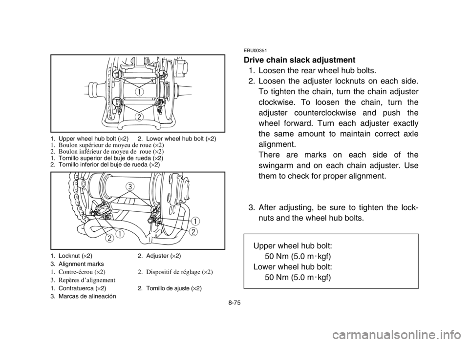
Drive chain slack adjustment
1. Loosen the rear wheel hub bolts.
2. Loosen the adjuster locknuts on each side.
To tighten the chain, turn the chain adjuster
clockwise. To loosen the chain, turn the
adjuster counterclockwise and push the
wheel forward. Turn each adjuster exactly
the same amount to maintain correct axle
alignment.
There are marks on each side of the
swingarm and on each chain adjuster. Use
them to check for proper alignment.
3. After adjusting, be sure to tighten the lock-
nuts and the wheel hub bolts.
q
w
e
q
wqw
1. Upper wheel hub bolt (×2) 2. Lower wheel hub bolt (×2)1. Boulon supérieur de moyeu de roue (×2)
2. Boulon inférieur de moyeu de roue (×2)1. Tornillo superior del buje de rueda (×2)
2. Tornillo inferior del buje de rueda (×2)
1. Locknut (×2) 2. Adjuster (×2)
3. Alignment marks
1. Contre-écrou (×2) 2. Dispositif de réglage (×2)
3. Repères d’alignement
1. Contratuerca (×2) 2. Tornillo de ajuste (×2)
3. Marcas de alineación
Upper wheel hub bolt:
50 Nm (5.0 m0kgf)
Lower wheel hub bolt:
50 Nm (5.0 m0kgf)
5VM-9-61-05 3/14/03 10:48 PM Page 76
Page 341 of 386
1
2
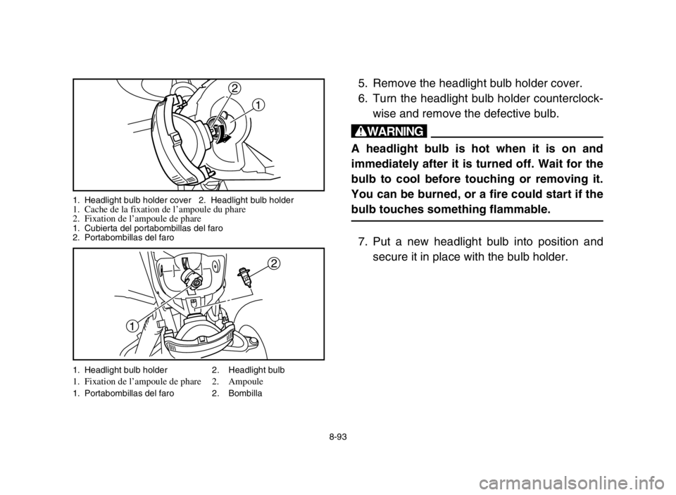
5. Remove the headlight bulb holder cover.
6. Turn the headlight bulb holder counterclock-
wise and remove the defective bulb.
w
A headlight bulb is hot when it is on and
immediately after it is turned off. Wait for the
bulb to cool before touching or removing it.
You can be burned, or a fire could start if the
bulb touches something flammable.
7. Put a new headlight bulb into position and
secure it in place with the bulb holder.
1. Headlight bulb holder 2. Headlight bulb1. Fixation de l’ampoule de phare 2. Ampoule1. Portabombillas del faro 2. Bombilla
8-93
1 2
1. Headlight bulb holder cover 2. Headlight bulb holder1. Cache de la fixation de l’ampoule du phare
2. Fixation de l’ampoule de phare
1. Cubierta del portabombillas del faro
2. Portabombillas del faro
5VM-9-61-05 3/14/03 10:48 PM Page 94
Page 347 of 386
8-99
EBU00861
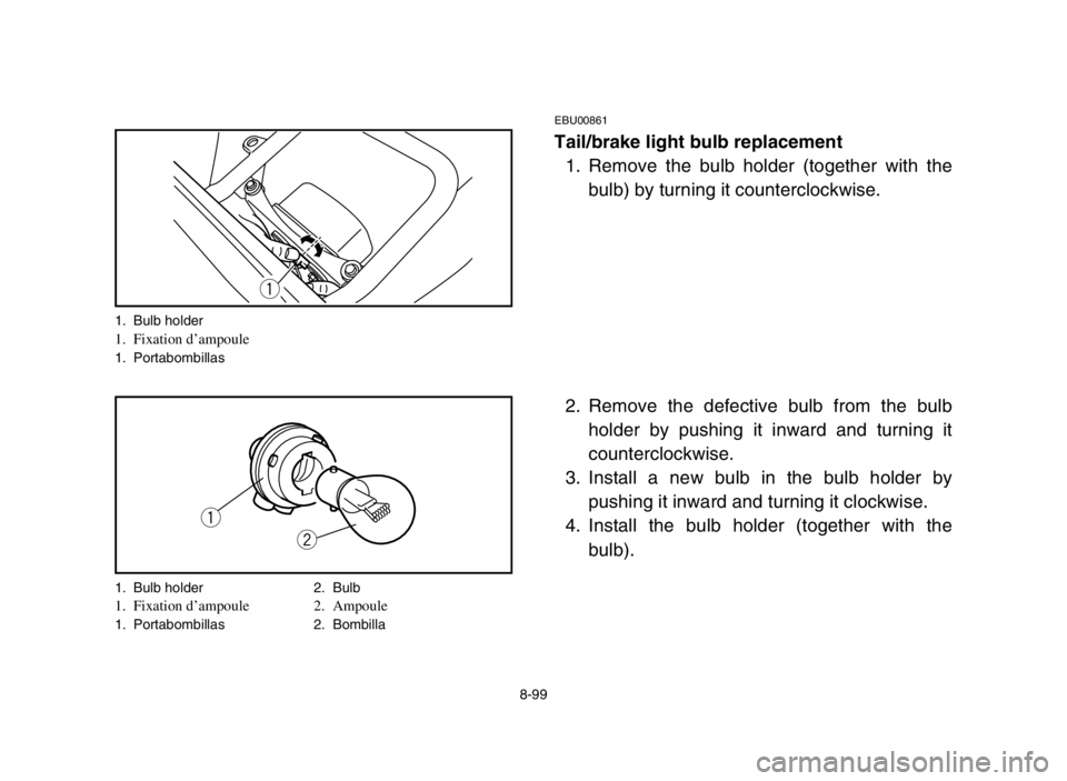
Tail/brake light bulb replacement
1. Remove the bulb holder (together with the
bulb) by turning it counterclockwise.
2. Remove the defective bulb from the bulb
holder by pushing it inward and turning it
counterclockwise.
3. Install a new bulb in the bulb holder by
pushing it inward and turning it clockwise.
4. Install the bulb holder (together with the
bulb).
q
q
w
1. Bulb holder1. Fixation d’ampoule1. Portabombillas
1. Bulb holder 2. Bulb
1. Fixation d’ampoule 2. Ampoule1. Portabombillas 2. Bombilla
5VM-9-61-05 3/14/03 10:48 PM Page 100
Page 357 of 386

9-1
EBU00418
CLEANING AND STORAGE
A. CLEANING
Frequent, thorough cleaning of your machine
will not only enhance its appearance but will
improve its general performance and extend the
useful life of many components.
1. Before cleaning the machine:
a. Block off the end of the exhaust pipe to pre-
vent water entry. A plastic bag and strong
rubber band may be used.
b. Make sure the spark plug and all filler caps
are properly installed.
2. If the engine case is excessively greasy,
apply degreaser with a paint brush. Do not
apply degreaser to the chain, sprockets or
wheel axles.
3. Rinse the dirt and degreaser off with a gar-
den hose. Use only enough pressure to do
the job.
5VM-9-61-06 3/14/03 9:40 PM Page 2
Page 365 of 386

9-9
4. Lubricate all control cables.
5. Block up the frame to raise all wheels off the
ground.
6. Tie a plastic bag over the exhaust pipe out-
let to prevent moisture from entering.
7. If storing in a humid or salt-air atmosphere,
coat all exposed metal surfaces with a light
film of oil. Do not apply oil to any rubber
parts or the seat cover.
NOTE:
Make any necessary repairs before storing the
machine.
5VM-9-61-06 3/14/03 9:40 PM Page 10