light YAMAHA BLASTER 200 2004 Manuale de Empleo (in Spanish)
[x] Cancel search | Manufacturer: YAMAHA, Model Year: 2004, Model line: BLASTER 200, Model: YAMAHA BLASTER 200 2004Pages: 386, tamaño PDF: 7.52 MB
Page 337 of 386
EBU01293
Replacing a headlight bulb
If a headlight bulb burns out, replace it as fol-
lows.
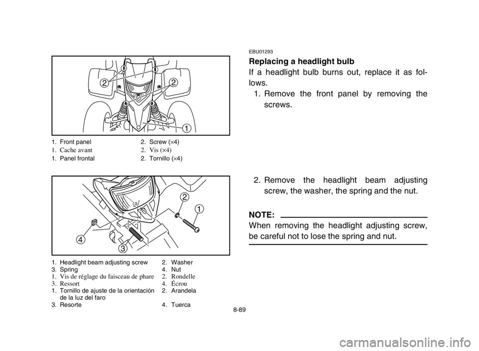
1. Remove the front panel by removing the
screws.
2. Remove the headlight beam adjusting
screw, the washer, the spring and the nut.
NOTE:
When removing the headlight adjusting screw,
be careful not to lose the spring and nut.
22
1
1. Front panel 2. Screw (×4)1. Cache avant 2. Vis (×4)1. Panel frontal 2. Tornillo (×4)
1
3
4
2
1. Headlight beam adjusting screw 2. Washer
3. Spring 4. Nut
1. Vis de réglage du faisceau de phare 2. Rondelle
3. Ressort 4.Écrou
1. Tornillo de ajuste de la orientación 2. Arandela
de la luz del faro
3. Resorte 4. Tuerca
8-89
5VM-9-61-05 3/14/03 10:48 PM Page 90
Page 339 of 386
8-91
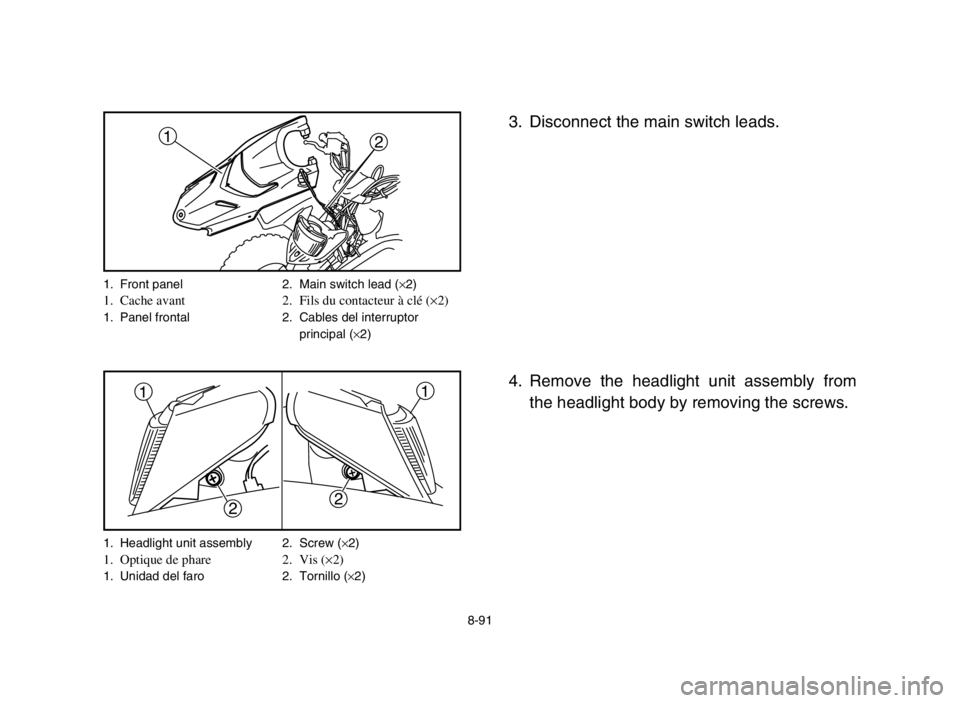
3. Disconnect the main switch leads.
4. Remove the headlight unit assembly from
the headlight body by removing the screws.
22
11
1. Headlight unit assembly 2. Screw (×2)1. Optique de phare 2. Vis (×2)1. Unidad del faro 2. Tornillo (×2)
12
1. Front panel 2. Main switch lead (×2)1. Cache avant 2. Fils du contacteur à clé (×2)1. Panel frontal 2. Cables del interruptor
principal (×2)
5VM-9-61-05 3/14/03 10:48 PM Page 92
Page 341 of 386
1
2
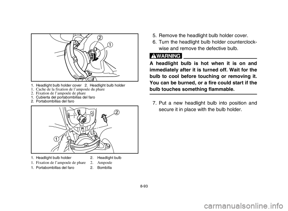
5. Remove the headlight bulb holder cover.
6. Turn the headlight bulb holder counterclock-
wise and remove the defective bulb.
w
A headlight bulb is hot when it is on and
immediately after it is turned off. Wait for the
bulb to cool before touching or removing it.
You can be burned, or a fire could start if the
bulb touches something flammable.
7. Put a new headlight bulb into position and
secure it in place with the bulb holder.
1. Headlight bulb holder 2. Headlight bulb1. Fixation de l’ampoule de phare 2. Ampoule1. Portabombillas del faro 2. Bombilla
8-93
1 2
1. Headlight bulb holder cover 2. Headlight bulb holder1. Cache de la fixation de l’ampoule du phare
2. Fixation de l’ampoule de phare
1. Cubierta del portabombillas del faro
2. Portabombillas del faro
5VM-9-61-05 3/14/03 10:48 PM Page 94
Page 343 of 386
a
22
11
cC
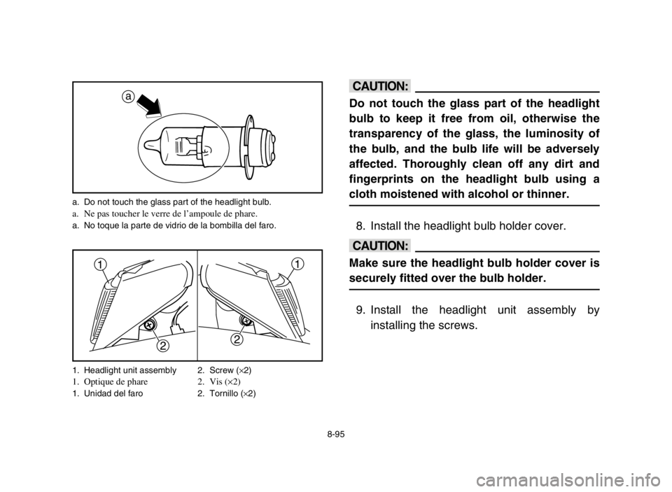
Do not touch the glass part of the headlight
bulb to keep it free from oil, otherwise the
transparency of the glass, the luminosity of
the bulb, and the bulb life will be adversely
affected. Thoroughly clean off any dirt and
fingerprints on the headlight bulb using a
cloth moistened with alcohol or thinner.
8. Install the headlight bulb holder cover.
cC
Make sure the headlight bulb holder cover is
securely fitted over the bulb holder.
9. Install the headlight unit assembly by
installing the screws.
a. Do not touch the glass part of the headlight bulb.a. Ne pas toucher le verre de l’ampoule de phare.a. No toque la parte de vidrio de la bombilla del faro.
8-95 1. Headlight unit assembly 2. Screw (×2)
1. Optique de phare 2. Vis (×2)1. Unidad del faro 2. Tornillo (×2)
5VM-9-61-05 3/14/03 10:48 PM Page 96
Page 345 of 386
a b
1
1. Adjusting screw 1. Vis de réglage1. Tornillo de ajuste
8-97
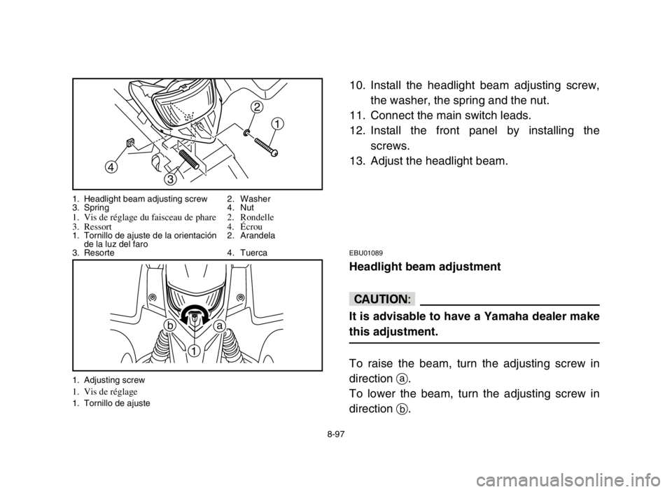
10. Install the headlight beam adjusting screw,
the washer, the spring and the nut.
11. Connect the main switch leads.
12. Install the front panel by installing the
screws.
13. Adjust the headlight beam.
EBU01089
Headlight beam adjustment
cC
It is advisable to have a Yamaha dealer make
this adjustment.
To raise the beam, turn the adjusting screw in
direction a.
To lower the beam, turn the adjusting screw in
direction b.
1
3
4
2
1. Headlight beam adjusting screw 2. Washer
3. Spring 4. Nut
1. Vis de réglage du faisceau de phare 2. Rondelle
3. Ressort 4.Écrou
1. Tornillo de ajuste de la orientación 2. Arandela
de la luz del faro
3. Resorte 4. Tuerca
5VM-9-61-05 3/14/03 10:48 PM Page 98
Page 347 of 386
8-99
EBU00861
Tail/brake light bulb replacement
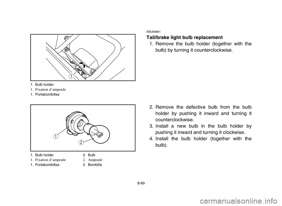
1. Remove the bulb holder (together with the
bulb) by turning it counterclockwise.
2. Remove the defective bulb from the bulb
holder by pushing it inward and turning it
counterclockwise.
3. Install a new bulb in the bulb holder by
pushing it inward and turning it clockwise.
4. Install the bulb holder (together with the
bulb).
q
q
w
1. Bulb holder1. Fixation d’ampoule1. Portabombillas
1. Bulb holder 2. Bulb
1. Fixation d’ampoule 2. Ampoule1. Portabombillas 2. Bombilla
5VM-9-61-05 3/14/03 10:48 PM Page 100
Page 351 of 386

8-103
w
Do not smoke when checking the fuel sys-
tem. Fuel can ignite or explode, causing
severe injury or property damage. Make sure
there are no open flames or sparks in the
area, including pilot lights from water
heaters or furnaces.
5VM-9-61-05 3/14/03 10:48 PM Page 104
Page 365 of 386

9-9
4. Lubricate all control cables.
5. Block up the frame to raise all wheels off the
ground.
6. Tie a plastic bag over the exhaust pipe out-
let to prevent moisture from entering.
7. If storing in a humid or salt-air atmosphere,
coat all exposed metal surfaces with a light
film of oil. Do not apply oil to any rubber
parts or the seat cover.
NOTE:
Make any necessary repairs before storing the
machine.
5VM-9-61-06 3/14/03 9:40 PM Page 10
Page 371 of 386

10-5
Model YFS200
Suspension:
Front suspension Double wishbone
Rear suspension Swingarm (monocross)
Shock absorber:
Front shock absorber Coil spring/Oil damper
Rear shock absorber Coil spring/Gas-oil damper
Wheel travel:
Front wheel travel 180 mm
Rear wheel travel 180 mm
Electrical:
Ignition system C.D.I.
Generator system C.D.I. magneto
Headlight type: Bulb type
Bulb voltage, wattage ×quantity:
Headlight 12V, 35 W/36.5 W ×1
Tail/brake light 12V, 5/21 W ×1
Oil level warning light 12V, 3.4 W ×1
5VM-9-61-06 3/14/03 9:40 PM Page 16