engine oil YAMAHA BT1100 2002 Owners Manual
[x] Cancel search | Manufacturer: YAMAHA, Model Year: 2002, Model line: BT1100, Model: YAMAHA BT1100 2002Pages: 96, PDF Size: 3.32 MB
Page 10 of 96
12
3
456
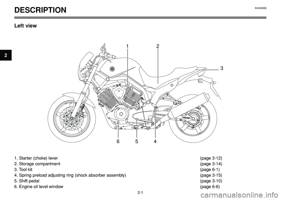
1. Starter (choke) lever(page 3-12)
2. Storage compartment(page 3-14)
3. Tool kit(page 6-1)
4. Spring preload adjusting ring (shock absorber assembly) (page 3-15)
5. Shift pedal(page 3-10)
6. Engine oil level window (page 6-6)
DESCRIPTION
Left view
EAU00026
2-1
2
Page 11 of 96
78910
1211
DESCRIPTIONEAU00026
2-2
2
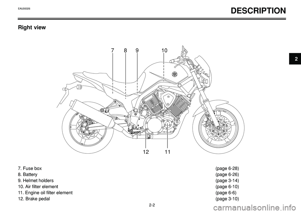
7. Fuse box (page 6-28)
8. Battery (page 6-26)
9. Helmet holders (page 3-14)
10. Air filter element (page 6-10)
11. Engine oil filter element (page 6-6)
12. Brake pedal (page 3-10)
Right view
Page 16 of 96
INSTRUMENT AND CONTROL FUNCTIONS
2
1
54 3
1
2
6 5 4
3
EAU00063
High beam indicator light “1”
This indicator light comes on when the
high beam of the headlight is switched on.
EAUB0002
Fuel level warning light “K”
This warning light comes on when the fuel
level drops below approximately 5.8 L.
When this occurs, refuel as soon as possi-
ble.
The electrical circuit of the warning light
can be checked according to the following
procedure.
1. Turn the key to “
I” (ON).
2. If the warning light does not come on,
have a Yamaha dealer check the
electrical circuit.
NOTE:
This model is equipped with a self-diagno-
sis device for the fuel level warning light
circuit. (See page 3-6 for an explanation of
the self-diagnosis device).
EAUB0003
Speedometer unit
The speedometer unit is equipped with the
following:
•a speedometer (which shows riding
speed)
•a tachometer (which shows engine
r/min)
•an odometer (which shows the total
distance traveled)
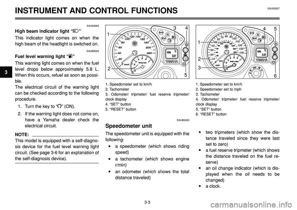
1. Speedometer set to km/h
2. Tachometer
3. Odometer/ tripmeter/ fuel reserve tripmeter/
clock display
4. “SET” button
5. “RESET” button
•two tripmeters (which show the dis-
tance traveled since they were last
set to zero)
•a fuel reserve tripmeter (which shows
the distance traveled on the fuel re-
serve)
•an oil change indicator (which is dis-
played when the oil needs to be
changed)
•a clock.
1. Speedometer set to km/h
2. Speedometer set to mph
3. Tachometer
4. Odometer/ tripmeter/ fuel reserve tripmeter/
clock display
5. “SET” button
6. “RESET” button
EAU00027
3-3
3
Page 17 of 96
INSTRUMENT AND CONTROL FUNCTIONS
NOTE:
Depending on the market where the
motorcycle is sold, the speedometer can
be set to either mph or km/h. When the
speedometer is set to mph, the odometer
counts in miles (1 mile = 1.61 km).Odometer and tripmeter modes
Pushing the “SET” button switches the dis-
play between the odometer mode “ODO”
and the tripmeter modes “TRIP 1” and
“TRIP 2” in the following order: ODO 6
TRIP 1 6TRIP 2 6ODO
When the fuel warning light comes on, the
display will automatically change to the fu-
el reserve tripmeter mode “TRIP F” and
start counting the distance traveled from
that point. In that case, pushing the “SET”
button switches the display between the
various tripmeter and odometer modes in
the following order: TRIP F 6TRIP 1 6
TRIP 2 6ODO 6TRIP F
To reset a tripmeter, select it by pushing
the “SET” button, and then push the “RE-
SET” button for at least one second. If you
do not reset the fuel reserve tripmeter
manually, it will reset itself automatically
and the display will return to the prior
mode after refueling and traveling several
kilometers.Oil change indicator
At the initial 1,000 km (620 mi) and every
10,000 km (6,200 mi) thereafter, the mes-
sage “OIL CHANGE” appears in the dis-
play for a few seconds when the key is
turned to “ON”, to indicate that the engine
oil should be changed.
After changing the engine oil, reset the oil
change indicator.
If the engine oil is changed before the oil
change indicator appears in the display
(i.e. before the periodic oil change interval
has been reached), the indicator must be
reset after the oil change for the next peri-
odic oil change to be indicated at the cor-
rect time.
NOTE:
When the message “OIL CHANGE”
appears in the display, be sure to change
the engine oil as soon as possible. In addi-
tion to these kilometer-based oil changes,
be sure to have a Yamaha dealer perform
the annual checks specified in the period-
ic maintenance and lubrication chart on
page 6-2.
EAU00027
3-4
3
Page 19 of 96
INSTRUMENT AND CONTROL FUNCTIONS
NOTE:
The clock can only be set when the motor-
cycle is stopped. The clock does not auto-
matically adjust for Daylight Saving Time.
Therefore, when the time changes from
Standard Time to Daylight Saving Time
(and vice versa), the clock must be set
manually.
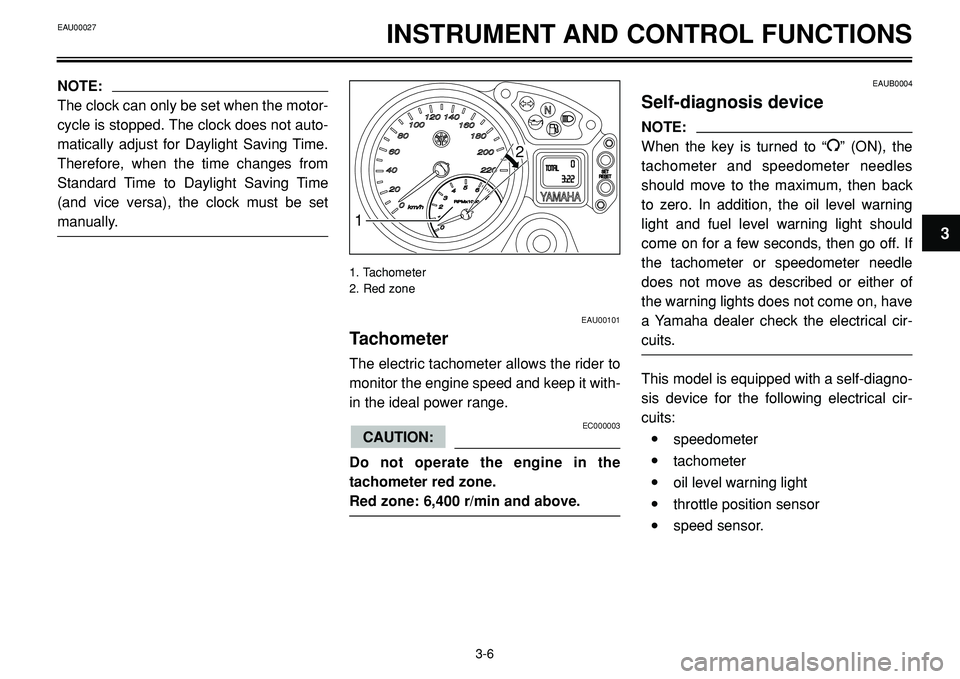
EAU00101
Tachometer
The electric tachometer allows the rider to
monitor the engine speed and keep it with-
in the ideal power range.
EC000003
Do not operate the engine in the
tachometer red zone.
Red zone: 6,400 r/min and above.
CAUTION:
EAUB0004
Self-diagnosis device
NOTE:
When the key is turned to “
I” (ON), the
tachometer and speedometer needles
should move to the maximum, then back
to zero. In addition, the oil level warning
light and fuel level warning light should
come on for a few seconds, then go off. If
the tachometer or speedometer needle
does not move as described or either of
the warning lights does not come on, have
a Yamaha dealer check the electrical cir-
cuits.
This model is equipped with a self-diagno-
sis device for the following electrical cir-
cuits:
•speedometer
•tachometer
•oil level warning light
•throttle position sensor
•speed sensor.
3-6
31
2
1. Tachometer
2. Red zone
EAU00027
Page 33 of 96
EAU01114PRE-OPERATION CHECKS
4-1
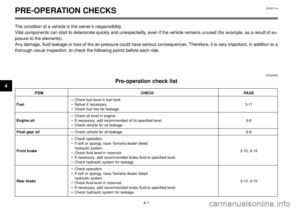
The condition of a vehicle is the owner’s responsibility.
Vital components can start to deteriorate quickly and unexpectedly, even if the vehicle remains unused (for example, as a result of ex-
posure to the elements).
Any damage, fluid leakage or loss of tire air pressure could have serious consequences. Therefore, it is very important, in addition to a
thorough visual inspection, to check the following points before each ride.
EAU03439
Pre-operation check list
ITEM CHECK PAGE
• Check fuel level in fuel tank.
Fuel• Refuel if necessary.3-11
• Check fuel line for leakage.
• Check oil level in engine.
Engine oil• If necessary, add recommended oil to specified level. 6-6
• Check vehicle for oil leakage.
Final gear oil• Check vehicle for oil leakage.6-8
• Check operation.
• If soft or spongy, have Yamaha dealer bleed
hydraulic system.
Front brake
• Check fluid level in reservoir.3-10, 6-19
• If necessary, add recommended brake fluid to specified level.
• Check hydraulic system for leakage.
• Check operation.
• If soft or spongy, have Yamaha dealer bleed
hydraulic system.
Rear brake
• Check fluid level in reservoir.3-10, 6-19
• If necessary, add recommended brake fluid to specified level.
• Check hydraulic system for leakage.
4
Page 38 of 96
OPERATION AND IMPORTANT RIDING POINTS
1
b
a
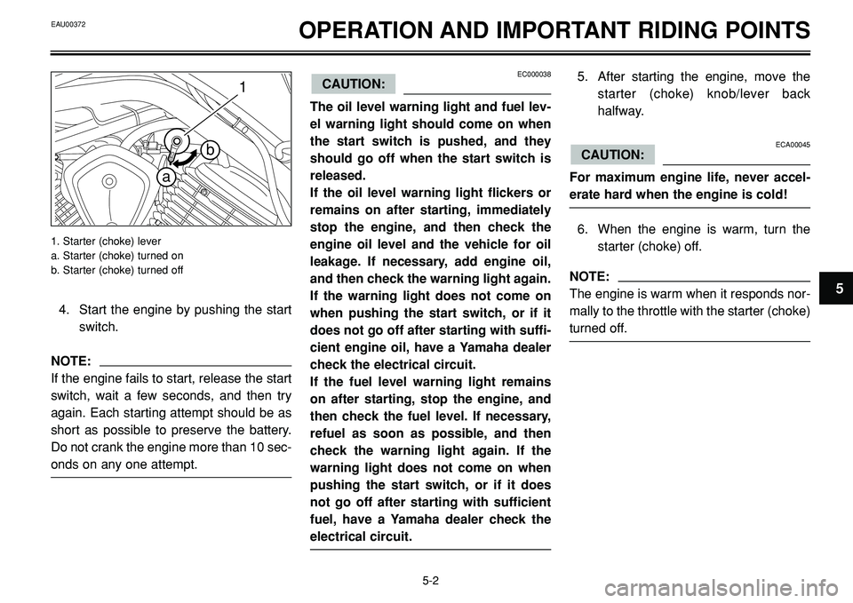
4. Start the engine by pushing the start
switch.
NOTE:
If the engine fails to start, release the start
switch, wait a few seconds, and then try
again. Each starting attempt should be as
short as possible to preserve the battery.
Do not crank the engine more than 10 sec-
onds on any one attempt.
1. Starter (choke) lever
a. Starter (choke) turned on
b. Starter (choke) turned off
EC000038
The oil level warning light and fuel lev-
el warning light should come on when
the start switch is pushed, and they
should go off when the start switch is
released.
If the oil level warning light flickers or
remains on after starting, immediately
stop the engine, and then check the
engine oil level and the vehicle for oil
leakage. If necessary, add engine oil,
and then check the warning light again.
If the warning light does not come on
when pushing the start switch, or if it
does not go off after starting with suffi-
cient engine oil, have a Yamaha dealer
check the electrical circuit.
If the fuel level warning light remains
on after starting, stop the engine, and
then check the fuel level. If necessary,
refuel as soon as possible, and then
check the warning light again. If the
warning light does not come on when
pushing the start switch, or if it does
not go off after starting with sufficient
fuel, have a Yamaha dealer check the
electrical circuit.
CAUTION:5. After starting the engine, move the
starter (choke) knob/lever back
halfway.
ECA00045
For maximum engine life, never accel-
erate hard when the engine is cold!
6. When the engine is warm, turn the
starter (choke) off.
NOTE:
The engine is warm when it responds nor-
mally to the throttle with the starter (choke)
turned off.
CAUTION:
EAU00372
5-2
5
Page 40 of 96
OPERATION AND IMPORTANT RIDING POINTS
EAU00424
Tips for reducing fuel
consumption
Fuel consumption depends largely on your
riding style. Consider the following tips to
reduce fuel consumption:
•Thoroughly warm up the engine.
•Turn the starter (choke) off as soon
as possible.
•Shift up swiftly, and avoid high engine
speeds during acceleration.
•Do not rev the engine while shifting
down, and avoid high engine speeds
with no load on the engine.
•Turn the engine off instead of letting it
idle for an extended length of time
(e.g., in traffic jams, at traffic lights or
at railroad crossings).
5-4
5
EAU00372
EAU01128
Engine break-in
There is never a more important period in
the life of your engine than the period be-
tween 0 and 1,600 km (1,000 mi). For this
reason, you should read the following ma-
terial carefully.
Since the engine is brand new, do not put
an excessive load on it for the first 1,600
km (1,000 mi). The various parts in the en-
gine wear and polish themselves to the
correct operating clearances. During this
period, prolonged full-throttle operation or
any condition that might result in engine
overheating must be avoided.
EAU01171
0-1,000 km (0-600 mi)
Avoid prolonged operation above 1/3 throt-
tle.
1,000-1,600 km (600-1,000 mi)
Avoid prolonged operation above 1/2 throt-
tle.
EC000056
After 1,000 km (600 mi) of operation,
the engine oil and final gear oil must be
changed, and the oil filter cartridge/ele-
ment replaced.
1,600 km (1,000 mi) and beyond
The vehicle can now be operated normal-
ly.
EC000049
If any engine trouble should occur dur-
ing the engine break-in period, immedi-
ately have a Yamaha dealer check the
vehicle.
CAUTION:
CAUTION:
Page 42 of 96
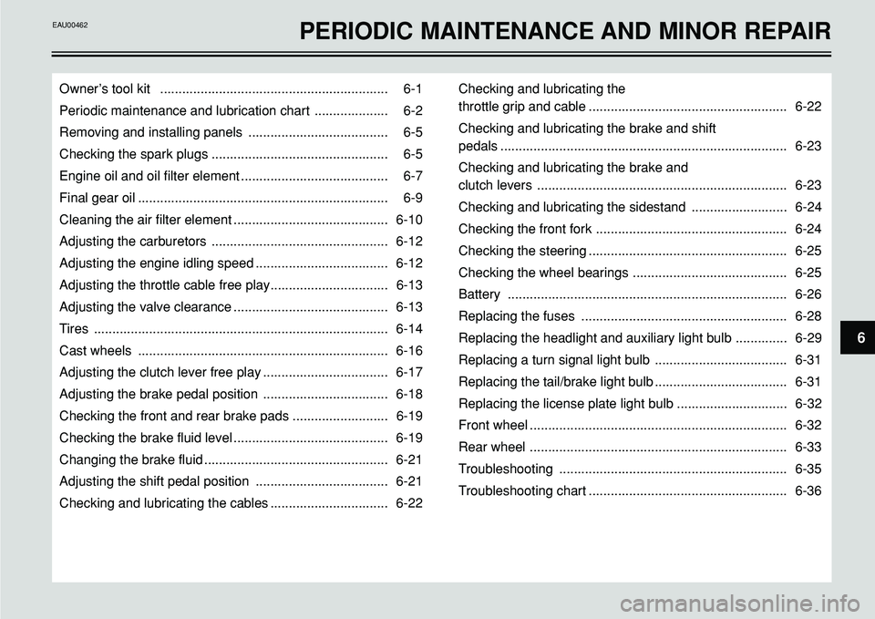
6
Owner’s tool kit .............................................................. 6-1
Periodic maintenance and lubrication chart .................... 6-2
Removing and installing panels ...................................... 6-5
Checking the spark plugs ................................................ 6-5
Engine oil and oil filter element ........................................ 6-7
Final gear oil .................................................................... 6-9
Cleaning the air filter element .......................................... 6-10
Adjusting the carburetors ................................................ 6-12
Adjusting the engine idling speed .................................... 6-12
Adjusting the throttle cable free play................................ 6-13
Adjusting the valve clearance .......................................... 6-13
Tires ................................................................................ 6-14
Cast wheels .................................................................... 6-16
Adjusting the clutch lever free play .................................. 6-17
Adjusting the brake pedal position .................................. 6-18
Checking the front and rear brake pads .......................... 6-19
Checking the brake fluid level .......................................... 6-19
Changing the brake fluid .................................................. 6-21
Adjusting the shift pedal position .................................... 6-21
Checking and lubricating the cables ................................ 6-22Checking and lubricating the
throttle grip and cable ...................................................... 6-22
Checking and lubricating the brake and shift
pedals .............................................................................. 6-23
Checking and lubricating the brake and
clutch levers .................................................................... 6-23
Checking and lubricating the sidestand .......................... 6-24
Checking the front fork .................................................... 6-24
Checking the steering ...................................................... 6-25
Checking the wheel bearings .......................................... 6-25
Battery ............................................................................ 6-26
Replacing the fuses ........................................................ 6-28
Replacing the headlight and auxiliary light bulb .............. 6-29
Replacing a turn signal light bulb .................................... 6-31
Replacing the tail/brake light bulb .................................... 6-31
Replacing the license plate light bulb .............................. 6-32
Front wheel ...................................................................... 6-32
Rear wheel ...................................................................... 6-33
Troubleshooting .............................................................. 6-35
Troubleshooting chart ...................................................... 6-36
PERIODIC MAINTENANCE AND MINOR REPAIREAU00462
Page 46 of 96
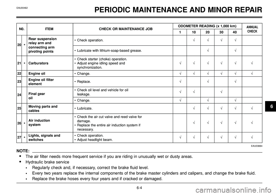
EAU00462PERIODIC MAINTENANCE AND MINOR REPAIR
EAU03884
NOTE:
•The air filter needs more frequent service if you are riding in unusually wet or dusty areas.
•Hydraulic brake service
•Regularly check and, if necessary, correct the brake fluid level.
•Every two years replace the internal components of the brake master cylinders and calipers, and change the brake fluid.
•Replace the brake hoses every four years and if cracked or damaged.
6-4
6
ODOMETER READING (x 1,000 km)ANNUALN0. ITEM CHECK OR MAINTENANCE JOB
1 10203040CHECK
Rear suspension
•Check operation. √√√√
20*relay arm and
connecting arm
•Lubricate with lithium-soap-based grease.√√
pivoting points
•Check starter (choke) operation.
21
*Carburators•Adjust engine idling speed and √√ √√ √ √synchronization.
22 Engine oil•Change.√√ √√ √ √
23Engine oil filter
•Replace. √√√
element
•Check oil level and vehicle for oil
√√ √
24Final gear
leakage.oil
•Change.√√√
25Moving parts and
•Lubricate.√√√√ √
cables
•Check the air cut valve and reed valve for
26
*Air induction
damage.
√√√√ √
system
•Replace the entire air induction system if
necessary.
27
*Lights, signals and •Check operation.
√√ √√ √ √
switches•Adjust headlight beam.