warning light YAMAHA BT1100 2004 Owners Manual
[x] Cancel search | Manufacturer: YAMAHA, Model Year: 2004, Model line: BT1100, Model: YAMAHA BT1100 2004Pages: 96, PDF Size: 3.32 MB
Page 12 of 96
22
0 20
01
80 160 14
0
12
0
1
0080
604020k
m
/
h345
6
7
2
1
0
3456721
8
DESCRIPTIONEAU00026
2-3
2
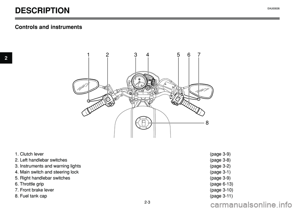
1. Clutch lever (page 3-9)
2. Left handlebar switches (page 3-8)
3. Instruments and warning lights (page 3-2)
4. Main switch and steering lock (page 3-1)
5. Right handlebar switches (page 3-9)
6. Throttle grip (page 6-13)
7. Front brake lever (page 3-10)
8. Fuel tank cap (page 3-11)
Controls and instruments
Page 13 of 96
3
Main switch/steering lock .................................................................... 3-1
Indicator and warning lights ................................................................ 3-2
Speedometer unit ................................................................................ 3-3
Tachometer ........................................................................................ 3-6
Self-diagnosis device .......................................................................... 3-6
Anti-theft alarm (optional) .................................................................... 3-8
Handlebar switches ............................................................................ 3-8
Clutch lever ........................................................................................ 3-9
Shift pedal ........................................................................................ 3-10
Brake lever ........................................................................................ 3-10
Brake pedal ...................................................................................... 3-10
Fuel tank cap .................................................................................... 3-11
Fuel .................................................................................................. 3-11
Fuel tank breather hose .................................................................... 3-12
Starter (choke) lever ........................................................................ 3-12
Seat .................................................................................................. 3-13
Helmet holders .................................................................................. 3-14
Storage compartment ...................................................................... 3-14
Adjusting the front fork ...................................................................... 3-15
Adjusting the shock absorber assembly .......................................... 3-15
Sidestand .......................................................................................... 3-16
Ignition circuit cut-off system ............................................................ 3-17
INSTRUMENT AND CONTROL FUNCTIONSEAU00027
Page 14 of 96
LOCK
POFF
ON PUSH
12
EAU00029
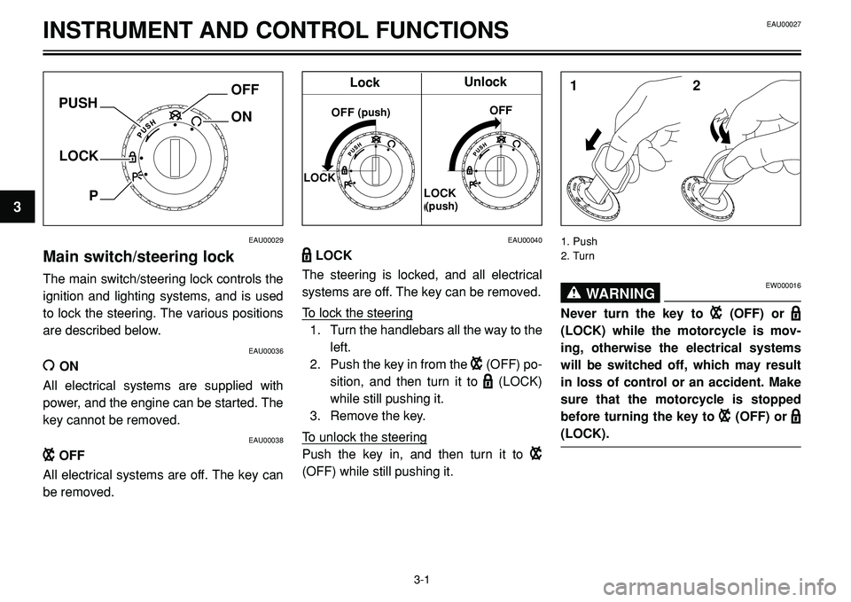
Main switch/steering lock
The main switch/steering lock controls the
ignition and lighting systems, and is used
to lock the steering. The various positions
are described below.
EAU00036
ION
All electrical systems are supplied with
power, and the engine can be started. The
key cannot be removed.
EAU00038
BOFF
All electrical systems are off. The key can
be removed.
EAU00040
DLOCK
The steering is locked, and all electrical
systems are off. The key can be removed.
To lock the steering
1. Turn the handlebars all the way to the
left.
2. Push the key in from the
B(OFF) po-
sition, and then turn it to
D(LOCK)
while still pushing it.
3. Remove the key.
To unlock the steering
Push the key in, and then turn it to
B
(OFF) while still pushing it.
1. Push
2. Turn
EAU00027
3-1
3
INSTRUMENT AND CONTROL FUNCTIONS
EW000016WARNING0
Never turn the key to B(OFF) or D
(LOCK) while the motorcycle is mov-
ing, otherwise the electrical systems
will be switched off, which may result
in loss of control or an accident. Make
sure that the motorcycle is stopped
before turning the key to
B(OFF) orD
(LOCK).
LOCKOFF (Premere)
Bloccare Sbloccare
LOCK
(Premere)OFF
Lock
(push)
Unlock
(push)
Page 15 of 96
INSTRUMENT AND CONTROL FUNCTIONS
220 200 180 160 140 120
100
80
60
40
20
km/h345
6
7
2
1
0
N
34 512EAU01590
F(Parking)
The steering is locked, and the taillight and
auxiliary light are on, but all other electrical
systems are off. The key can be removed.
The steering must be locked before the
key can be turned to “
F”.
ECA00043
Do not use the parking position for an
extended length of time, otherwise the
battery may discharge.
CAUTION:
EAU03034
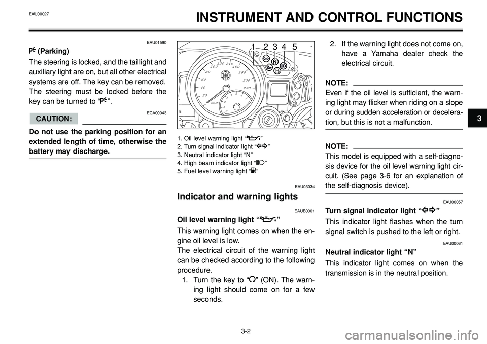
Indicator and warning lights
EAUB0001
Oil level warning light “v”
This warning light comes on when the en-
gine oil level is low.
The electrical circuit of the warning light
can be checked according to the following
procedure.
1. Turn the key to “
I” (ON). The warn-
ing light should come on for a few
seconds.
1. Oil level warning light “v”
2. Turn signal indicator light “y
y”
3. Neutral indicator light “N”
4. High beam indicator light “
1”
5. Fuel level warning light “K”
2. If the warning light does not come on,
have a Yamaha dealer check the
electrical circuit.
NOTE:
Even if the oil level is sufficient, the warn-
ing light may flicker when riding on a slope
or during sudden acceleration or decelera-
tion, but this is not a malfunction.
NOTE:
This model is equipped with a self-diagno-
sis device for the oil level warning light cir-
cuit. (See page 3-6 for an explanation of
the self-diagnosis device).
EAU00057
Turn signal indicator light “y
y”
This indicator light flashes when the turn
signal switch is pushed to the left or right.
EAU00061
Neutral indicator light “N”
This indicator light comes on when the
transmission is in the neutral position.
3-2
3
EAU00027
Page 16 of 96
INSTRUMENT AND CONTROL FUNCTIONS
2
1
54 3
1
2
6 5 4
3
EAU00063
High beam indicator light “1”
This indicator light comes on when the
high beam of the headlight is switched on.
EAUB0002
Fuel level warning light “K”
This warning light comes on when the fuel
level drops below approximately 5.8 L.
When this occurs, refuel as soon as possi-
ble.
The electrical circuit of the warning light
can be checked according to the following
procedure.
1. Turn the key to “
I” (ON).
2. If the warning light does not come on,
have a Yamaha dealer check the
electrical circuit.
NOTE:
This model is equipped with a self-diagno-
sis device for the fuel level warning light
circuit. (See page 3-6 for an explanation of
the self-diagnosis device).
EAUB0003
Speedometer unit
The speedometer unit is equipped with the
following:
•a speedometer (which shows riding
speed)
•a tachometer (which shows engine
r/min)
•an odometer (which shows the total
distance traveled)
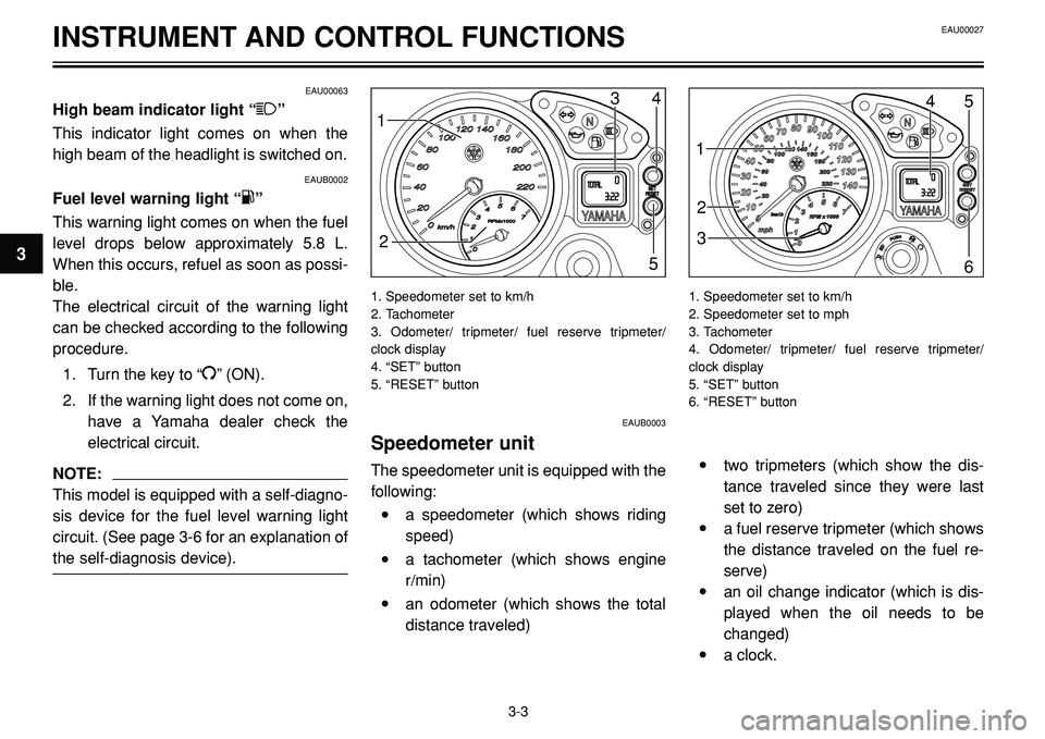
1. Speedometer set to km/h
2. Tachometer
3. Odometer/ tripmeter/ fuel reserve tripmeter/
clock display
4. “SET” button
5. “RESET” button
•two tripmeters (which show the dis-
tance traveled since they were last
set to zero)
•a fuel reserve tripmeter (which shows
the distance traveled on the fuel re-
serve)
•an oil change indicator (which is dis-
played when the oil needs to be
changed)
•a clock.
1. Speedometer set to km/h
2. Speedometer set to mph
3. Tachometer
4. Odometer/ tripmeter/ fuel reserve tripmeter/
clock display
5. “SET” button
6. “RESET” button
EAU00027
3-3
3
Page 17 of 96
INSTRUMENT AND CONTROL FUNCTIONS
NOTE:
Depending on the market where the
motorcycle is sold, the speedometer can
be set to either mph or km/h. When the
speedometer is set to mph, the odometer
counts in miles (1 mile = 1.61 km).Odometer and tripmeter modes
Pushing the “SET” button switches the dis-
play between the odometer mode “ODO”
and the tripmeter modes “TRIP 1” and
“TRIP 2” in the following order: ODO 6
TRIP 1 6TRIP 2 6ODO
When the fuel warning light comes on, the
display will automatically change to the fu-
el reserve tripmeter mode “TRIP F” and
start counting the distance traveled from
that point. In that case, pushing the “SET”
button switches the display between the
various tripmeter and odometer modes in
the following order: TRIP F 6TRIP 1 6
TRIP 2 6ODO 6TRIP F
To reset a tripmeter, select it by pushing
the “SET” button, and then push the “RE-
SET” button for at least one second. If you
do not reset the fuel reserve tripmeter
manually, it will reset itself automatically
and the display will return to the prior
mode after refueling and traveling several
kilometers.Oil change indicator
At the initial 1,000 km (620 mi) and every
10,000 km (6,200 mi) thereafter, the mes-
sage “OIL CHANGE” appears in the dis-
play for a few seconds when the key is
turned to “ON”, to indicate that the engine
oil should be changed.
After changing the engine oil, reset the oil
change indicator.
If the engine oil is changed before the oil
change indicator appears in the display
(i.e. before the periodic oil change interval
has been reached), the indicator must be
reset after the oil change for the next peri-
odic oil change to be indicated at the cor-
rect time.
NOTE:
When the message “OIL CHANGE”
appears in the display, be sure to change
the engine oil as soon as possible. In addi-
tion to these kilometer-based oil changes,
be sure to have a Yamaha dealer perform
the annual checks specified in the period-
ic maintenance and lubrication chart on
page 6-2.
EAU00027
3-4
3
Page 19 of 96
INSTRUMENT AND CONTROL FUNCTIONS
NOTE:
The clock can only be set when the motor-
cycle is stopped. The clock does not auto-
matically adjust for Daylight Saving Time.
Therefore, when the time changes from
Standard Time to Daylight Saving Time
(and vice versa), the clock must be set
manually.
EAU00101
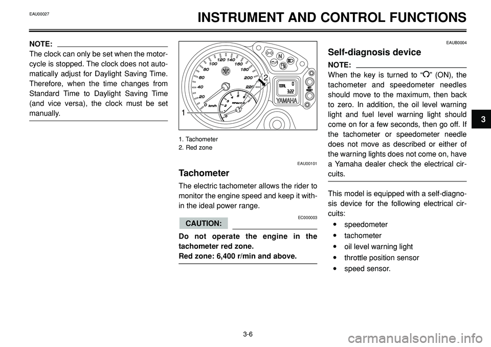
Tachometer
The electric tachometer allows the rider to
monitor the engine speed and keep it with-
in the ideal power range.
EC000003
Do not operate the engine in the
tachometer red zone.
Red zone: 6,400 r/min and above.
CAUTION:
EAUB0004
Self-diagnosis device
NOTE:
When the key is turned to “
I” (ON), the
tachometer and speedometer needles
should move to the maximum, then back
to zero. In addition, the oil level warning
light and fuel level warning light should
come on for a few seconds, then go off. If
the tachometer or speedometer needle
does not move as described or either of
the warning lights does not come on, have
a Yamaha dealer check the electrical cir-
cuits.
This model is equipped with a self-diagno-
sis device for the following electrical cir-
cuits:
•speedometer
•tachometer
•oil level warning light
•throttle position sensor
•speed sensor.
3-6
31
2
1. Tachometer
2. Red zone
EAU00027
Page 37 of 96
OPERATION AND IMPORTANT RIDING POINTS
EAU00373WARNING0
•Become thoroughly familiar with
all operating controls and their
functions before riding. Consult a
Yamaha dealer regarding any con-
trol or function that you do not
thoroughly understand.
•Never start the engine or operate it
in a closed area for any length of
time. Exhaust fumes are poiso-
nous, and inhaling them can cause
loss of consciousness and death
within a short time. Always make
sure that there is adequate ventila-
tion.
•Before starting out, make sure that
the sidestand is up. If the side-
stand is not raised completely, it
could contact the ground and dis-
tract the operator, resulting in a
possible loss of control.
EAU03818
Starting the engine
In order for the ignition circuit cut-off sys-
tem to enable starting, one of the following
conditions must be met:
•The transmission is in the neutral po-
sition.
•The transmission is in gear with the
clutch lever pulled and the sidestand
up.
EW000054WARNING0
•Before starting the engine, check
the function of the ignition circuit
cut-off system according to the
procedure described on page 3-18.
•Never ride with the sidestand
down.
1. Turn the key to “I” (ON) and make
sure that the engine stop switch is set
to “
I”.
EC000035
If the fuel level warning light comes on,
check the fuel level, and, if necessary,
refuel as soon as possible.
2. Shift the transmission into the neutral
position.
When the transmission is in the neu-
tral position, the neutral indicator light
should be on, otherwise have a
Yamaha dealer check the electrical
circuit.
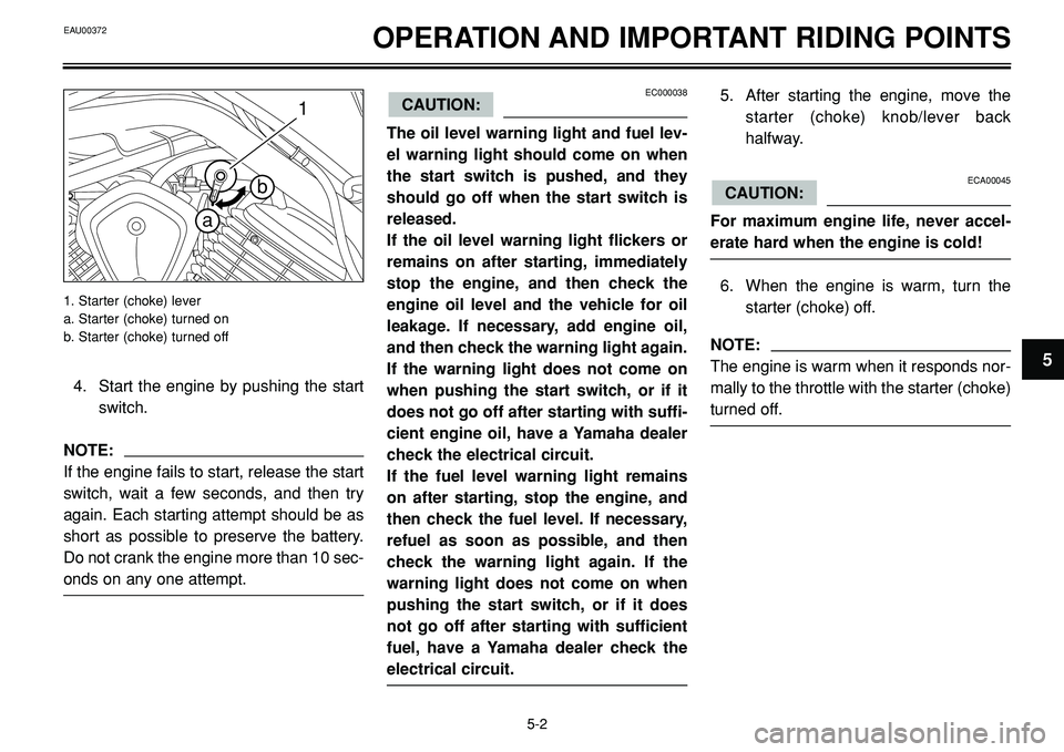
3. Turn the starter (choke) on and com-
pletely close the throttle. (See page
3-12 for starter (choke) operation).
CAUTION:
5-1
5
EAU00372
Page 38 of 96
OPERATION AND IMPORTANT RIDING POINTS
1
b
a
4. Start the engine by pushing the start
switch.
NOTE:
If the engine fails to start, release the start
switch, wait a few seconds, and then try
again. Each starting attempt should be as
short as possible to preserve the battery.
Do not crank the engine more than 10 sec-
onds on any one attempt.
1. Starter (choke) lever
a. Starter (choke) turned on
b. Starter (choke) turned off
EC000038
The oil level warning light and fuel lev-
el warning light should come on when
the start switch is pushed, and they
should go off when the start switch is
released.
If the oil level warning light flickers or
remains on after starting, immediately
stop the engine, and then check the
engine oil level and the vehicle for oil
leakage. If necessary, add engine oil,
and then check the warning light again.
If the warning light does not come on
when pushing the start switch, or if it
does not go off after starting with suffi-
cient engine oil, have a Yamaha dealer
check the electrical circuit.
If the fuel level warning light remains
on after starting, stop the engine, and
then check the fuel level. If necessary,
refuel as soon as possible, and then
check the warning light again. If the
warning light does not come on when
pushing the start switch, or if it does
not go off after starting with sufficient
fuel, have a Yamaha dealer check the
electrical circuit.
CAUTION:5. After starting the engine, move the
starter (choke) knob/lever back
halfway.
ECA00045
For maximum engine life, never accel-
erate hard when the engine is cold!
6. When the engine is warm, turn the
starter (choke) off.
NOTE:
The engine is warm when it responds nor-
mally to the throttle with the starter (choke)
turned off.
CAUTION:
EAU00372
5-2
5
Page 50 of 96
EAU00462PERIODIC MAINTENANCE AND MINOR REPAIR
EC000072
•In order to prevent clutch slippage
(since the engine oil also lubri-
cates the clutch), do not mix any
chemical additives with the oil or
use oils of a higher grade than
“CD”. In addition, do not use oils
labeled "ENERGY CONSERVING II"
or higher.
•Make sure that no foreign material
enters the crankcase.
CAUTION:6. Start the engine, and then let it idle for
several minutes while checking it for
oil leakage. If oil is leaking, immedi-
ately turn the engine off and check for
the cause.
NOTE:
After the engine is started, the engine oil
level warning light should go off if the oil
level is sufficient.
EC000067
If the oil level warning light flickers or
remains on, immediately turn the
engine off and have a Yamaha dealer
check the vehicle.
7. Turn the engine off, and then check
the oil level and correct it if neces-
sary.
NOTE:
Have a Yamaha dealer replace the oil filter
element when necessary.
CAUTION:
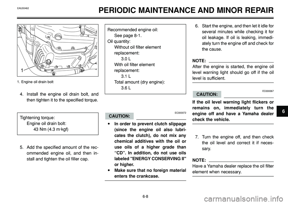
1. Engine oil drain bolt
6-8
6
1
4. Install the engine oil drain bolt, and
then tighten it to the specified torque.
5. Add the specified amount of the rec-
ommended engine oil, and then in-
stall and tighten the oil filler cap. Tightening torque:
Engine oil drain bolt:
43 Nm (4.3 m·kgf)
Recommended engine oil:
See page 8-1.
Oil quantity:
Without oil filter element
replacement:
3.0 L
With oil filter element
replacement:
3.1 L
Total amount (dry engine):
3.6 L