ignition YAMAHA CYGNUS 125 2000 Owners Manual
[x] Cancel search | Manufacturer: YAMAHA, Model Year: 2000, Model line: CYGNUS 125, Model: YAMAHA CYGNUS 125 2000Pages: 76, PDF Size: 1.3 MB
Page 17 of 76
3-1
1
2
3
4
5
6
7
8
9
INSTRUMENT AND CONTROL FUNCTIONS
EAU10460
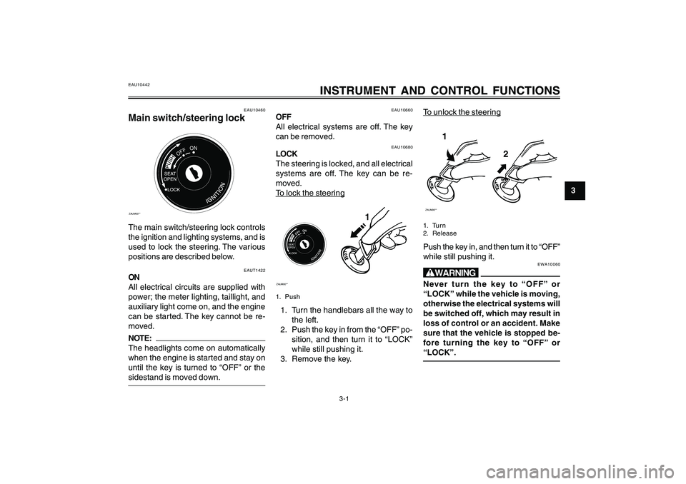
Main switch/steering lockZAUM00**
OFFON
The main switch/steering lock controls
the ignition and lighting systems, and is
used to lock the steering. The various
positions are described below.
EAU10660
OFF
All electrical systems are off. The key
can be removed.
EAU10442
INSTRUMENT AND CONTROL FUNCTIONS
EAUT1422
ON
All electrical circuits are supplied with
power; the meter lighting, taillight, and
auxiliary light come on, and the engine
can be started. The key cannot be re-
moved.NOTE:
The headlights come on automatically
when the engine is started and stay on
until the key is turned to “OFF” or the
sidestand is moved down.
EAU10680
LOCK
The steering is locked, and all electrical
systems are off. The key can be re-
moved.To loc
k the steer
ing
ZAUM00**
OFFON
1
1. Push1. Turn the handlebars all the way to
the left.
2. Push the key in from the “OFF” po-
sition, and then turn it to “LOCK”
while still pushing it.
3. Remove the key.
To unloc
k the steer
ing
1
2
ZAUM00**1. Tur n
2. ReleasePush the key in, and then turn it to “OFF”
while still pushing it.
EWA10060
wNever turn the key to “OFF” or
“LOCK” while the vehicle is moving,
otherwise the electrical systems will
be switched off, which may result in
loss of control or an accident. Make
sure that the vehicle is stopped be-
fore turning the key to “OFF” or
“LOCK”.
5ML-F8199-E0ch3re.pmd2003/12/12, 16:03 1
Page 26 of 76
3-10
1
2
3
4
5
6
7
8
9
INSTRUMENT AND CONTROL FUNCTIONS
EAU15300
SidestandThe sidestand is located on the left side
of the frame. Raise the sidestand or lower
it with your foot while holding the motor-
cycle upright.NOTE:
The built-in sidestand switch is part of
the ignition circuit cut-off system, which
cuts the ignition in certain situations.
(See further down for an explanation of
the ignition circuit cut-off system.)
EWA10240
wThe vehicle must not be ridden with
the sidestand down, or if the
sidestand cannot be properly moved
up (or does not stay up), otherwise
the sidestand could contact the
ground and distract the operator, re-
sulting in a possible loss of control.
Yamaha’s ignition circuit cut-off sys-
tem has been designed to assist the
operator in fulfilling the responsibil-
ity of raising the sidestand before
starting off. Therefore, check this sys-
tem regularly as described below andhave a Yamaha dealer repair it if it
does not function properly.
EAUT1091
Sidestand switch operation
checkCheck the operation of the sidestand
switch against the information below.
EWA10260
w8 88 8
8The vehicle must be placed on
the centerstand during this in-
spection.
8 88 8
8If a malfunction is noted, have a
Yamaha dealer check the system
before riding.
5ML-F8199-E0ch3re.pmd2003/12/12, 16:03 10
Page 30 of 76
4-3
1
2
3
4
5
6
7
8
9
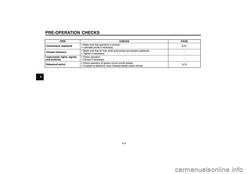
PRE-OPERATION CHECKSCenterstand, sidestand Make sure that operation is smooth.
Lubricate pivots if necessary.6-21
Chassis fasteners Make sure that all nuts, bolts and screws are properly tightened.
Tighten if necessary.-
Instruments, lights, signals
and switches Check operation.
Correct if necessary.-
Sidestand switch Check operation of ignition circuit cut-off system.
If system is defective, have Yamaha dealer check vehicle.3-10 ITEM CHECKS PAGE
5ML-F8199-E0ch4.pmd2003/12/12, 16:03 3
Page 59 of 76

6-25
1
2
3
4
5
6
7
8
9
PERIODIC MAINTENANCE AND MINOR REPAIR
ZAUM00**
1
1. BatteryTo install the battery
1. Connect the battery couplers, and
then place the battery in the origi-
nal position.
2. Install the battery holder bracket by
installing the bolt.
3. Install the panel by installing the
screw.
4. Fully charge the battery before in-
stallation.
EAUT1431
Replacing the fusesThe main fuse box is located behind
panel B. (See page 6-6.)ZAUM00**
1
1. Main fuseThe fuse block, which contains the fuses
for the individual circuits, is located in
the storage compartment. (See page 3-
8.)
ZAUM00**
1
2
3
4
5
6
1. Lid
2. Fuse box
3. Carburetor heater fuse
4. Ignition fuse
5. Headlight fuse
6. Signaling system fuseIf a fuse is blown, replace it as follows.
1. Turn the key to “OFF” and turn off
the electrical circuit in question.
2. Remove the blown fuse, and then
install a new fuse of the specified
amperage.
5ML-F8199-E0ch6re.pmd2003/12/12, 16:04 25
Page 60 of 76

6-26
1
2
3
4
5
6
7
8
9
PERIODIC MAINTENANCE AND MINOR REPAIR
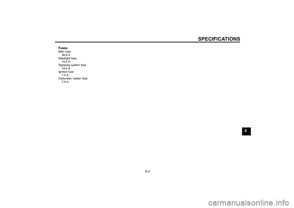
Specified fuses:
Main fuse:
30 A
Headlight fuse:
15 A
Signaling system fuse:
15 A
Ignition fuse:
7.5 A
Carburetor heater fuse:
7.5 A
ECA10640
cCDo not use a fuse of a higher amper-
age rating than recommended to
avoid causing extensive damage to
the electrical system and possibly a
fire.3. Turn the key to “ON” and turn on
the electrical circuit in question to
check if the device operates.
4. If the fuse immediately blows again,
have a Yamaha dealer check the
electrical system.
EAU23710
Replacing a headlight bulbThis model is equipped with quartz bulb
headlights. If a headlight bulb burns out,
replace it as follows.
1. Place the vehicle on the
centerstand.
2. Remove panel B. (See page 6-6.)
3. Disconnect the headlight coupler,
and then remove the bulb cover.ZAUM00**
1
1. Bulb cover4. Unhook the headlight bulb holder,
and then remove the defective bulb.
ZAUM00**
1
1. Headlight bulb holder
EWA10790
wHeadlight bulbs get very hot. There-
fore, keep flammable products away
from a lit headlight bulb, and do not
touch the bulb until it has cooled
down.5. Place a new headlight bulb into po-
sition, and then secure it with the
bulb holder.
ECA10660
cCDo not touch the glass part of the
headlight bulb to keep it free from oil,
otherwise the transparency of the
glass, the luminosity of the bulb, and
5ML-F8199-E0ch6re.pmd2003/12/12, 16:04 26
Page 63 of 76

6-29
1
2
3
4
5
6
7
8
9
PERIODIC MAINTENANCE AND MINOR REPAIR
EAU25860
TroubleshootingAlthough Yamaha scooters receive a
thorough inspection before shipment
from the factory, trouble may occur dur-
ing operation. Any problem in the fuel,
compression, or ignition systems, for
example, can cause poor starting and
loss of power.
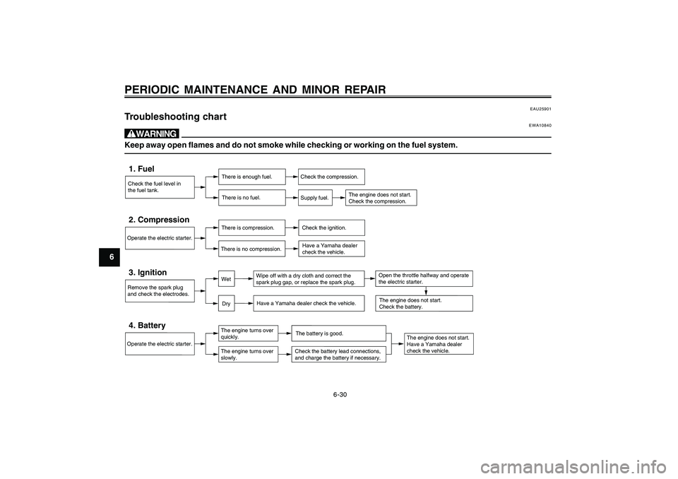
The following troubleshooting chart rep-
resents a quick and easy procedure for
checking these vital systems yourself.
However, should your scooter require any
repair, take it to a Yamaha dealer, whose
skilled technicians have the necessary
tools, experience, and know-how to ser-
vice the scooter properly.
Use only genuine Yamaha replacement
parts. Imitation parts may look like
Yamaha parts, but they are often infe-
rior, have a shorter service life and can
lead to expensive repair bills.
5ML-F8199-E0ch6re.pmd2003/12/12, 16:04 29
Page 64 of 76
6-30
1
2
3
4
5
6
7
8
9
PERIODIC MAINTENANCE AND MINOR REPAIR
EAU25901
Troubleshooting chart
EWA10840
wKeep away open flames and do not smoke while checking or working on the fuel system.Check the fuel level in
the fuel tank.1. Fuel
There is enough fuel.
There is no fuel.
Check the compression.
Supply fuel.
The engine does not start.
Check the compression.
Operate the electric starter.2. Compression
There is compression.
There is no compression.
Check the ignition.
Have a Yamaha dealer
check the vehicle.
Remove the spark plug
and check the electrodes.3. Ignition
Wipe off with a dry cloth and correct the
spark plug gap, or replace the spark plug.
Have a Yamaha dealer check the vehicle.
The engine does not start.
Have a Yamaha dealer
check the vehicle.
The engine does not start.
Check the battery.
Operate the electric starter.4. Battery
The engine turns over
quickly.
The engine turns over
slowly.
The battery is good.Check the battery lead connections,
and charge the battery if necessary.
DryWet
Open the throttle halfway and operate
the electric starter.
5ML-F8199-E0ch6re.pmd2003/12/12, 16:04 30
Page 70 of 76
8-2
1
2
3
4
5
6
7
8
9
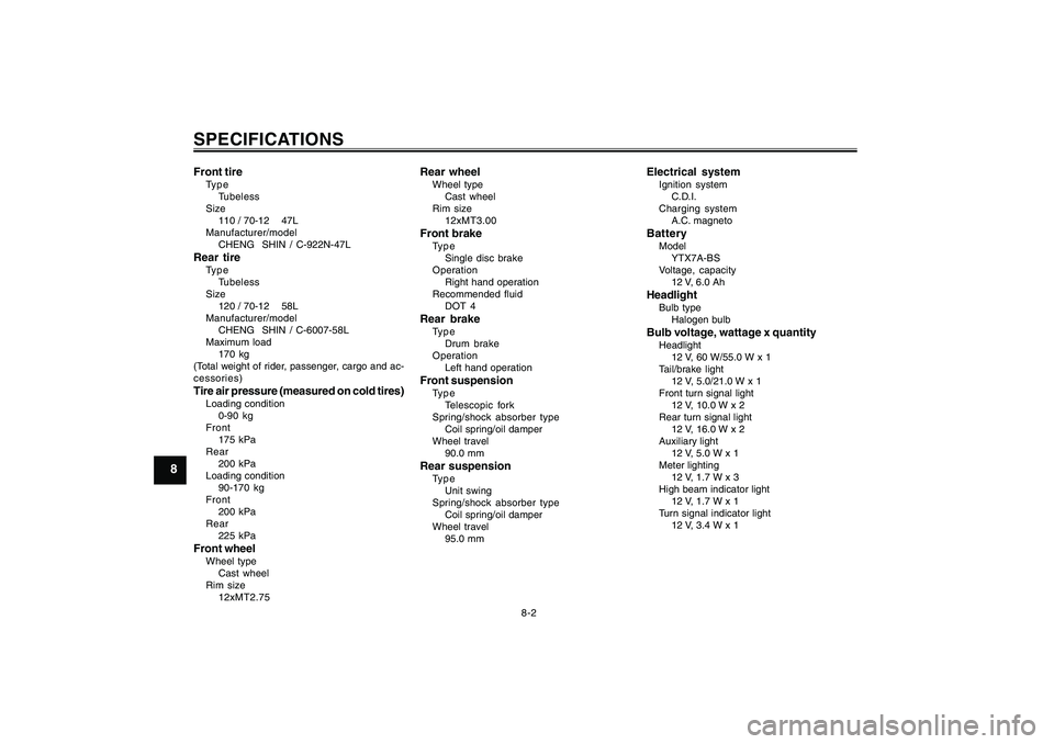
SPECIFICATIONSFront tireType
Tubeless
Size
110 / 70-12 47L
Manufacturer/model
CHENG SHIN / C-922N-47LRear tireType
Tubeless
Size
120 / 70-12 58L
Manufacturer/model
CHENG SHIN / C-6007-58L
Maximum load
170 kg
(Total weight of rider, passenger, cargo and ac-
cessories)Tire air pressure (measured on cold tires)Loading condition
0-90 kg
Front
175 kPa
Rear
200 kPa
Loading condition
90-170 kg
Front
200 kPa
Rear
225 kPaFront wheelWheel type
Cast wheel
Rim size
12xMT2.75
Rear wheelWheel type
Cast wheel
Rim size
12xMT3.00Front brakeType
Single disc brake
Operation
Right hand operation
Recommended fluid
DOT 4Rear brakeType
Drum brake
Operation
Left hand operationFront suspensionType
Telescopic fork
Spring/shock absorber type
Coil spring/oil damper
Wheel travel
90.0 mmRear suspensionType
Unit swing
Spring/shock absorber type
Coil spring/oil damper
Wheel travel
95.0 mm
Electrical systemIgnition system
C.D.I.
Charging system
A.C. magnetoBatteryModel
YTX7A-BS
Voltage, capacity
12 V, 6.0 AhHeadlightBulb type
Halogen bulbBulb voltage, wattage x quantityHeadlight
12 V, 60 W/55.0 W x 1
Tail/brake light
12 V, 5.0/21.0 W x 1
Front turn signal light
12 V, 10.0 W x 2
Rear turn signal light
12 V, 16.0 W x 2
Auxiliary light
12 V, 5.0 W x 1
Meter lighting
12 V, 1.7 W x 3
High beam indicator light
12 V, 1.7 W x 1
Turn signal indicator light
12 V, 3.4 W x 1
5ML-F8199-E0ch8re.pmd2003/12/12, 16:04 2
Page 71 of 76
8-3
1
2
3
4
5
6
7
8
9
SPECIFICATIONS
FusesMain fuse
30.0 A
Headlight fuse
15.0 A
Signaling system fuse
15.0 A
Ignition fuse
7.5 A
Carburetor heater fuse
7.5 A
5ML-F8199-E0ch8re.pmd2003/12/12, 16:04 3