horn YAMAHA FJR1300A 2004 Owners Manual
[x] Cancel search | Manufacturer: YAMAHA, Model Year: 2004, Model line: FJR1300A, Model: YAMAHA FJR1300A 2004Pages: 90, PDF Size: 6.9 MB
Page 22 of 90

INSTRUMENT AND CONTROL FUNCTIONS
3-8
3
EAU12342
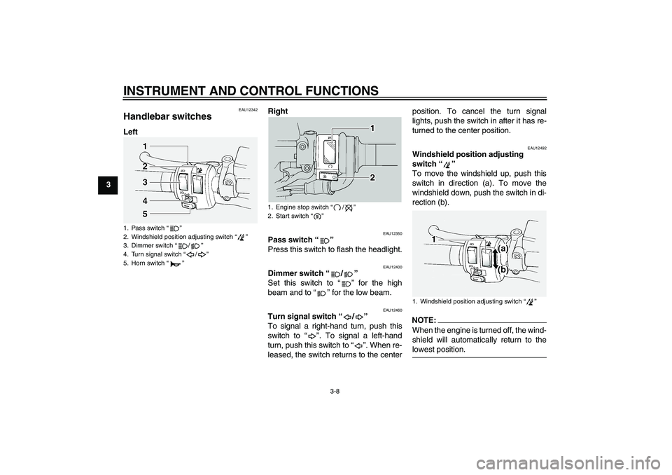
Handlebar switches LeftRight
EAU12350
Pass switch “”
Press this switch to flash the headlight.
EAU12400
Dimmer switch “/”
Set this switch to “” for the high
beam and to “” for the low beam.
EAU12460
Turn signal switch “/”
To signal a right-hand turn, push this
switch to “”. To signal a left-hand
turn, push this switch to “”. When re-
leased, the switch returns to the centerposition. To cancel the turn signal
lights, push the switch in after it has re-
turned to the center position.
EAU12492
Windshield position adjusting
switch “”
To move the windshield up, push this
switch in direction (a). To move the
windshield down, push the switch in di-
rection (b).NOTE:When the engine is turned off, the wind-
shield will automatically return to thelowest position.
1. Pass switch “”
2. Windshield position adjusting switch “”
3. Dimmer switch “/”
4. Turn signal switch “/”
5. Horn switch “”
1. Engine stop switch “/”
2. Start switch “”
1. Windshield position adjusting switch “”
5JWE3.book Page 8 Friday, September 5, 2003 3:08 PM
Page 23 of 90

INSTRUMENT AND CONTROL FUNCTIONS
3-9
3
EAU12500
Horn switch “”
Press this switch to sound the horn.
EAU12660
Engine stop switch “/”
Set this switch to “” before starting
the engine. Set this switch to “” to
stop the engine in case of an emergen-
cy, such as when the vehicle overturns
or when the throttle cable is stuck.
EAU12710
Start switch “”
Push this switch to crank the engine
with the starter.CAUTION:
ECA10050
See page 5-1 for starting instruc-tions prior to starting the engine.
EAU12731
Hazard switch “”
With the key in the “ON” or “” posi-
tion, use this switch to turn on the haz-
ard light (simultaneous flashing of all
turn signal lights).
The hazard light is used in case of an
emergency or to warn other drivers
when your vehicle is stopped where it
might be a traffic hazard.CAUTION:
ECA10060
Do not use the hazard light for an ex-
tended length of time, otherwise thebattery may discharge.
EAU12830
Clutch lever The clutch lever is located at the left
handlebar grip. To disengage the
clutch, pull the lever toward the handle-
bar grip. To engage the clutch, release
the lever. The lever should be pulled
rapidly and released slowly for smooth
clutch operation.
The clutch lever is equipped with a
clutch lever position adjusting dial. To
adjust the distance between the clutch
lever and the handlebar grip, turn the
adjusting dial while holding the lever
pushed away from the handlebar grip.
1. Hazard switch “”
1. Clutch lever
2. Arrow mark
3. Clutch lever position adjusting dial
4. Distance between clutch lever and handlebar
grip
5JWE3.book Page 9 Friday, September 5, 2003 3:08 PM
Page 86 of 90

INDEXAABS (For FJR1300A only) .................... 3-11
ABS warning light
(For FJR1300A only) ............................ 3-4
Accessory box....................................... 3-15
Air filter element, cleaning..................... 6-13
Anti-theft alarm (optional)........................ 3-7
Auxiliary light bulb, replacing ................ 6-31BBattery................................................... 6-27
Brake and clutch fluid levels,
checking ............................................. 6-20
Brake and clutch fluids, changing ......... 6-22
Brake and clutch levers, checking
and lubricating .................................... 6-23
Brake and shift pedals, checking
and lubricating .................................... 6-23
Brake lever ............................................ 3-10
Brake pedal ........................................... 3-11
Brake pedal position, adjusting ............. 6-19CCables, checking and lubricating .......... 6-22
Care ........................................................ 7-1
Catalytic converter ................................ 3-14
Centerstand and sidestand,
checking and lubricating ..................... 6-24
Clutch lever ............................................. 3-9
Clutch lever free play ............................ 6-18
Coolant.................................................. 6-11DDimmer switch ........................................ 3-8EEngine break-in ....................................... 5-3
Engine idling speed, checking .............. 6-14Engine oil and oil filter cartridge ............. 6-8
Engine stop switch.................................. 3-9
Engine trouble warning light ................... 3-4
FFinal gear oil ......................................... 6-10
Front and rear brake pads, checking .... 6-20
Front fork, adjusting .............................. 3-16
Front fork, checking .............................. 6-25
Fuel....................................................... 3-12
Fuel consumption, tips for reducing........ 5-3
Fuel tank breather hose........................ 3-13
Fuel tank cap ........................................ 3-12
Fuses, replacing ................................... 6-28HHandlebar switches ................................ 3-8
Hazard switch ......................................... 3-9
Headlight bulb, replacing ...................... 6-30
High beam indicator light ........................ 3-4
Horn switch ............................................. 3-9IIdentification numbers ............................ 9-1
Ignition circuit cut-off system ................ 3-20
Immobilizer system ................................. 3-1
Immobilizer system indicator light........... 3-4
Indicator and warning lights .................... 3-3KKey identification number ....................... 9-1LLocks for optional side cases and
travel trunk ......................................... 3-19MMain switch/steering lock........................ 3-2
Model label ............................................. 9-2
Multi-function display .............................. 3-6
NNeutral indicator light .............................. 3-4OOil level warning light .............................. 3-4PPanels, removing and installing .............. 6-5
Parking .................................................... 5-4
Part locations .......................................... 2-1
Pass switch ............................................. 3-8
Periodic maintenance and
lubrication chart .................................... 6-2
Pre-operation check list........................... 4-2RRear brake light switch, adjusting ......... 6-19
Rear suspension, lubricating ................. 6-25SSafety information ................................... 1-1
Seats ..................................................... 3-14
Shifting .................................................... 5-2
Shift pedal ............................................. 3-10
Shock absorber assembly, adjusting .... 3-18
Sidestand .............................................. 3-19
Spark plugs, checking ............................. 6-7
Specifications .......................................... 8-1
Speedometer........................................... 3-5
Starting the engine .................................. 5-1
Start switch.............................................. 3-9
Steering, checking................................. 6-26
Storage.................................................... 7-3
Storage compartment............................ 3-15
Swingarm pivots, lubricating ................. 6-24TTachometer ............................................. 3-5
Throttle cable free play, adjusting ......... 6-15
5JWE3.book Page 1 Friday, September 5, 2003 3:08 PM