warning YAMAHA FJR1300A 2018 Owner's Manual
[x] Cancel search | Manufacturer: YAMAHA, Model Year: 2018, Model line: FJR1300A, Model: YAMAHA FJR1300A 2018Pages: 118, PDF Size: 3.5 MB
Page 56 of 118
Instrument and control functions
3-42
3
TIP
Although the total number of
clicks of a damping force adjust-
ing mechanism may not exactly
match the above specifications
due to small differences in pro-
duction, the actual number of
clicks always represents the entire
adjusting range. To obtain a pre-
cise adjustment, check the num-
ber of clicks and modify the
minimum and standard specifica-
tions as necessary.
When turning the damping force
adjusting knob in direction (a), the
0 click position and the 1 click po-
sition may be the same.
NOTICE
ECA16571
To avoi d d amag ing the mechanism,
d o not attempt to move beyon d the
maximum or minimum settin gs.
WARNING
EWA10222
This shock a bsor ber assem bly con-
tains hi ghly pressurize d nitro gen
g as. Rea d an d un derstan d the fol-
lowin g information before han dlin g
the shock a bsor ber assem bly.
Do not tamper with or attempt
to open the cylind er assembly.
Do not su bject the shock a b-
sor ber assem bly to an open
flame or other hi gh heat source.
This may cause the unit to ex-
plo de due to excessive g as
pressure.
Do not deform or damag e the
cylin der in any way. Cylin der
d amag e will result in poor
d ampin g performance.
Do not d ispose of a damag ed or
worn-out shock a bsor ber as-
sem bl
y yourself. Take the shock
a b sor ber assem bly to a Yamaha
d ealer for any service.
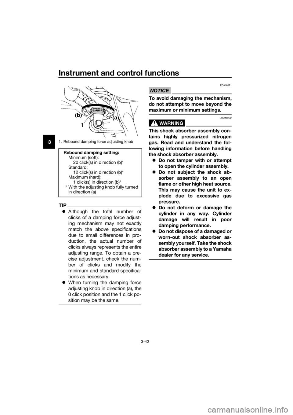
1. Rebound damping force adjusting knob
Re boun d d ampin g setting :
Minimum (soft): 20 click(s) in direction (b)*
Standard: 12 click(s) in direction (b)*
Maximum (hard):
1 click(s) in direction (b)*
* With the adjusting knob fully turned in direction (a)
UB88E1E0.book Page 42 Monday, July 10, 2017 2:46 PM
Page 57 of 118
Instrument and control functions
3-43
3
EAU15306
Si destan d
The sidestand is located on the left
side of the frame. Raise the sidestand
or lower it with your foot while holding
the vehicle upright.
TIP
The built-in sidestand switch is part of
the ignition circuit cut-off system,
which cuts the ignition in certain situa-
tions. (See the following section for an
explanation of the ignition circuit cut-
off system.)
WARNING
EWA10242
The vehicle must not be ri dden with
the si destan d d own, or if the si de-
stan d cannot b e properly move d up
(or does not stay up), otherwise the
si destan d coul d contact the groun d
an d d istract the operator, resultin g
in a possib le loss of control.
Yamaha’s ig nition circuit cut-off
system has been desi gne d to assist
the operator in fulfillin g the respon-
si bility of raisin g the si destan d b e-
fore startin g off. Therefore, check
this system re gularly an d have a
Yamaha dealer repair it if it does not
function properly.
EAU63431
I g nition circuit cut-off system
This system prevents in-gear engine
starts unless the clutch lever is pulled
and the sidestand is up. Also, it will
stop the running engine should the
sidestand be lowered while the trans-
mission is in gear.
Periodically check the system via the
following procedure.
TIP
This check is most reliable if per-
formed with a warmed-up engine.
See pages 3-2 and 3-22 for switch
operation information.
UB88E1E0.book Page 43 Monday, July 10, 2017 2:46 PM
Page 58 of 118
Instrument and control functions
3-44
3
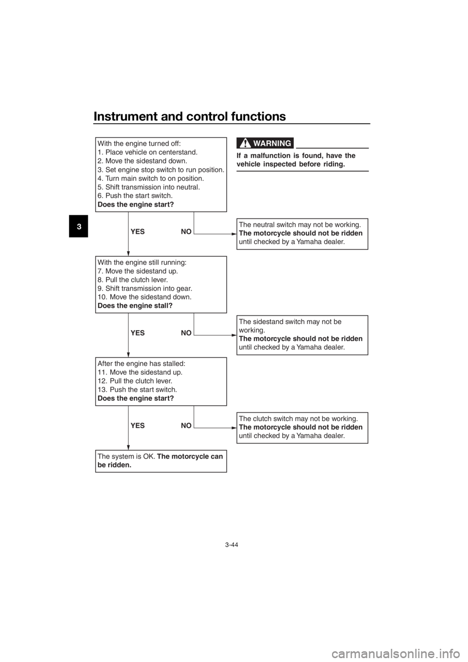
With the engine turned off:
1. Place vehicle on centerstand.
2. Move the sidestand down.
3. Set engine stop switch to run position.
4. Turn main switch to on position.
5. Shift transmission into neutral.
6. Push the start switch.
Does the engine start?
With the engine still running:
7. Move the sidestand up.
8. Pull the clutch lever.
9. Shift transmission into gear.
10. Move the sidestand down.
Does the engine stall?
After the engine has stalled:
11. Move the sidestand up.
12. Pull the clutch lever.
13. Push the start switch.
Does the engine start?
The system is OK. The motorcycle can
be ridden.
The neutral switch may not be working.
The motorcycle should not be ridden
until checked by a Yamaha dealer.
The sidestand switch may not be
working.
The motorcycle should not be ridden
until checked by a Yamaha dealer.
The clutch switch may not be working.
The motorcycle should not be ridden
until checked by a Yamaha dealer.
WARNING
If a malfunction is found, have the
vehicle inspected before riding.
YES NO
YESNO
YESNO
UB88E1E0.book Page 44 Monday, July 10, 2017 2:46 PM
Page 59 of 118
Instrument and control functions
3-45
3
EAU39657
Auxiliary DC jack
WARNING
EWA14361
To prevent electrical shock or short-
circuiting , make sure that the cap is
installe d when the auxiliary DC jack
is not bein g use d.
NOTICE
ECA15432
The accessory connecte d to the
auxiliary DC jack shoul d not b e used
with the en gine turne d off, an d the
loa d must never exceed 30 W (2.5 A),
otherwise the fuse may blow or the
b attery may d ischarge.
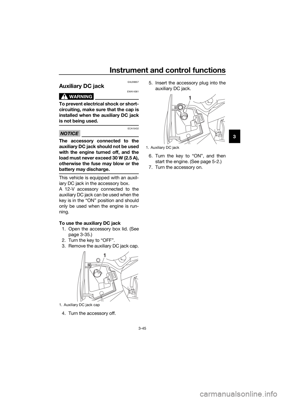
This vehicle is equipped with an auxil-
iary DC jack in the accessory box.
A 12-V accessory connected to the
auxiliary DC jack can be used when the
key is in the “ON” position and should
only be used when the engine is run-
ning.
To use the auxiliary DC jack
1. Open the accessory box lid. (See page 3-35.)
2. Turn the key to “OFF”.
3. Remove the auxiliary DC jack cap.
4. Turn the accessory off. 5. Insert the accessory plug into the
auxiliary DC jack.
6. Turn the key to “ON”, and then start the engine. (See page 5-2.)
7. Turn the accessory on.
1. Auxiliary DC jack cap
1
1. Auxiliary DC jack
1
UB88E1E0.book Page 45 Monday, July 10, 2017 2:46 PM
Page 60 of 118

For your safety – pre-operation checks
4-1
4
EAU63440
Inspect your vehicle each time you use it to make sure the vehicle is in safe oper-
ating condition. Always follow the inspection and maintenance procedures and
schedules described in the Owner’s Manual.
WARNING
EWA11152
Failure to inspect or maintain the vehicle properly increases the possibility
of an acci dent or equipment d amage. Do not operate the vehicle if you fin d
any pro blem. If a pro blem cannot be correcte d b y the proce dures provi ded
in this manual, have the vehicle inspecte d b y a Yamaha dealer.
Before using this vehicle, check the following points:
ITEM CHECKSPAGE
Fuel • Check fuel level in fuel tank.
• Refuel if necessary.
• Check fuel line for leakage.
• Check fuel tank overflow hose for obstructions, cracks
or damage, and check hose connection. 3-28,
3-30
En gine oil • Check oil level in engine.
• If necessary, add recommended oil to specified level.
• Check vehicle for oil leakage. 6-11
Final gear oil • Check vehicle for oil leakage. 6-14
Coolant • Check coolant level in reservoir.
• If necessary, add recommended coolant to specified
level.
• Check cooling system for leakage. 6-16
Front brake • Check operation.
• If soft or spongy, have Yamaha dealer bleed hydraulic
system.
• Check brake pads for wear.
• Replace if necessary.
• Check fluid level in reservoir.
• If necessary, add specified brake fluid to specified level.
• Check hydraulic system for leakage. 6-25,
6-26
Rear brake • Check operation.
• If soft or spongy, have Yamaha dealer bleed hydraulic
system.
• Check brake pads for wear.
• Replace if necessary.
• Check fluid level in reservoir.
• If necessary, add specified brake fluid to specified level.
• Check hydraulic system for leakage. 6-25,
6-26
UB88E1E0.book Page 1 Monday, July 10, 2017 2:46 PM
Page 62 of 118

Operation and important rid ing points
5-1
5
EAU15952
Read the Owner’s Manual carefully to
become familiar with all controls. If
there is a control or function you do not
understand, ask your Yamaha dealer.
WARNING
EWA10272
Failure to familiarize yourself with
the controls can lea d to loss of con-
trol, which coul d cause an acci dent
or injury.
EAU73451
TIP
This model is equipped with: a lean angle sensor to stop the en-
gine in case of turnover. Turn the
main switch off once before at-
tempting to restart the engine.
Failing to do so will prevent the en-
gine from starting, even though
the engine will crank when the
start switch is pushed.
an engine auto-stop system. The
engine stops automatically if left
idling for 20 minutes. In this case,
simply push the start switch to re-
start the engine.
UB88E1E0.book Page 1 Monday, July 10, 2017 2:46 PM
Page 63 of 118

Operation and important ri din g points
5-2
5
EAU54173
Startin g the eng ine
In order for the ignition circuit cut-off
system (page 3-43) to enable starting,
one of the following conditions must be
met:
the transmission is in neutral.
the clutch lever is pulled and the
sidestand up.
To start the engine
1. Turn the main switch to “ON” and set the engine stop switch to “ ”.
2. Confirm the following lights come on for a few seconds, and then go
off. Oil level warning light
Engine trouble warning light
TCS indicator light
Cruise control indicator lights
Immobilizer system indicator
light
ABS warning light*
Neutral indicator light*
TIP
The ABS warning light should go
off when the vehicle reaches a
traveling speed of 10 km/h (6
mi/h).
The neutral indicator light should
be on when the transmission is in
neutral.
NOTICE
ECA24110
If a warnin g or in dicator li ght does
not work as descri bed a bove, have a
Yamaha dealer check the vehicle.
3. Shift the transmission into neutral.
4. Push the start switch, and release
it when the engine starts. If the engine does not start within
5 seconds of pressing the start
switch, wait 10 seconds before
pressing the switch again to allow
the battery voltage to restore.
NOTICE
ECA11043
For maximum en
gine life, never ac-
celerate har d when the en gine is
col d!
UB88E1E0.book Page 2 Monday, July 10, 2017 2:46 PM
Page 66 of 118

Operation and important rid ing points
5-5
5
If any en gine trou ble shoul d oc-
cur during the en gine break-in
period , imme diately have a
Yamaha dealer check the vehi-
cle.
EAU17214
Parkin g
When parking, stop the engine, and
then remove the key from the main
switch.
WARNING
EWA10312
Since the en gine an d exhaust
system can become very hot,
park in a place where ped estri-
ans or chil dren are not likely to
touch them and b e burne d.
Do not park on a slope or on soft
groun d, otherwise the vehicle
may overturn, increasin g the
risk of a fuel leak an d fire.
Do not park near g rass or other
flammab le materials which
mi ght catch fire.
UB88E1E0.book Page 5 Monday, July 10, 2017 2:46 PM
Page 67 of 118
Periodic maintenance an d a djustment
6-1
6
EAU17246
Periodic inspection, adjustment, and
lubrication will keep your vehicle in the
safest and most efficient condition
possible. Safety is an obligation of the
vehicle owner/operator. The most im-
portant points of vehicle inspection,
adjustment, and lubrication are ex-
plained on the following pages.
The intervals given in the periodic
maintenance charts should be simply
considered as a general guide under
normal riding conditions. However, de-
pending on the weather, terrain, geo-
graphical location, and individual use,
the maintenance intervals may need to
be shortened.
WARNING
EWA10322
Failure to properly maintain the vehi-
cle or performin g maintenance ac-
tivities incorrectly may increase
your risk of injury or death during
service or while usin g the vehicle. If
you are not familiar with vehicle ser-
vice, have a Yamaha d ealer perform
service.
WARNING
EWA15123
Turn off the en gine when performin g
maintenance unless otherwise
specified .
A runnin g en gine has movin g
parts that can catch on body
parts or clothin g an d electrical
parts that can cause shocks or
fires.
Runnin g the en gine while ser-
vicin g can lead to eye injury,
b urns, fire, or car bon monoxi de
poisonin g – possi bly lea din g to d
eath. See pag e 1-3 for more in-
formation a bout car bon monox-
i d e.
WARNING
EWA15461
Brake discs, calipers, drums, an d
linin gs can b ecome very hot durin g
use. To avoi d possi ble burns, let
b rake components cool before
touching them.
UB88E1E0.book Page 1 Monday, July 10, 2017 2:46 PM
Page 80 of 118
Periodic maintenance an d a djustment
6-14
6 12. Start the engine, and then let it idle
for several minutes while checking
it for oil leakage. If oil is leaking,
immediately turn the engine off
and check for the cause.
TIP
After the engine is started, the engine
oil level warning light should go off if
the oil level is sufficient.
NOTICE
ECA10402
If the oil level warnin g li ght flickers
or remains on even if the oil level is
correct, immed iately turn the en gine
off an d have a Yamaha d ealer check
the vehicle.
13. Turn the engine off, and then check the oil level and correct it if
necessary.
EAU20017
Final gear oil
The final gear case must be checked
for oil leakage before each ride. If any
leakage is found, have a Yamaha deal-
er check and repair the vehicle. In ad-
dition, the final gear oil level must be
checked and the oil changed as fol-
lows at the intervals specified in the
periodic maintenance and lubrication
chart.
WARNING
EWA10371
Make sure that no forei gn mate-
rial enters the final gear case.
Make sure that no oil gets on
the tire or wheel.
To check the final gear oil level
1. Place the vehicle on the center- stand.
TIP
Make sure that the vehicle is posi-
tioned straight up when checking the
oil level. A slight tilt to the side can re-
sult in a false reading.
2. Remove the final gear oil filler boltand its gasket, and then check the
oil level in the final gear case.
TIP
The oil level should be at the brim of
the filler hole.
UB88E1E0.book Page 14 Monday, July 10, 2017 2:46 PM