clutch YAMAHA FJR1300AE 2014 Owners Manual
[x] Cancel search | Manufacturer: YAMAHA, Model Year: 2014, Model line: FJR1300AE, Model: YAMAHA FJR1300AE 2014Pages: 120, PDF Size: 3.33 MB
Page 6 of 120

TABLE OF CONTENTSSAFETY INFORMATION.................. 1-1
DESCRIPTION .................................. 2-1
Left view ......................................... 2-1
Right view ....................................... 2-2
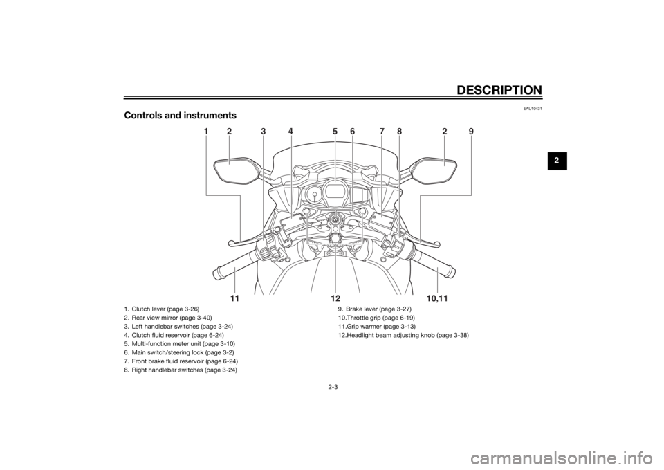
Controls and instruments ............... 2-3
INSTRUMENT AND CONTROL
FUNCTIONS ...................................... 3-1
Immobilizer system......................... 3-1
Main switch/steering lock............... 3-2
Indicator lights and warning lights............................................ 3-4
Cruise control system..................... 3-7
Multi-function meter unit .............. 3-10
D-mode (drive mode).................... 3-24
Handlebar switches ...................... 3-24
Clutch lever .................................. 3-26
Shift pedal .................................... 3-27
Brake lever.................................... 3-27
Brake pedal .................................. 3-27
ABS .............................................. 3-28
Traction control system ................ 3-29
Fuel tank cap ................................ 3-30
Fuel ............................................... 3-31
Fuel tank breather/
overflow hose ............................ 3-32
Catalytic converters...................... 3-32
Seats ............................................ 3-33
Adjusting the rider seat height...... 3-34
Storage compartments................. 3-36 Accessory box .............................. 3-37
Adjusting the headlight beams ..... 3-38
Handlebar position ........................ 3-38
Opening and closing the cowling
vents .......................................... 3-38
Rear view mirrors .......................... 3-40
Adjusting the front and rear suspension ................................ 3-40
Sidestand ...................................... 3-44
Ignition circuit cut-off system ....... 3-45
Auxiliary DC jack ........................... 3-47
FOR YOUR SAFETY –
PRE-OPERATION CHECKS ............. 4-1
OPERATION AND IMPORTANT
RIDING POINTS ................................ 5-1
Starting the engine .......................... 5-1
Shifting ............................................ 5-2
Tips for reducing fuel consumption ................................ 5-3
Engine break-in ............................... 5-3
Parking ............................................ 5-4
PERIODIC MAINTENANCE AND
ADJUSTMENT ................................... 6-1
Owner’s tool kit ............................... 6-2
Periodic maintenance chart for the emission control system .............. 6-3
General maintenance and lubrication chart ........................... 6-4 Removing and installing panels ...... 6-8
Checking the spark plugs ............. 6-11
Engine oil and oil filter cartridge ... 6-12
Final gear oil ................................. 6-14
Coolant ......................................... 6-16
Cleaning the air filter element ....... 6-17
Checking the engine idling
speed ........................................ 6-18
Checking the throttle grip free play ............................................ 6-19
Valve clearance............................. 6-19
Tires .............................................. 6-19
Cast wheels .................................. 6-22
Clutch lever................................... 6-22
Checking the brake lever free
play ............................................ 6-23
Brake light switches ..................... 6-23
Checking the front and rear brake
pads .......................................... 6-24
Checking the brake and clutch
fluid levels.................................. 6-24
Changing the brake and clutch fluids .......................................... 6-26
Checking and lubricating the cables ........................................ 6-26
Checking and lubricating the
throttle grip and cable ............... 6-26
Checking and lubricating the brake and shift pedals............... 6-27
Checking and lubricating the brake and clutch levers ............. 6-27U2PDE0E0.book Page 1 Monday, July 15, 2013 9:43 AM
Page 15 of 120
DESCRIPTION
2-3
2
EAU10431
Controls and instruments
12 3 4 56
78 2 9
10,11
12
11
1. Clutch lever (page 3-26)
2. Rear view mirror (page 3-40)
3. Left handlebar switches (page 3-24)
4. Clutch fluid reservoir (page 6-24)
5. Multi-function meter unit (page 3-10)
6. Main switch/steering lock (page 3-2)
7. Front brake fluid reservoir (page 6-24)
8. Right handlebar switches (page 3-24) 9. Brake lever (page 3-27)
10.Throttle grip (page 6-19)
11.Grip warmer (page 3-13)
12.Headlight beam adjusting knob (page 3-38)
U2PDE0E0.book Page 3 Monday, July 15, 2013 9:43 AM
Page 23 of 120
INSTRUMENT AND CONTROL FUNCTIONS
3-8
3
cruise control setting switch down will
increase or decrease the speed contin-
uously until the switch is released.
You can also manually increase your
traveling speed using the throttle. After
you have accelerated, you can set a
new cruising speed by pushing the
“SET–” side of the setting switch. If you
do not set a new cruising speed, when
you return the throttle grip, the vehicle
will decelerate to the previously set
cruising speed.
Deactivatin
g the cruise control sys-
tem
Perform one of the following opera-
tions to cancel the set cruising speed.
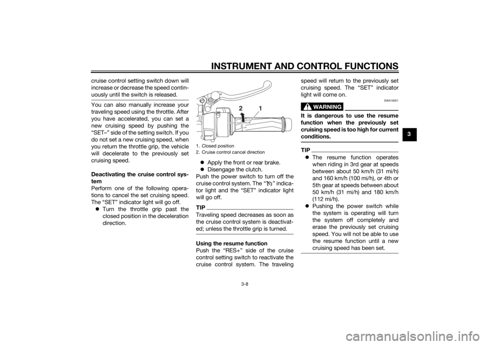
The “SET” indicator light will go off. Turn the throttle grip past the
closed position in the deceleration
direction.
Apply the front or rear brake.
Disengage the clutch.
Push the power switch to turn off the
cruise control system. The “ ” indica-
tor light and the “SET” indicator light
will go off.
TIPTraveling speed decreases as soon as
the cruise control system is deactivat-
ed; unless the throttle grip is turned.Usin g the resume function
Push the “RES+” side of the cruise
control setting switch to reactivate the
cruise control system. The traveling speed will return to the previously set
cruising speed. The “SET” indicator
light will come on.
WARNING
EWA16351
It is d
angerous to use the resume
function when the previously set
cruisin g speed is too hi gh for current
con ditions.TIP The resume function operates
when riding in 3rd gear at speeds
between about 50 km/h (31 mi/h)
and 160 km/h (100 mi/h), or 4th or
5th gear at speeds between about
50 km/h (31 mi/h) and 180 km/h
(112 mi/h).
Pushing the power switch while
the system is operating will turn
the system off completely and
erase the previously set cruising
speed. You will not be able to use
the resume function until a new
cruising speed has been set.
1. Closed position
2. Cruise control cancel direction
2
1
U2PDE0E0.book Page 8 Monday, July 15, 2013 9:43 AM
Page 41 of 120
INSTRUMENT AND CONTROL FUNCTIONS
3-26
3
EAU54221
Select switch “ / ”
This switch is used to perform selec-
tions in the function display and setting
mode display of the multi-function me-
ter unit.
See “Multi-function meter unit” on
page 3-10 for detailed information.
EAU54691
Drive mode switch “MODE”
WARNING
EWA15341
Do not chan ge the D-mod e while the
vehicle is movin g.Using this switch changes the drive
mode to touring mode “T” or sports
mode “S”.
The throttle grip must be completely
closed in order to change the drive
mode.
The selected mode is shown on the
drive mode display. (See page 3-12.)
The drive mode cannot be changed
while the cruise control system is oper-
ating.
EAU12831
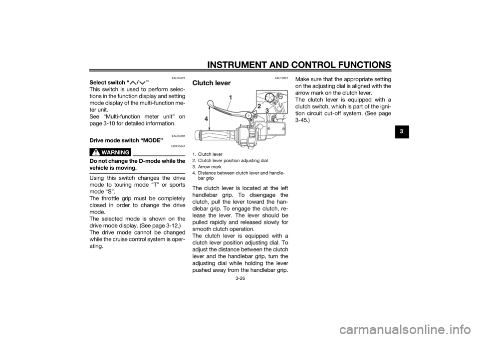
Clutch leverThe clutch lever is located at the left
handlebar grip. To disengage the
clutch, pull the lever toward the han-
dlebar grip. To engage the clutch, re-
lease the lever. The lever should be
pulled rapidly and released slowly for
smooth clutch operation.
The clutch lever is equipped with a
clutch lever position adjusting dial. To
adjust the distance between the clutch
lever and the handlebar grip, turn the
adjusting dial while holding the lever
pushed away from the handlebar grip. Make sure that the appropriate setting
on the adjusting dial is aligned with the
arrow mark on the clutch lever.
The clutch lever is equipped with a
clutch switch, which is part of the igni-
tion circuit cut-off system. (See page
3-45.)1. Clutch lever
2. Clutch lever position adjusting dial
3. Arrow mark
4. Distance between clutch lever and handle-
bar grip
15432
4 1
2
3
U2PDE0E0.book Page 26 Monday, July 15, 2013 9:43 AM
Page 42 of 120
INSTRUMENT AND CONTROL FUNCTIONS
3-27
3
EAU12872
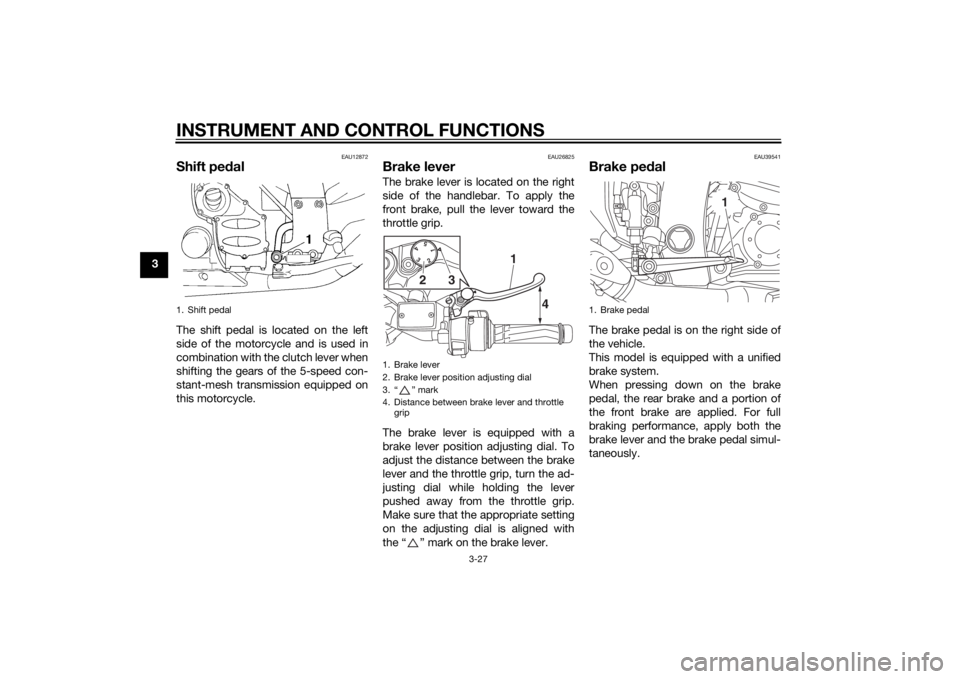
Shift pedalThe shift pedal is located on the left
side of the motorcycle and is used in
combination with the clutch lever when
shifting the gears of the 5-speed con-
stant-mesh transmission equipped on
this motorcycle.
EAU26825
Brake leverThe brake lever is located on the right
side of the handlebar. To apply the
front brake, pull the lever toward the
throttle grip.
The brake lever is equipped with a
brake lever position adjusting dial. To
adjust the distance between the brake
lever and the throttle grip, turn the ad-
justing dial while holding the lever
pushed away from the throttle grip.
Make sure that the appropriate setting
on the adjusting dial is aligned with
the “ ” mark on the brake lever.
EAU39541
Brake ped alThe brake pedal is on the right side of
the vehicle.
This model is equipped with a unified
brake system.
When pressing down on the brake
pedal, the rear brake and a portion of
the front brake are applied. For full
braking performance, apply both the
brake lever and the brake pedal simul-
taneously.
1. Shift pedal
1. Brake lever
2. Brake lever position adjusting dial
3. “ ” mark
4. Distance between brake lever and throttle
grip
15
43
2
4
1
3
2
1. Brake pedal
1
U2PDE0E0.book Page 27 Monday, July 15, 2013 9:43 AM
Page 60 of 120

INSTRUMENT AND CONTROL FUNCTIONS
3-45
3this system reg
ularly and have a
Yamaha dealer repair it if it does not
function properly.
EAU54491
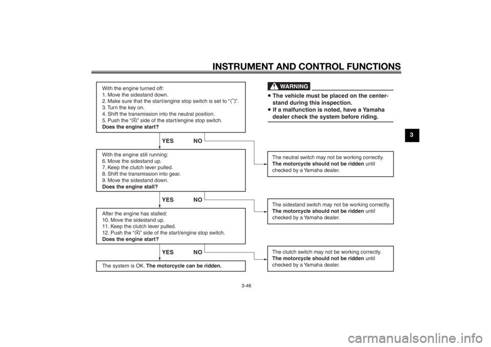
I g nition circuit cut-off systemThe ignition circuit cut-off system
(comprising the sidestand switch,
clutch switch and neutral switch) has
the following functions.
It prevents starting when the
transmission is in gear and the
sidestand is up, but the clutch le-
ver is not pulled.
It prevents starting when the
transmission is in gear and the
clutch lever is pulled, but the side-
stand is still down.
It cuts the running engine when
the transmission is in gear and the
sidestand is moved down.
Periodically check the operation of the
ignition circuit cut-off system accord-
ing to the following procedure.
U2PDE0E0.book Page 45 Monday, July 15, 2013 9:43 AM
Page 61 of 120
INSTRUMENT AND CONTROL FUNCTIONS
3-46
3
With the engine turned off:
1. Move the sidestand down.
2. Make sure that the start/engine stop switch is set to “ ”.
3. Turn the key on.
4. Shift the transmission into the neutral position.
5. Push the “ ” side of the start/engine stop switch.
Does the engine start?
With the engine still running:
6. Move the sidestand up.
7. Keep the clutch lever pulled.
8. Shift the transmission into gear.
9. Move the sidestand down.
Does the engine stall?
After the engine has stalled:
10. Move the sidestand up.
11. Keep the clutch lever pulled.
12. Push the “ ” side of the start/engine stop switch.
Does the engine start?
The system is OK. The motorcycle can be ridden.
YES NO YES NO YES NO
The neutral switch may not be working correctly.
The motorcycle should not be ridden until
checked by a Yamaha dealer.
The clutch switch may not be working correctly.
The motorcycle should not be ridden until
checked by a Yamaha dealer.The sidestand switch may not be working correctly.
The motorcycle should not be ridden until
checked by a Yamaha dealer.• The vehicle must be placed on the center-
stand during this inspection.• If a malfunction is noted, have a Yamaha
dealer check the system before riding.
WA R N I N G
U2PDE0E0.book Page 46 Monday, July 15, 2013 9:43 AM
Page 64 of 120

FOR YOUR SAFETY – PRE-OPERATION CHECKS
4-2
4
Rear brake • Check operation.
• If soft or spongy, have Yamaha dealer bleed hydraulic system.
• Check brake pads for wear.
• Replace if necessary.
• Check fluid level in reservoir.
• If necessary, add specified brake fluid to specified level.
• Check hydraulic system for leakage. 6-24, 6-24
Clutch • Check operation.
• If soft or spongy, have Yamaha dealer bleed hydraulic system.
• Check fluid level in reservoir.
• If necessary, add specified brake fluid to specified level.
• Check hydraulic system for leakage. 6-22, 6-24
Throttle g rip • Make sure that operation is smooth.
• Check throttle grip free play.
• If necessary, have Yamaha dealer adjust throttle grip free play and lubricate ca-
ble and grip housing. 6-19, 6-26
Control ca bles • Make sure that operation is smooth.
• Lubricate if necessary. 6-26
Wheels an d tires •Check for damage.
• Check tire condition and tread depth.
• Check air pressure.
• Correct if necessary.
6-19, 6-22
Brake an d shift pe dals • Make sure that operation is smooth.
• Lubricate pedal pivoting points if necessary.
6-27
Brake an d clutch levers • Make sure that operation is smooth.
• Lubricate lever pivoting points if necessary. 6-27
Centerstan d, si destan d • Make sure that operation is smooth.
• Lubricate pivots if necessary.
6-28
Chassis fasteners • Make sure that all nuts, bolts and screws are properly tightened.
• Tighten if necessary.
—
ITEM
CHECKS PAGE
U2PDE0E0.book Page 2 Monday, July 15, 2013 9:43 AM
Page 66 of 120
OPERATION AND IMPORTANT RIDING POINTS
5-1
5
EAU15952
Read the Owner’s Manual carefully to
become familiar with all controls. If
there is a control or function you do not
understand, ask your Yamaha dealer.
WARNING
EWA10272
Failure to familiarize yourself with
the controls can lead to loss of con-
trol, which coul d cause an acci dent
or injury.
EAU47151
TIPThis model is equipped with: a lean angle sensor to stop the en-
gine in case of a turnover. In this
case, the multi-function meter unit
indicates error code 30, but this is
not a malfunction. Turn the key to
“OFF” and then to “ON” to clear
the error code. Failing to do so will
prevent the engine from starting
even though the engine will crank
when pushing the start switch.
an engine auto-stop system. The
engine stops automatically if left
idling for 20 minutes. In this case,
the multi-function meter unit indi-
cates error code 70, but this is not
a malfunction. Push the start
switch to clear the error code and
to restart the engine.
EAU58240
Startin g the en gineIn order for the ignition circuit cut-off
system to enable starting, one of the
following conditions must be met:
The transmission is in the neutral
position.
The transmission is in gear with
the clutch lever pulled and the
sidestand up.
See page 3-45 for more informa-
tion.
1. Turn the key to “ON” and make sure that the start/engine stop
switch is set to “ ”.
The following warning lights and
indicator lights should come on for
a few seconds, then go off. Oil level warning light
Engine trouble warning light
Traction control system indi-
cator/warning light
Cruise control indicator lights
Electronically adjustable sus-
pension system warning light
Immobilizer system indicator
light
U2PDE0E0.book Page 1 Monday, July 15, 2013 9:43 AM
Page 68 of 120

OPERATION AND IMPORTANT RIDING POINTS
5-3
5
NOTICE
ECA10261
Even with the transmission in
the neutral position, do not
coast for lon g period s of time
with the en gine off, an d d o not
tow the motorcycle for lon g d is-
tances. The transmission is
properly lu bricated only when
the en gine is runnin g. Ina de-
quate lu brication may damag e
the transmission.
Always use the clutch while
chan gin g g ears to avoi d d am-
a g in g the en gine, transmission,
an d d rive train, which are not
d esi gne d to withstan d the
shock of force d shifting .
EAU16811
Tips for re ducin g fuel con-
sumptionFuel consumption depends largely on
your riding style. Consider the follow-
ing tips to reduce fuel consumption:
Shift up swiftly, and avoid high en-
gine speeds during acceleration.
Do not rev the engine while shift-
ing down, and avoid high engine
speeds with no load on the en-
gine.
Turn the engine off instead of let-
ting it idle for an extended length
of time (e.g., in traffic jams, at traf-
fic lights or at railroad crossings).
EAU16842
Engine break-inThere is never a more important period
in the life of your engine than the period
between 0 and 1600 km (1000 mi). For
this reason, you should read the fol-
lowing material carefully.
Since the engine is brand new, do not
put an excessive load on it for the first
1600 km (1000 mi). The various parts in
the engine wear and polish themselves
to the correct operating clearances.
During this period, prolonged full-throt-
tle operation or any condition that
might result in engine overheating
must be avoided.
EAU17124
0–1000 km (0–600 mi)
Avoid prolonged operation above 4500
r/min. NOTICE: After 1000 km (600
mi) of operation, the en gine oil an d
final gear oil must be chan ged , an d
the oil filter cartri dge or element re-
placed .
[ECA10333]
U2PDE0E0.book Page 3 Monday, July 15, 2013 9:43 AM