maintenance YAMAHA FJR1300AE 2016 Owners Manual
[x] Cancel search | Manufacturer: YAMAHA, Model Year: 2016, Model line: FJR1300AE, Model: YAMAHA FJR1300AE 2016Pages: 122, PDF Size: 3.4 MB
Page 5 of 122

Table of contents
Safety information ............................1-1
Description ........................................2-1
Left view ..........................................2-1
Right view........................................2-2
Controls and instruments ................2-3
Instrument an d control functions ....3-1
Immobilizer system .........................3-1
Main switch/steering lock ...............3-2
Indicator lights and warning lights ............................................3-4
Cruise control system .....................3-7
Multi-function meter unit ...............3-10
D-mode (drive mode) ....................3-22
Handlebar switches.......................3-23
Clutch lever ...................................3-24
Shift pedal .....................................3-25
Brake lever ....................................3-25
Brake pedal ...................................3-26
ABS ...............................................3-26
Traction control system.................3-27
Fuel tank cap.................................3-29
Fuel................................................3-29
Fuel tank overflow hose ................3-31
Catalytic converters .....................3-31
Seats .............................................3-32
Adjusting the rider seat height ......3-33
Storage compartments .................3-35
Accessory box...............................3-36
Adjusting the headlight beams......3-37
Handlebar position ........................3-38
Opening and closing the cowling vents ..........................................3-38
Rear view mirrors ..........................3-40
Adjusting the front and rear
suspension.................................3-40
Sidestand ......................................3-45
Ignition circuit cut-off system........3-45
Auxiliary DC jack ...........................3-47
Cornering lights .............................3-48 For your safety – pre-operation
checks
............................................... 4-1
Operation an d important ri din g
points ................................................. 5-1
Starting the engine.......................... 5-2
Shifting ............................................ 5-3
Tips for reducing fuel consumption................................ 5-4
Engine break-in ............................... 5-5
Parking ............................................ 5-6
Perio dic maintenance an d
a d justment ........................................ 6-1
Owner’s tool kit ............................... 6-2
Periodic maintenance chart for the emission control system.............. 6-3
General maintenance and lubrication chart........................... 6-4
Removing and installing panels ...... 6-7
Checking the spark plugs ............. 6-10
Canister......................................... 6-11
Engine oil and oil filter cartridge ... 6-11
Final gear oil.................................. 6-14
Coolant ......................................... 6-15
Cleaning the air filter element ....... 6-17
Checking the engine idling
speed......................................... 6-18
Checking the throttle grip free
play ............................................ 6-19
Valve clearance ............................. 6-19
Tires .............................................. 6-20
Cast wheels .................................. 6-22
Clutch lever ................................... 6-23
Checking the brake lever free play ............................................ 6-23
Brake light switches ...................... 6-24
Checking the front and rear brake pads................................. 6-24
Checking the brake and clutch fluid levels .................................. 6-25
Changing the brake and clutch fluids .......................................... 6-27
Checking and lubricating the cables ........................................ 6-27
UB96E0E0.book Page 1 Wednesday, November 4, 2015 5:01 PM
Page 7 of 122

1-1
1
Safety information
EAU1028B
Be a Responsible Owner
As the vehicle’s owner, you are re-
sponsible for the safe and proper oper-
ation of your motorcycle.
Motorcycles are single-track vehicles.
Their safe use and operation are de-
pendent upon the use of proper riding
techniques as well as the expertise of
the operator. Every operator should
know the following requirements be-
fore riding this motorcycle.
He or she should: Obtain thorough instructions from
a competent source on all aspects
of motorcycle operation.
Observe the warnings and mainte-
nance requirements in this Own-
er’s Manual.
Obtain qualified training in safe
and proper riding techniques.
Obtain professional technical ser-
vice as indicated in this Owner’s
Manual and/or when made neces-
sary by mechanical conditions.
Never operate a motorcycle with-
out proper training or instruction.
Take a training course. Beginners
should receive training from a cer-
tified instructor. Contact an autho-
rized motorcycle dealer to find out
about the training courses nearest
you.
Safe Ri din g
Perform the pre-operation checks
each time you use the vehicle to make
sure it is in safe operating condition.
Failure to inspect or maintain the vehi-
cle properly increases the possibility of an accident or equipment damage.
See page 4-1 for a list of pre-operation
checks.
This motorcycle is designed to
carry the operator and a passen-
ger.
The failure of motorists to detect
and recognize motorcycles in traf-
fic is the predominating cause of
automobile/motorcycle accidents.
Many accidents have been
caused by an automobile driver
who did not see the motorcycle.
Making yourself conspicuous ap-
pears to be very effective in reduc-
ing the chance of this type of
accident.
Therefore:
• Wear a brightly colored jacket.
• Use extra caution when you are approaching and passing
through intersections, since in-
tersections are the most likely
places for motorcycle accidents
to occur.
• Ride where other motorists can see you. Avoid riding in another
motorist’s blind spot.
• Never maintain a motorcycle without proper knowledge.
Contact an authorized motorcy-
cle dealer to inform you on ba-
sic motorcycle maintenance.
Certain maintenance can only
be carried out by certified staff.
UB96E0E0.book Page 1 Wednesday, November 4, 2015 5:01 PM
Page 30 of 122
Instrument and control functions
3-16
3 To reset the average fuel consumption
display, use the select switch to select
the information display that contains
the average fuel consumption display.
Push the “RESET” button briefly so
that the average fuel consumption dis-
play flashes, and then push the “RE-
SET” button again for 2 seconds while
the display is flashing.TIP
After resetting the average fuel con-
sumption display, “_ _._” will be shown
for that display until the vehicle has
traveled 1 km (0.6 mi).
NOTICE
ECA15474
If there is a malfunction, “– –.–” will
b
e continuously displaye d. Have a
Yamaha dealer check the vehicle.
Instantaneous fuel consumption dis-
play:
The instantaneous fuel consumption
display modes “km/L”, “L/100km” or
“MPG” show the fuel consumption un-
der the current riding conditions.
The “km/L” display shows the dis-
tance that can be traveled on 1.0 L
of fuel.
The “L/100km” display shows the
amount of fuel necessary to travel
100 km.
The “MPG” display shows the dis-
tance that can be traveled on
1.0 Imp.gal of fuel.
TIP
If traveling at speeds under 10 km/h (6
mi/h), “_ _._” will be displayed.
NOTICE
ECA15474
If there is a malfunction, “– –.–” will
be continuously displaye d. Have a
Yamaha dealer check the vehicle.
A djustin g the wind shield position
To move the windshield up, push
the “ ” side of the select switch. To
move the windshield down, push
the “ ” side of the select switch.
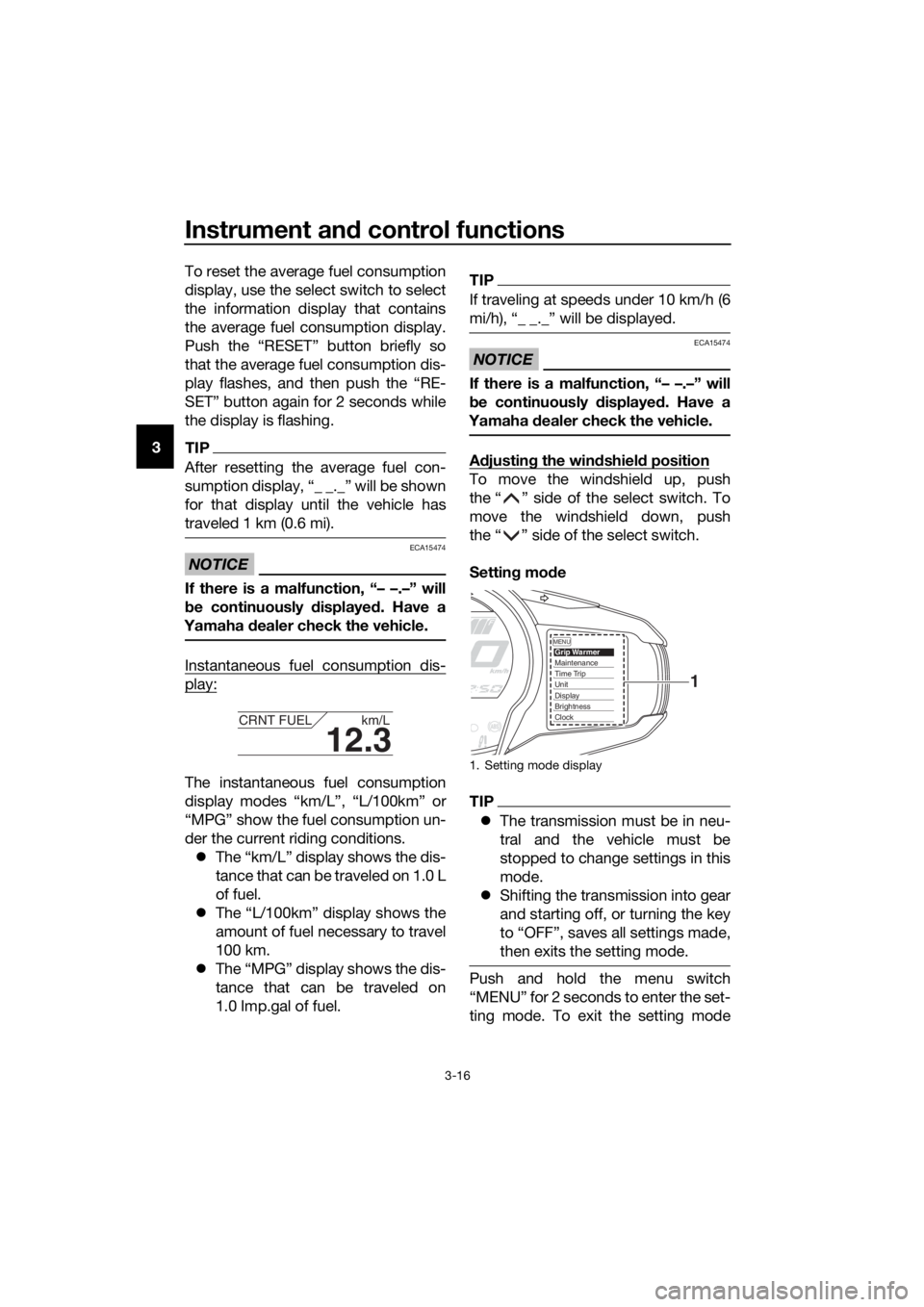
Settin g mo de
TIP
The transmission must be in neu-
tral and the vehicle must be
stopped to change settings in this
mode.
Shifting the transmission into gear
and starting off, or turning the key
to “OFF”, saves all settings made,
then exits the setting mode.
Push and hold the menu switch
“MENU” for 2 seconds to enter the set-
ting mode. To exit the setting mode
12.3
CRNT FUEL km/L
1. Setting mode display
MENUGrip WarmerMaintenanceTime TripUnitDisplayBrightnessClock
1
UB96E0E0.book Page 16 Wednesday, November 4, 2015 5:01 PM
Page 31 of 122
Instrument and control functions
3-17
3
and return to the normal display, push
and hold the menu switch “MENU”
again for at least 2 seconds.
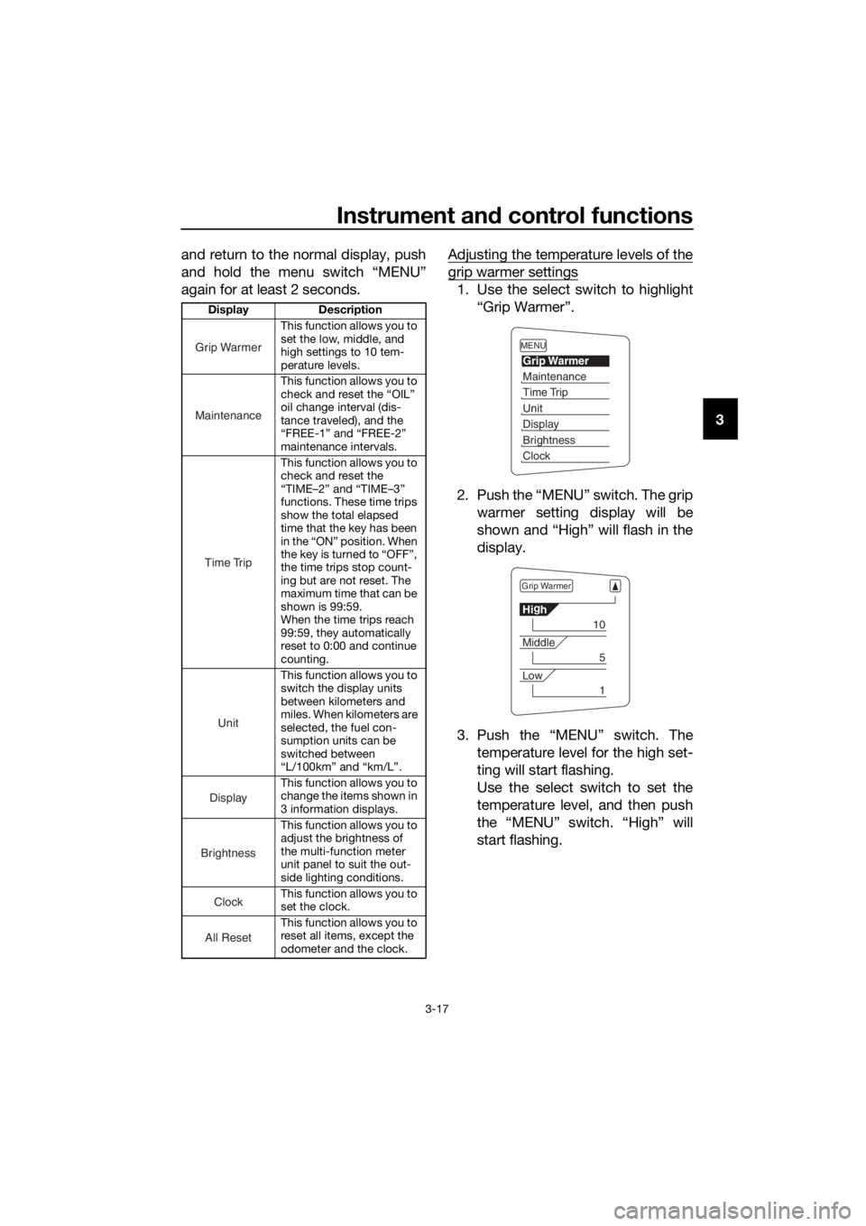
Adjusting the temperature levels of the
grip warmer settings
1. Use the select switch to highlight
“Grip Warmer”.
2. Push the “MENU” switch. The grip warmer setting display will be
shown and “High” will flash in the
display.
3. Push the “MENU” switch. The temperature level for the high set-
ting will start flashing.
Use the select switch to set the
temperature level, and then push
the “MENU” switch. “High” will
start flashing.
Display Description
This function allows you to
set the low, middle, and
high settings to 10 tem-
perature levels.
This function allows you to
check and reset the “OIL”
oil change interval (dis-
tance traveled), and the
“FREE-1” and “FREE-2”
maintenance intervals.
This function allows you to
check and reset the
“TIME–2” and “TIME–3”
functions. These time trips
show the total elapsed
time that the key has been
in the “ON” position. When
the key is turned to “OFF”,
the time trips stop count-
ing but are not reset. The
maximum time that can be
shown is 99:59.
When the time trips reach
99:59, they automatically
reset to 0:00 and continue
counting.
This function allows you to
switch the display units
between kilometers and
miles. When kilometers are
selected, the fuel con-
sumption units can be
switched between
“L/100km” and “km/L”.
This function allows you to
change the items shown in
3 information displays.
This function allows you to
adjust the brightness of
the multi-function meter
unit panel to suit the out-
side lighting conditions.
This function allows you to
set the clock.
This function allows you to
reset all items, except the
odometer and the clock.
Grip Warmer
Maintenance
Time Trip
Unit
Display
Brightness
Clock
All Reset
MENU
Grip Warmer
Maintenance
Time Trip
Unit
Display
Brightness
Clock
Grip Warmer
Hi g
h
10
Middle
5
Low
1
UB96E0E0.book Page 17 Wednesday, November 4, 2015 5:01 PM
Page 32 of 122
Instrument and control functions
3-18
3
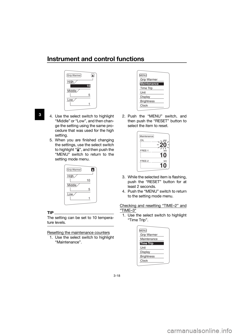
4. Use the select switch to highlight
“Middle” or “Low”, and then chan-
ge the setting using the same pro-
cedure that was used for the high
setting.
5. When you are finished changing the settings, use the select switch
to highlight “ ”, and then push the
“MENU” switch to return to the
setting mode menu.
TIP
The setting can be set to 10 tempera-
ture levels.
Resetting the maintenance counters
1. Use the select switch to highlight“Maintenance”. 2. Push the “MENU” switch, and
then push the “RESET” button to
select the item to reset.
3. While the selected item is flashing, push the “RESET” button for at
least 2 seconds.
4. Push the “MENU” switch to return to the setting mode menu.
Checking and resetting “TIME–2” and
“TIME–3”
1. Use the select switch to highlight “Time Trip”.
Grip Warmer
Hig
h
10
Middle
5
Low
1
Grip Warmer
Hi g
h
10
Middle
5
Low
1
MENU
Grip Warmer
Maintenance
Time Trip
Unit
Display
Brightness
Clock
20
OIL km
10
FREE-1km
10
FREE-2km
Maintenance
MENU
Grip Warmer
Maintenance
Time Trip
Unit
Display
Brightness
Clock
UB96E0E0.book Page 18 Wednesday, November 4, 2015 5:01 PM
Page 33 of 122
Instrument and control functions
3-19
3
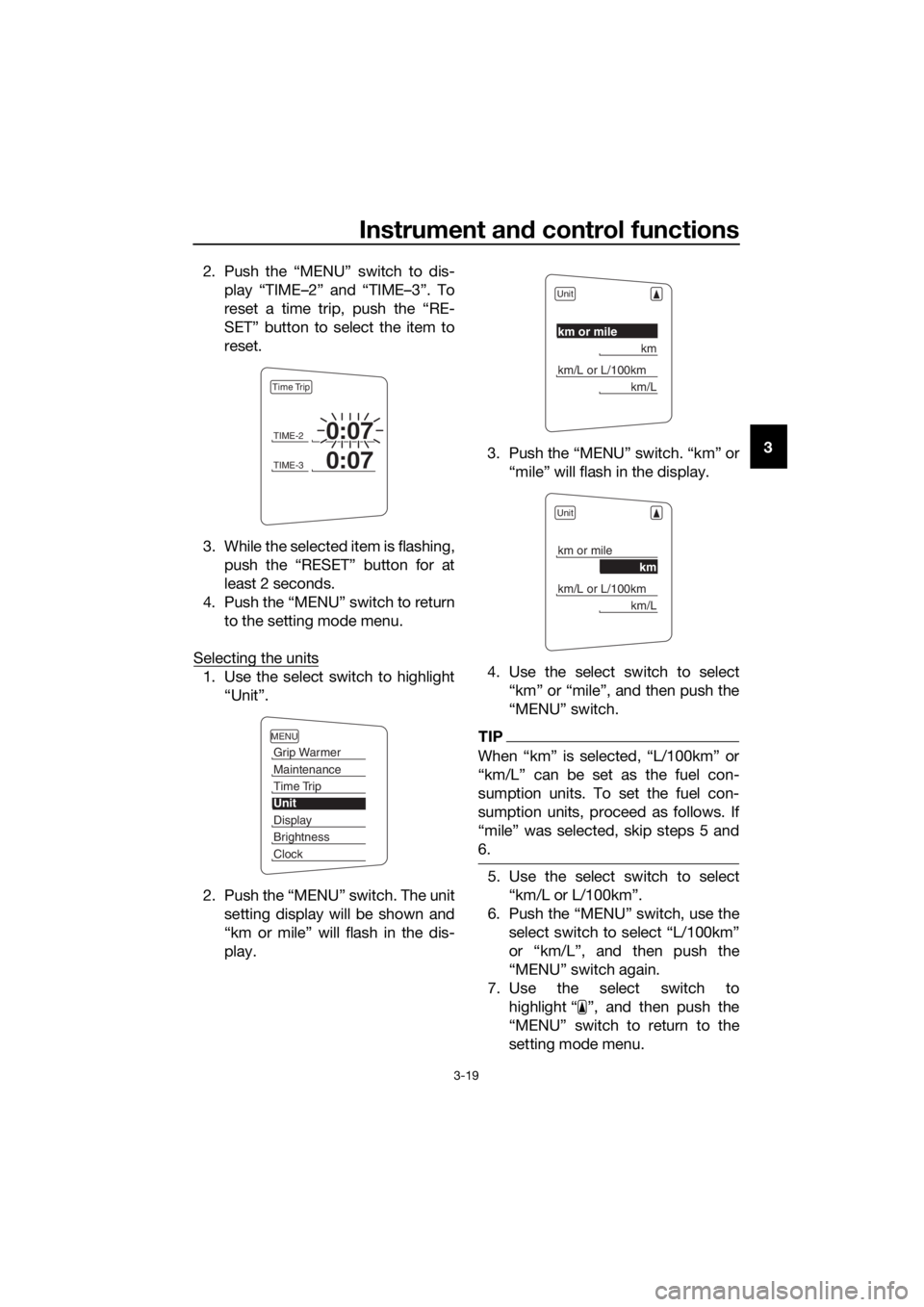
2. Push the “MENU” switch to dis-
play “TIME–2” and “TIME–3”. To
reset a time trip, push the “RE-
SET” button to select the item to
reset.
3. While the selected item is flashing, push the “RESET” button for at
least 2 seconds.
4. Push the “MENU” switch to return to the setting mode menu.
Selecting the units
1. Use the select switch to highlight “Unit”.
2. Push the “MENU” switch. The unit setting display will be shown and
“km or mile” will flash in the dis-
play. 3. Push the “MENU” switch. “km” or
“mile” will flash in the display.
4. Use the select switch to select “km” or “mile”, and then push the
“MENU” switch.
TIP
When “km” is selected, “L/100km” or
“km/L” can be set as the fuel con-
sumption units. To set the fuel con-
sumption units, proceed as follows. If
“mile” was selected, skip steps 5 and
6.
5. Use the select switch to select“km/L or L/100km”.
6. Push the “MENU” switch, use the select switch to select “L/100km”
or “km/L”, and then push the
“MENU” switch again.
7. Use the select switch to highlight “ ”, and then push the
“MENU” switch to return to the
setting mode menu.
TIME-20:07
TIME-30:07
Time Trip
MENU
Grip Warmer
Maintenance
Time Trip
Unit
Display
Brightness
Clock
Unit
km or mile
km
km/L or L/100km
km/L
Unit
km or mile
km
km/L or L/100km
km/L
UB96E0E0.book Page 19 Wednesday, November 4, 2015 5:01 PM
Page 34 of 122
Instrument and control functions
3-20
3
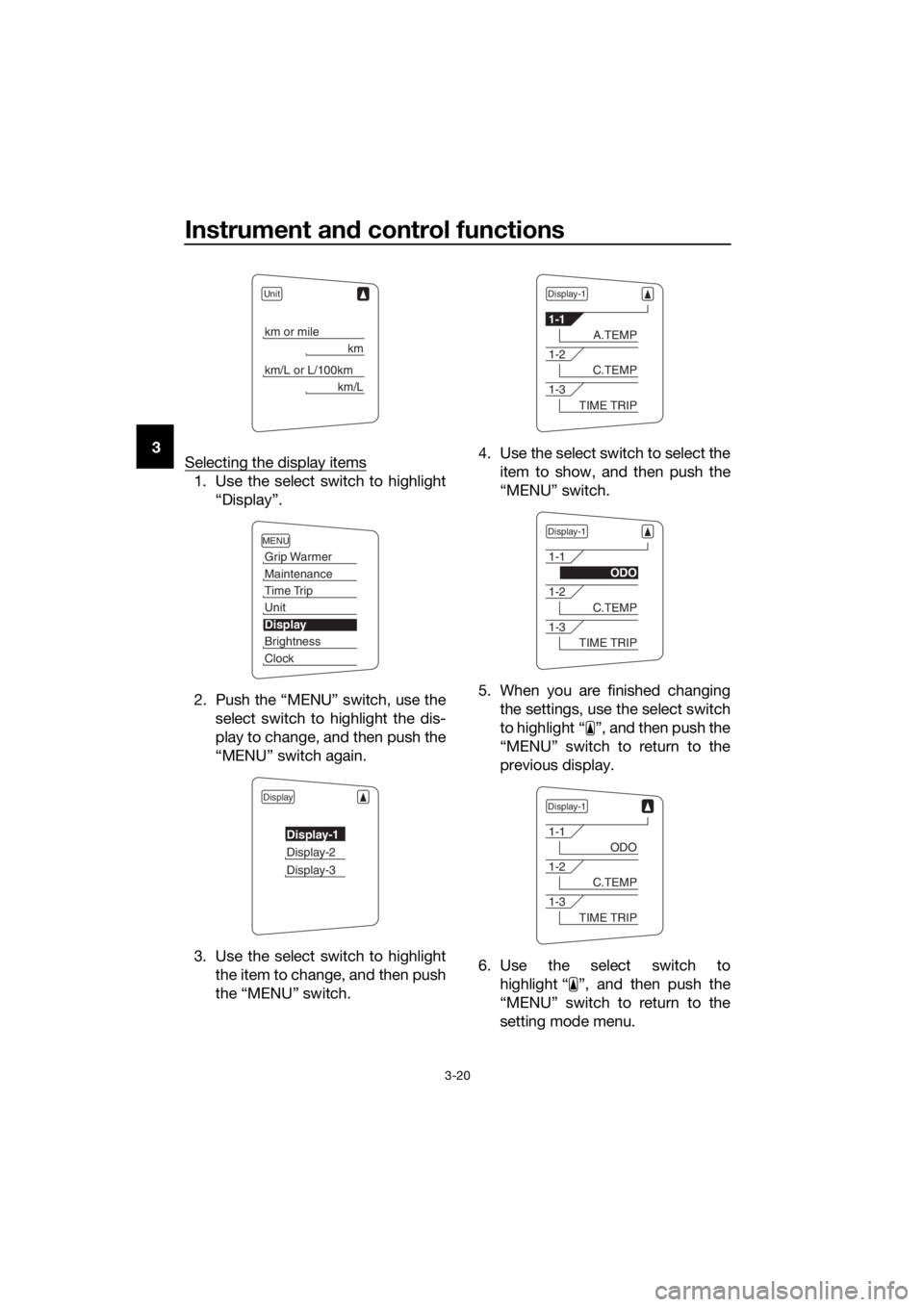
Selecting the display items
1. Use the select switch to highlight
“Display”.
2. Push the “MENU” switch, use the select switch to highlight the dis-
play to change, and then push the
“MENU” switch again.
3. Use the select switch to highlight the item to change, and then push
the “MENU” switch. 4. Use the select switch to select the
item to show, and then push the
“MENU” switch.
5. When you are finished changing the settings, use the select switch
to highlight “ ”, and then push the
“MENU” switch to return to the
previous display.
6. Use the select switch to highlight “ ”, and then push the
“MENU” switch to return to the
setting mode menu.
Unit
km or mile
km
km/L or L/100km
km/L
MENU
Grip Warmer
Maintenance
Time Trip
Unit
Display
Brightness
Clock
Display
Display-1
Display-2
Display-3
Display-1
1-1
A.TEMP
1-2
C.TEMP
1-3
TIME TRIP
Display-1
1-1
ODO
1-2
C.TEMP
1-3
TIME TRIP
Display-1
1-1
ODO
1-2
C.TEMP
1-3
TIME TRIP
UB96E0E0.book Page 20 Wednesday, November 4, 2015 5:01 PM
Page 35 of 122
Instrument and control functions
3-21
3
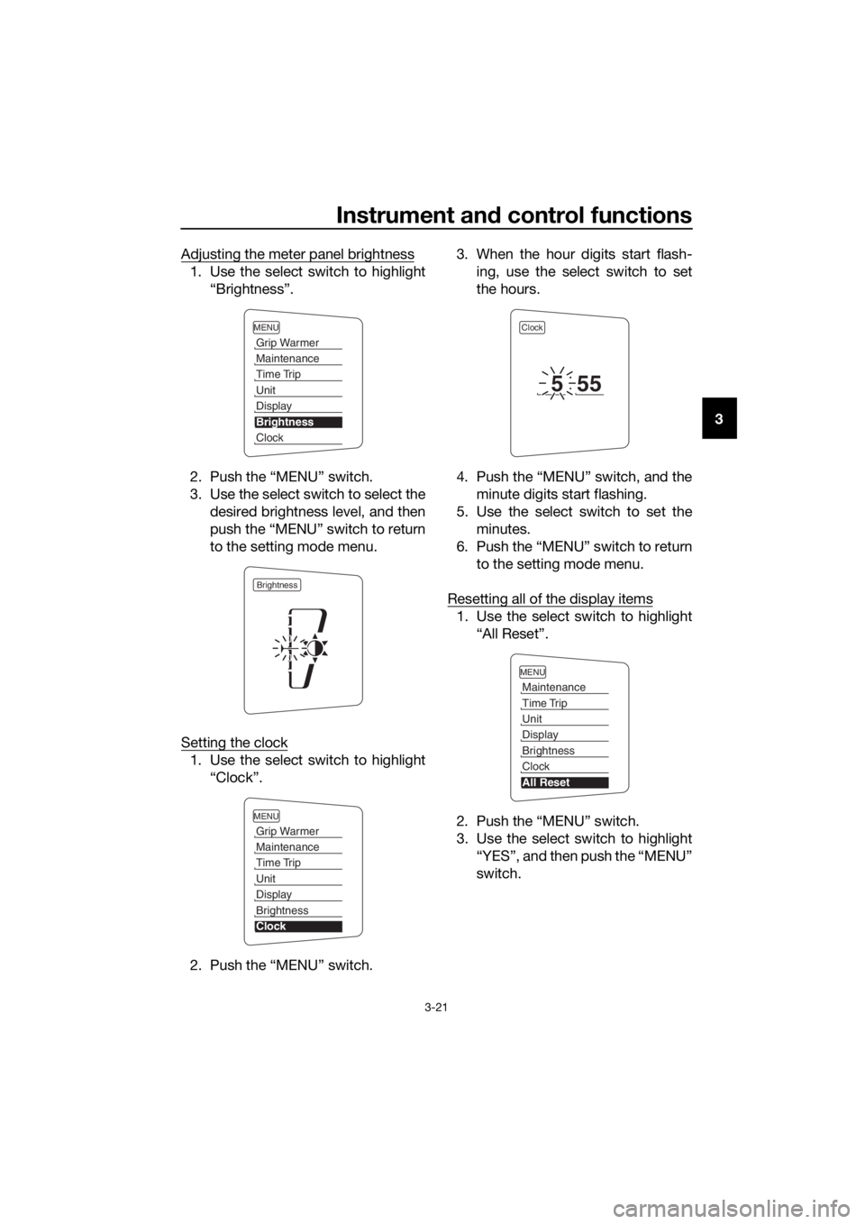
Adjusting the meter panel brightness
1. Use the select switch to highlight
“Brightness”.
2. Push the “MENU” switch.
3. Use the select switch to select the desired brightness level, and then
push the “MENU” switch to return
to the setting mode menu.
Setting the clock
1. Use the select switch to highlight “Clock”.
2. Push the “MENU” switch. 3. When the hour digits start flash-
ing, use the select switch to set
the hours.
4. Push the “MENU” switch, and the minute digits start flashing.
5. Use the select switch to set the minutes.
6. Push the “MENU” switch to return to the setting mode menu.
Resetting all of the display items
1. Use the select switch to highlight “All Reset”.
2. Push the “MENU” switch.
3. Use the select switch to highlight “YES”, and then push the “MENU”
switch.
MENU
Grip Warmer
Maintenance
Time Trip
Unit
Display
Brightness
Clock
Brightness
MENU
Grip Warmer
Maintenance
Time Trip
Unit
Display
Brightness
Clock
Clock
555
MENU
Maintenance
Time Trip
Unit
Display
Brightness
Clock
All Reset
UB96E0E0.book Page 21 Wednesday, November 4, 2015 5:01 PM
Page 44 of 122
Instrument and control functions
3-30
3 3. Wipe up any spilled fuel immedi-
ately. NOTICE: Immediately
wipe off spille d fuel with a clean,
d ry, soft cloth, since fuel may
d eteriorate painted surfaces or
plastic parts.
[ECA10072]
4. Be sure to securely close the fuel tank cap.
WARNING
EWA15152
Gasoline is poisonous an d can cau-
se injury or death. Han dle gasoline
with care. Never siphon gasoline by
mouth. If you shoul d swallow some
g asoline or inhale a lot of gasoline
vapor, or g et some gasoline in your
eyes, see your d octor immediately. If
g asoline spills on your skin, wash
with soap an d water. If g asoline
spills on your clothin g, chan ge your
clothes.
EAU49743
NOTICE
ECA11401
Use only unlea ded g asoline. The use
of lea ded g asoline will cause severe
d amag e to internal en gine parts,
such as the valves an d piston rin gs,
as well as to the exhaust system.
Your Yamaha engine has been de-
signed to use regular unleaded gaso-
line with a research octane number of 95 or higher. If knocking (or pinging)
occurs, use a gasoline of a different
brand or premium unleaded fuel. Use
of unleaded fuel will extend spark plug
life and reduce maintenance costs.
Gasohol
There are two types of gasohol: gaso-
hol containing ethanol and that con-
taining methanol. Gasohol containing
ethanol can be used if the ethanol con-
tent does not exceed 10% (E10). Gas-
ohol containing methanol is not
recommended by Yamaha because it
can cause damage to the fuel system
or vehicle performance problems.
Recommen
ded fuel:
Regular unleaded gasoline (Gasohol
[E10] acceptable)
Fuel tank capacity: 25 L (6.6 US gal, 5.5 Imp.gal)
Fuel reserve amount:
5.5 L (1.45 US gal, 1.21 Imp.gal)
UB96E0E0.book Page 30 Wednesday, November 4, 2015 5:01 PM
Page 45 of 122
Instrument and control functions
3-31
3
EAU72970
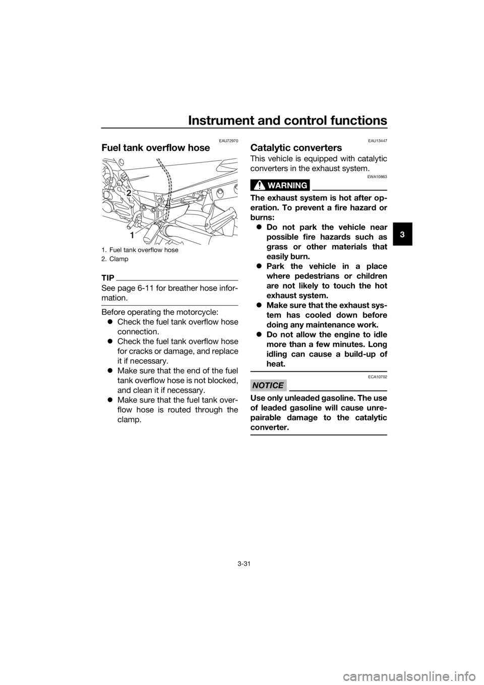
Fuel tank overflow hose
TIP
See page 6-11 for breather hose infor-
mation.
Before operating the motorcycle:
Check the fuel tank overflow hose
connection.
Check the fuel tank overflow hose
for cracks or damage, and replace
it if necessary.
Make sure that the end of the fuel
tank overflow hose is not blocked,
and clean it if necessary.
Make sure that the fuel tank over-
flow hose is routed through the
clamp.
EAU13447
Catalytic converters
This vehicle is equipped with catalytic
converters in the exhaust system.
WARNING
EWA10863
The exhaust system is hot after op-
eration. To prevent a fire hazar d or
b urns:
Do not park the vehicle near
possi ble fire hazar ds such as
g rass or other materials that
easily burn.
Park the vehicle in a place
where pe destrians or chil dren
are not likely to touch the hot
exhaust system.
Make sure that the exhaust sys-
tem has coole d down before
d oin g any maintenance work.
Do not allow the en gine to i dle
more than a few minutes. Lon g
i d lin g can cause a b uild-up of
heat.
NOTICE
ECA10702
Use only unlea ded g asoline. The use
of lead ed g asoline will cause unre-
paira ble damag e to the catalytic
converter.
1. Fuel tank overflow hose
2. Clamp
2
1
UB96E0E0.book Page 31 Wednesday, November 4, 2015 5:01 PM