display YAMAHA FJR1300AE 2020 User Guide
[x] Cancel search | Manufacturer: YAMAHA, Model Year: 2020, Model line: FJR1300AE, Model: YAMAHA FJR1300AE 2020Pages: 122, PDF Size: 3.93 MB
Page 33 of 122
Instrument and control functions
3-19
3
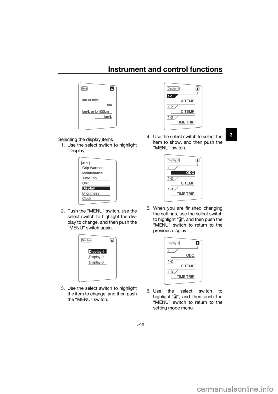
Selecting the display items
1. Use the select switch to highlight
“Display”.
2. Push the “MENU” switch, use the
select switch to highlight the dis-
play to change, and then push the
“MENU” switch again.
3. Use the select switch to highlight
the item to change, and then push
the “MENU” switch.4. Use the select switch to select the
item to show, and then push the
“MENU” switch.
5. When you are finished changing
the settings, use the select switch
to highlight “ ”, and then push the
“MENU” switch to return to the
previous display.
6. Use the select switch to
highlight “ ”, and then push the
“MENU” switch to return to the
setting mode menu.
Unit
km or mile
km
km/L or L/100km
km/L
MENU
Grip Warmer
Maintenance
Time Trip
Unit
Display
Brightness
Clock
Display
Display-1
Display-2
Display-3
Display-1
1-1
A.TEMP
1-2
C.TEMP
1-3
TIME TRIP
Display-1
1-1
ODO
1-2
C.TEMP
1-3
TIME TRIP
Display-1
1-1
ODO
1-2
C.TEMP
1-3
TIME TRIP
UB96E2E0.book Page 19 Wednesday, September 18, 2019 10:21 AM
Page 34 of 122
Instrument and control functions
3-20
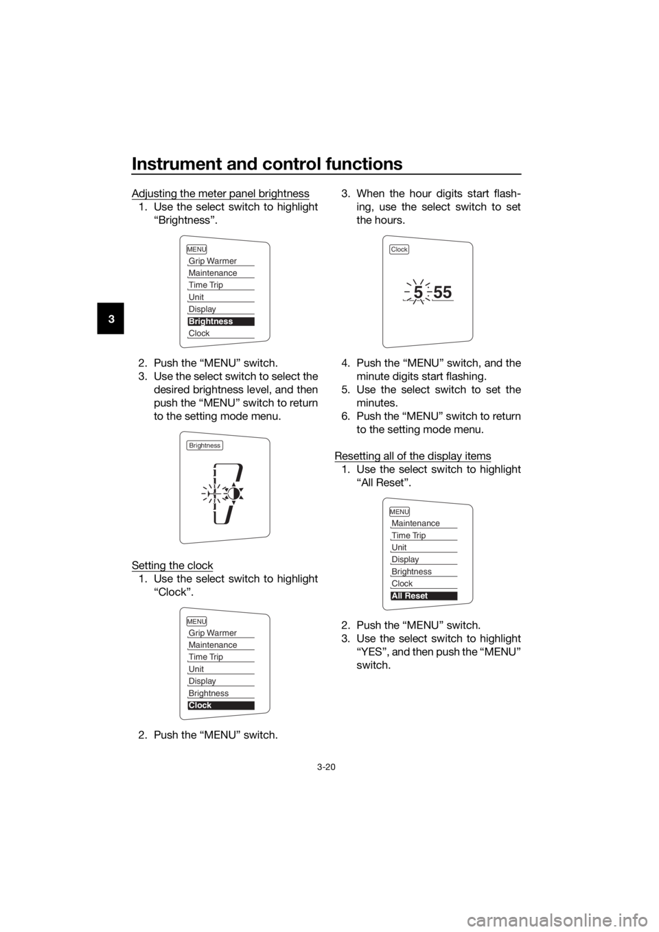
3Adjusting the meter panel brightness
1. Use the select switch to highlight
“Brightness”.
2. Push the “MENU” switch.
3. Use the select switch to select the
desired brightness level, and then
push the “MENU” switch to return
to the setting mode menu.
Setting the clock
1. Use the select switch to highlight
“Clock”.
2. Push the “MENU” switch.3. When the hour digits start flash-
ing, use the select switch to set
the hours.
4. Push the “MENU” switch, and the
minute digits start flashing.
5. Use the select switch to set the
minutes.
6. Push the “MENU” switch to return
to the setting mode menu.
Resetting all of the display items
1. Use the select switch to highlight
“All Reset”.
2. Push the “MENU” switch.
3. Use the select switch to highlight
“YES”, and then push the “MENU”
switch.
MENU
Grip Warmer
Maintenance
Time Trip
Unit
Display
Brightness
Clock
Brightness
MENU
Grip Warmer
Maintenance
Time Trip
Unit
Display
Brightness
Clock
Clock
555
MENU
Maintenance
Time Trip
Unit
Display
Brightness
Clock
All Reset
UB96E2E0.book Page 20 Wednesday, September 18, 2019 10:21 AM
Page 37 of 122
Instrument and control functions
3-23
3
EAU12781Cruise control switches
See page 3-6 for an explanation of the
cruise control system.
EAU54232Menu switch “MENU”
This switch is used to make setting
changes within the multi-function me-
ter unit. (See page 3-9.)
EAU54222Select switch “ / ”
This switch is used to make setting
changes within the multi-function me-
ter unit. (See page 3-9.)
EAU54691Drive mode switch “MODE”
WARNING
EWA15341
Do not change the D-mode while the
vehicle is moving.
Using this switch changes the drive
mode to touring mode “T” or sports
mode “S”.
The throttle grip must be completely
closed in order to change the drive mo-
de.
The selected mode is shown on the
drive mode display. (See page 3-11.)
The drive mode cannot be changed
while the cruise control system is oper-
ating.
EAU12834
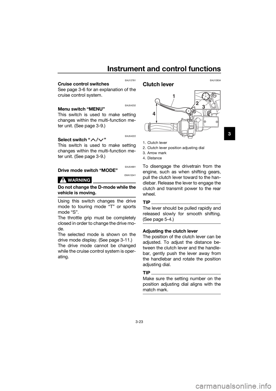
Clutch lever
To disengage the drivetrain from the
engine, such as when shifting gears,
pull the clutch lever toward to the han-
dlebar. Release the lever to engage the
clutch and transmit power to the rear
wheel.
TIP
The lever should be pulled rapidly and
released slowly for smooth shifting.
(See page 5-4.)
Adjusting the clutch lever
The position of the clutch lever can be
adjusted. To adjust the distance be-
tween the clutch lever and the handle-
bar, gently push the lever away from
the handlebar and rotate the position
adjusting dial.
TIP
Make sure the setting number on the
position adjusting dial aligns with the
match mark.
1. Clutch lever
2. Clutch lever position adjusting dial
3. Arrow mark
4. Distance
15432
41
2
3
UB96E2E0.book Page 23 Wednesday, September 18, 2019 10:21 AM
Page 54 of 122
Instrument and control functions
3-40
3• The suspension will still operate
as normal, only the preload ad-
justing function cannot be used.
• To reset the suspension system
warning light, wait approximate-
ly 6 minutes and then turn the
main switch off or immediately
turn the main switch off and
then wait 6 minutes.
• If the suspension system warn-
ing light remains on, have a
Yamaha dealer check the vehi-
cle.
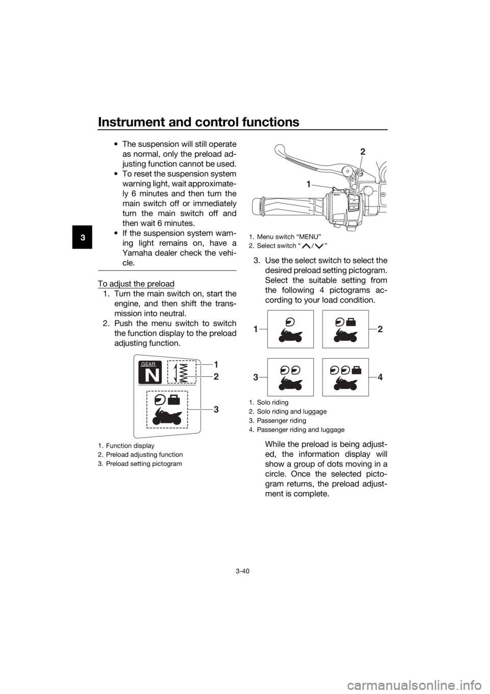
To adjust the preload
1. Turn the main switch on, start the
engine, and then shift the trans-
mission into neutral.
2. Push the menu switch to switch
the function display to the preload
adjusting function.3. Use the select switch to select the
desired preload setting pictogram.
Select the suitable setting from
the following 4 pictograms ac-
cording to your load condition.
While the preload is being adjust-
ed, the information display will
show a group of dots moving in a
circle. Once the selected picto-
gram returns, the preload adjust-
ment is complete.
1. Function display
2. Preload adjusting function
3. Preload setting pictogram
GEAR
N
1
3
2
1. Menu switch “MENU”
2. Select switch “ / ”
1. Solo riding
2. Solo riding and luggage
3. Passenger riding
4. Passenger riding and luggage
1
2
12
34
UB96E2E0.book Page 40 Wednesday, September 18, 2019 10:21 AM
Page 55 of 122
Instrument and control functions
3-41
3
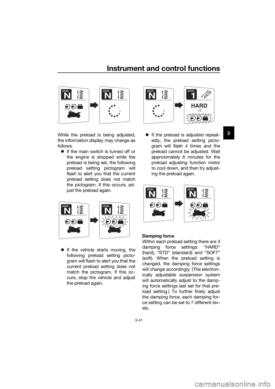
While the preload is being adjusted,
the information display may change as
follows.
If the main switch is turned off or
the engine is stopped while the
preload is being set, the following
preload setting pictogram will
flash to alert you that the current
preload setting does not match
the pictogram. If this occurs, ad-
just the preload again.
If the vehicle starts moving, the
following preload setting picto-
gram will flash to alert you that the
current preload setting does not
match the pictogram. If this oc-
curs, stop the vehicle and adjust
the preload again.If the preload is adjusted repeat-
edly, the preload setting picto-
gram will flash 4 times and the
preload cannot be adjusted. Wait
approximately 6 minutes for the
preload adjusting function motor
to cool down, and then try adjust-
ing the preload again.
Damping force
Within each preload setting there are 3
damping force settings: “HARD”
(hard), “STD” (standard) and “SOFT”
(soft). When the preload setting is
changed, the damping force settings
will change accordingly. (The electron-
ically adjustable suspension system
will automatically adjust to the damp-
ing force settings last set for that pre-
load setting.) To further finely adjust
the damping force, each damping for-
ce setting can be set to 7 different lev-
els.
GEAR
N
GEAR
N
GEAR
N
GEAR
N
GEAR
1
HARD+3
GEAR
N
GEAR
N
GEAR
N
UB96E2E0.book Page 41 Wednesday, September 18, 2019 10:21 AM
Page 56 of 122
Instrument and control functions
3-42
3
TIP
If the preload setting was not complet-
ed correctly:
The damping force setting and
setting level will flash 4 times and
cannot be adjusted if you try to
adjust them while the vehicle is
stopped.
The preload setting pictogram will
flash and the damping force can-
not be adjusted if you try to adjust
it while the vehicle is moving.
Be sure that the preload has been set
correctly before adjusting the damping
force.
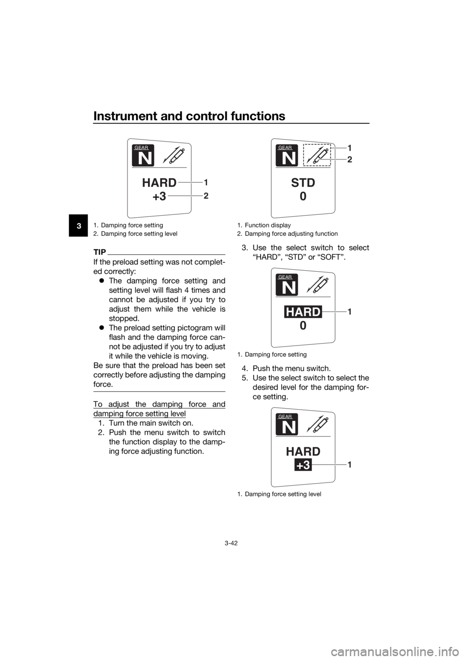
To adjust the damping force and
damping force setting level
1. Turn the main switch on.
2. Push the menu switch to switch
the function display to the damp-
ing force adjusting function.3. Use the select switch to select
“HARD”, “STD” or “SOFT”.
4. Push the menu switch.
5. Use the select switch to select the
desired level for the damping for-
ce setting.
1. Damping force setting
2. Damping force setting level
GEAR
N
HARD
+3
2
1
1. Function display
2. Damping force adjusting function
1. Damping force setting
1. Damping force setting level
GEAR
N
STD
0
1
2
GEAR
N
HARD
01
GEAR
N
HARD
+31
UB96E2E0.book Page 42 Wednesday, September 18, 2019 10:21 AM
Page 57 of 122
Instrument and control functions
3-43
3
TIP
The damping force setting can be set to
7 levels (+3, +2, +1, 0, –1, –2 and –3).
“+3” is the hardest level and “–3” is the
softest level.
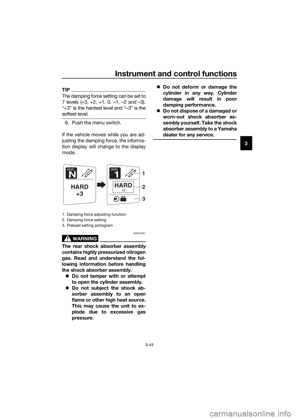
6. Push the menu switch.
If the vehicle moves while you are ad-
justing the damping force, the informa-
tion display will change to the display
mode.
WARNING
EWA16421
The rear shock absorber assembly
contains highly pressurized nitrogen
gas. Read and understand the fol-
lowing information before handling
the shock absorber assembly.
Do not tamper with or attempt
to open the cylinder assembly.
Do not subject the shock ab-
sorber assembly to an open
flame or other high heat source.
This may cause the unit to ex-
plode due to excessive gas
pressure.Do not deform or damage the
cylinder in any way. Cylinder
damage will result in poor
damping performance.
Do not dispose of a damaged or
worn-out shock ab
sorber as-
sembly yourself. Take the shock
absorber assembly to a Yamaha
dealer for any service.
1. Damping force adjusting function
2. Damping force setting
3. Preload setting pictogram
GEAR
N
HARD
+3
GEAR
1
HARD+3
1
2
3
UB96E2E0.book Page 43 Wednesday, September 18, 2019 10:21 AM