key YAMAHA FJR1300AE 2020 User Guide
[x] Cancel search | Manufacturer: YAMAHA, Model Year: 2020, Model line: FJR1300AE, Model: YAMAHA FJR1300AE 2020Pages: 122, PDF Size: 3.93 MB
Page 36 of 122
Instrument and control functions
3-22
3
EAU1234M
Handlebar switches
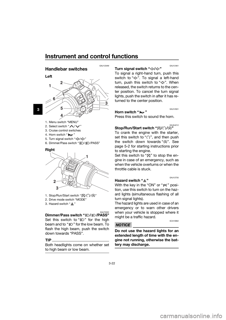
Left
Right
EAU73022Dimmer/Pass switch “ / /PASS”
Set this switch to “ ” for the high
beam and to “ ” for the low beam. To
flash the high beam, push the switch
down towards “PASS”.
TIP
Both headlights come on whether set
to high beam or low beam.
EAU12461Turn signal switch “ / ”
To signal a right-hand turn, push this
switch to “ ”. To signal a left-hand
turn, push this switch to “ ”. When
released, the switch returns to the cen-
ter position. To cancel the turn signal
lights, push the switch in after it has re-
turned to the center position.
EAU12501Horn switch “ ”
Press this switch to sound the horn.
EAU54212Stop/Run/Start switch “ / / ”
To crank the engine with the starter,
set this switch to “ ”, and then push
the switch down towards “ ”. See
page 5-2 for starting instructions prior
to starting the engine.
Set this switch to “ ” to stop the en-
gine in case of an emergency, such as
when the vehicle overturns or when the
throttle cable is stuck.
EAU12735Hazard switch “ ”
With the key in the “ON” or “ ” posi-
tion, use this switch to turn on the haz-
ard lights (simultaneous flashing of all
turn signal lights).
The hazard lights are used in case of an
emergency or to warn other drivers
when your vehicle is stopped where it
might be a traffic hazard.
NOTICE
ECA10062
Do not use the hazard lights for an
extended length of time with the en-
gine not running, otherwise the bat-
tery may discharge.
1. Menu switch “MENU”
2. Select switch “ / ”
3. Cruise control switches
4. Horn switch “ ”
5. Turn signal switch “ / ”
6. Dimmer/Pass switch “ / /PASS”
1. Stop/Run/Start switch “ / / ”
2. Drive mode switch “MODE”
3. Hazard switch “ ”
RES
SETPA SS
1
6
5
4
2
3
STOP
M
O
D
E
RUNSTART
3
2
1
UB96E2E0.book Page 22 Wednesday, September 18, 2019 10:21 AM
Page 39 of 122
Instrument and control functions
3-25
3
EAU39542
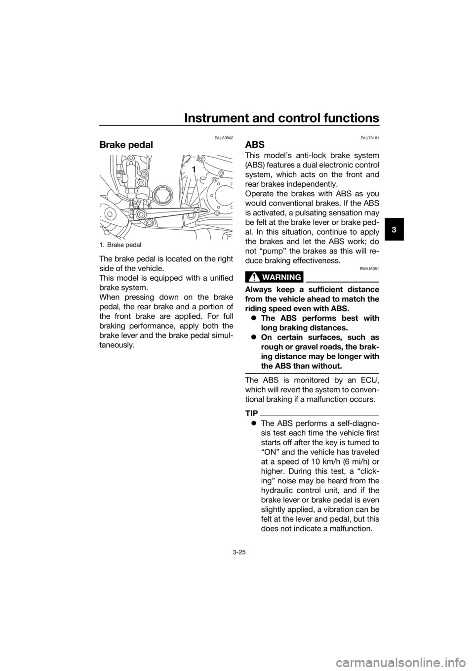
Brake pedal
The brake pedal is located on the right
side of the vehicle.
This model is equipped with a unified
brake system.
When pressing down on the brake
pedal, the rear brake and a portion of
the front brake are applied. For full
braking performance, apply both the
brake lever and the brake pedal simul-
taneously.
EAU73181
ABS
This model’s anti-lock brake system
(ABS) features a dual electronic control
system, which acts on the front and
rear brakes independently.
Operate the brakes with ABS as you
would conventional brakes. If the ABS
is activated, a pulsating sensation may
be felt at the brake lever or brake ped-
al. In this situation, continue to apply
the brakes and let the ABS work; do
not “pump” the brakes as this will re-
duce braking effectiveness.
WARNING
EWA16051
Always keep a sufficient distance
from the vehicle ahead to match the
riding speed even with ABS.
The ABS performs best with
long braking distances.
On certain surfaces, such as
rough or gravel roads, the brak-
ing distance may be longer with
the ABS than without.
The ABS is monitored by an ECU,
which will revert the system to conven-
tional braking if a malfunction occurs.
TIP
The ABS performs a self-diagno-
sis test each time the vehicle first
starts off after the key is turned to
“ON” and the vehicle has traveled
at a speed of 10 km/h (6 mi/h) or
higher. During this test, a “click-
ing” noise may be heard from the
hydraulic control unit, and if the
brake lever or brake pedal is even
slightly applied, a vibration can be
felt at the lever and pedal, but this
does not indicate a malfunction.
1. Brake pedal
1
UB96E2E0.book Page 25 Wednesday, September 18, 2019 10:21 AM
Page 42 of 122
Instrument and control functions
3-28
3
EAU13077
Fuel tank cap
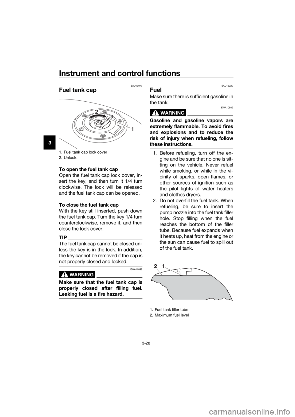
To open the fuel tank cap
Open the fuel tank cap lock cover, in-
sert the key, and then turn it 1/4 turn
clockwise. The lock will be released
and the fuel tank cap can be opened.
To close the fuel tank cap
With the key still inserted, push down
the fuel tank cap. Turn the key 1/4 turn
counterclockwise, remove it, and then
close the lock cover.
TIP
The fuel tank cap cannot be closed un-
less the key is in the lock. In addition,
the key cannot be removed if the cap is
not properly closed and locked.
WARNING
EWA11092
Make sure that the fuel tank cap is
properly closed after filling fuel.
Leaking fuel is a fire hazard.
EAU13222
Fuel
Make sure there is sufficient gasoline in
the tank.
WARNING
EWA10882
Gasoline and gasoline vapors are
extremely flammable. To avoid fires
and explosions and to reduce the
risk of injury when refueling, follow
these instructions.
1. Before refueling, turn off the en-
gine and be sure that no one is sit-
ting on the vehicle. Never refuel
while smoking, or while in the vi-
cinity of sparks, open flames, or
other sources of ignition such as
the pilot lights of water heaters
and clothes dryers.
2. Do not overfill the fuel tank. When
refueling, be sure to insert the
pump nozzle into the fuel tank filler
hole. Stop filling when the fuel
reaches the bottom of the filler
tube. Because fuel expands when
it heats up, heat from the engine or
the sun can cause fuel to spill out
of the fuel tank.1. Fuel tank cap lock cover
2. Unlock.
1 2
1. Fuel tank filler tube
2. Maximum fuel level
21
UB96E2E0.book Page 28 Wednesday, September 18, 2019 10:21 AM
Page 45 of 122
Instrument and control functions
3-31
3
EAU39496
Seats
Passenger seat
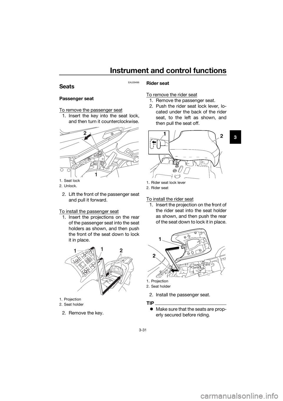
To remove the passenger seat
1. Insert the key into the seat lock,
and then turn it counterclockwise.
2. Lift the front of the passenger seat
and pull it forward.
To install the passenger seat
1. Insert the projections on the rear
of the passenger seat into the seat
holders as shown, and then push
the front of the seat down to lock
it in place.
2. Remove the key.Rider seat
To remove the rider seat
1. Remove the passenger seat.
2. Push the rider seat lock lever, lo-
cated under the back of the rider
seat, to the left as shown, and
then pull the seat off.
To install the rider seat
1. Insert the projection on the front of
the rider seat into the seat holder
as shown, and then push the rear
of the seat down to lock it in place.
2. Install the passenger seat.
TIP
Make sure that the seats are prop-
erly secured before riding.
1. Seat lock
2. Unlock.
1. Projection
2. Seat holder
1 2
1. Rider seat lock lever
2. Rider seat
1. Projection
2. Seat holder
UB96E2E0.book Page 31 Wednesday, September 18, 2019 10:21 AM
Page 49 of 122
Instrument and control functions
3-35
3 Do not subject the IMU to
strong shocks or moisture.
Do not obstruct the IMU breath-
er hole and do not clean it with
compressed air.
When storing documents or other
items in a storage compartment, be
sure to wrap them in a plastic bag so
that they will not get wet. When wash-
ing the vehicle, be careful not to let any
water enter a storage compartment.
WARNING
EWA14421
Do not exceed the load limit of 1
kg (2 lb) for storage compart-
ment A.
Do not exceed the load limit of 3
kg (7 lb) for storage compart-
ment B.
Do not exceed the maximum
load of 212 kg (467 lb) for the ve-
hicle.
EAU39482
Accessory box
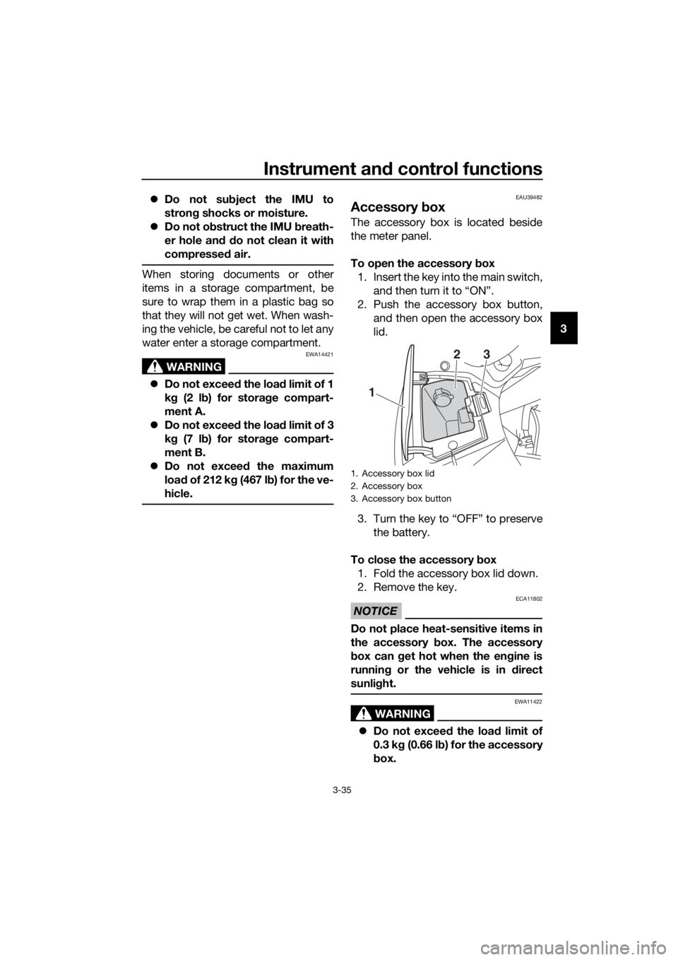
The accessory box is located beside
the meter panel.
To open the accessory box
1. Insert the key into the main switch,
and then turn it to “ON”.
2. Push the accessory box button,
and then open the accessory box
lid.
3. Turn the key to “OFF” to preserve
the battery.
To close the accessory box
1. Fold the accessory box lid down.
2. Remove the key.
NOTICE
ECA11802
Do not place heat-sensitive items in
the accessory box. The accessory
box can get hot when the engine is
running or the vehicle is in direct
sunlight.
WARNING
EWA11422
Do not exceed the load limit of
0.3 kg (0.66 lb) for the accessory
box.
1. Accessory box lid
2. Accessory box
3. Accessory box button
1
23
UB96E2E0.book Page 35 Wednesday, September 18, 2019 10:21 AM
Page 58 of 122
Instrument and control functions
3-44
3
EAU39657
Auxiliary DC jack
WARNING
EWA14361
To prevent electrical shock or short-
circuiting, make sure that the cap is
installed when the auxiliary DC jack
is not being used.
NOTICE
ECA15432
The accessory connected to the
auxiliary DC jack should not be used
with the engine turned off, and the
load must never exceed 30 W (2.5 A),
otherwise the fuse may blow or the
battery may discharge.
This vehicle is equipped with an auxil-
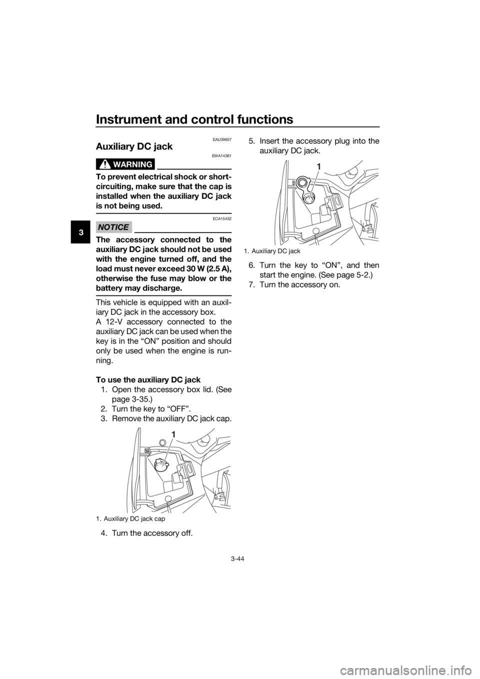
iary DC jack in the accessory box.
A 12-V accessory connected to the
auxiliary DC jack can be used when the
key is in the “ON” position and should
only be used when the engine is run-
ning.
To use the auxiliary DC jack
1. Open the accessory box lid. (See
page 3-35.)
2. Turn the key to “OFF”.
3. Remove the auxiliary DC jack cap.
4. Turn the accessory off.5. Insert the accessory plug into the
auxiliary DC jack.
6. Turn the key to “ON”, and then
start the engine. (See page 5-2.)
7. Turn the accessory on.
1. Auxiliary DC jack cap
1
1. Auxiliary DC jack
1
UB96E2E0.book Page 44 Wednesday, September 18, 2019 10:21 AM
Page 69 of 122
Operation and important riding points
5-6
5
EAU17214
Parking
When parking, stop the engine, and
then remove the key from the main
switch.
WARNING
EWA10312
Since the engine and exhaust
system can become very hot,
park in a place where pedestri-
ans or children are not likely to
touch them and be burned.
Do not park on a slope or on soft
ground, otherwise the vehicle
may overturn, increasing the
risk of a fuel leak and fire.
Do not park near grass or other
flammable materials which
might catch fire.
UB96E2E0.book Page 6 Wednesday, September 18, 2019 10:21 AM
Page 103 of 122
Periodic maintenance and adjustment
6-34
6
EAU54515
Replacing the fuses
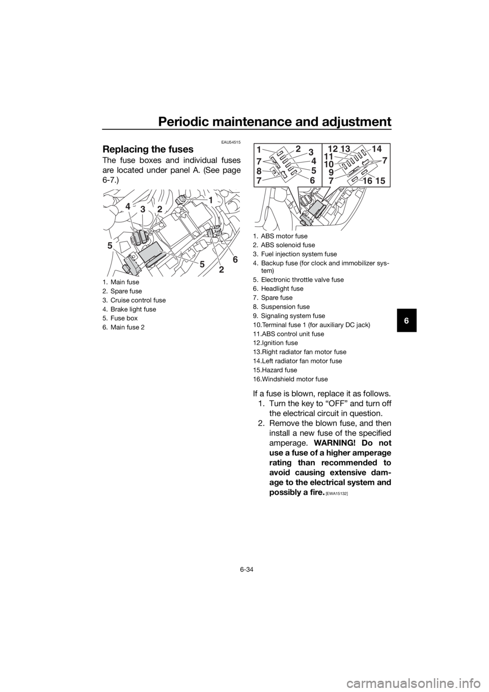
The fuse boxes and individual fuses
are located under panel A. (See page
6-7.)
If a fuse is blown, replace it as follows.
1. Turn the key to “OFF” and turn off
the electrical circuit in question.
2. Remove the blown fuse, and then
install a new fuse of the specified
amperage. WARNING! Do not
use a fuse of a higher amperage
rating than recommended to
avoid causing extensive dam-
age to the electrical system and
possibly a fire.
[EWA15132]
1. Main fuse
2. Spare fuse
3. Cruise control fuse
4. Brake light fuse
5. Fuse box
6. Main fuse 2
5
1
3 4
2
5
26
1. ABS motor fuse
2. ABS solenoid fuse
3. Fuel injection system fuse
4. Backup fuse (for clock and immobilizer sys-
tem)
5. Electronic throttle valve fuse
6. Headlight fuse
7. Spare fuse
8. Suspension fuse
9. Signaling system fuse
10.Terminal fuse 1 (for auxiliary DC jack)
11.ABS control unit fuse
12.Ignition fuse
13.Right radiator fan motor fuse
14.Left radiator fan motor fuse
15.Hazard fuse
16.Windshield motor fuse
8
1
7
23
4
5
6
7
14
710
9111213
71615
UB96E2E0.book Page 34 Wednesday, September 18, 2019 10:21 AM
Page 104 of 122
Periodic maintenance and adjustment
6-35
6
3. Turn the key to “ON” and turn on
the electrical circuit in question to
check if the device operates.
4. If the fuse immediately blows
again, have a Yamaha dealer
check the electrical system.
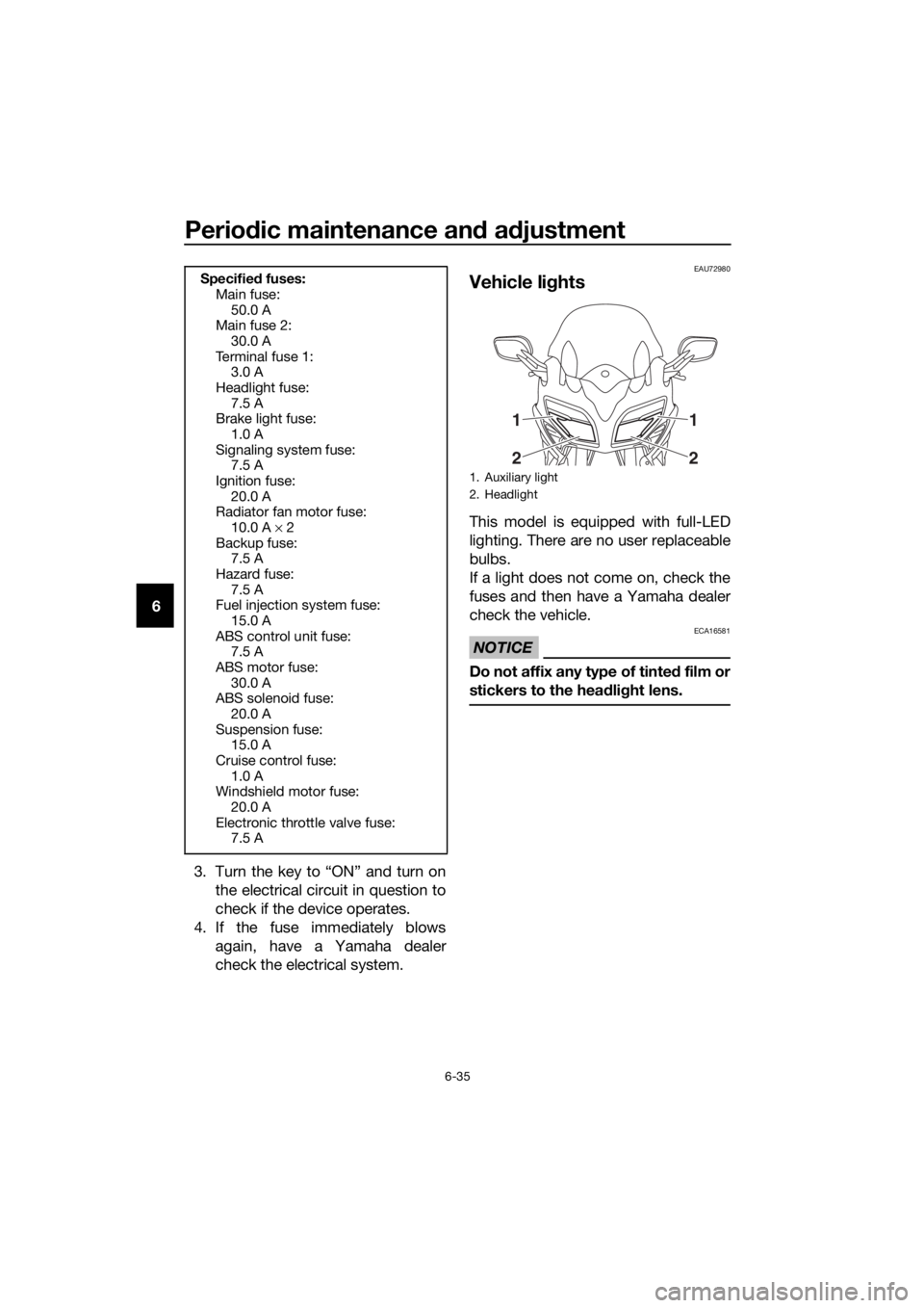
EAU72980
Vehicle lights
This model is equipped with full-LED
lighting. There are no user replaceable
bulbs.
If a light does not come on, check the
fuses and then have a Yamaha dealer
check the vehicle.
NOTICE
ECA16581
Do not affix any type of tinted film or
stickers to the headlight lens.
Specified fuses:
Main fuse:
50.0 A
Main fuse 2:
30.0 A
Te r m i n a l f u s e 1 :
3.0 A
Headlight fuse:
7.5 A
Brake light fuse:
1.0 A
Signaling system fuse:
7.5 A
Ignition fuse:
20.0 A
Radiator fan motor fuse:
10.0 A × 2
Backup fuse:
7.5 A
Hazard fuse:
7.5 A
Fuel injection system fuse:
15.0 A
ABS control unit fuse:
7.5 A
ABS motor fuse:
30.0 A
ABS solenoid fuse:
20.0 A
Suspension fuse:
15.0 A
Cruise control fuse:
1.0 A
Windshield motor fuse:
20.0 A
Electronic throttle valve fuse:
7.5 A
1. Auxiliary light
2. Headlight
1
21
2
UB96E2E0.book Page 35 Wednesday, September 18, 2019 10:21 AM