seat adjustment YAMAHA FJR1300AE 2020 Owners Manual
[x] Cancel search | Manufacturer: YAMAHA, Model Year: 2020, Model line: FJR1300AE, Model: YAMAHA FJR1300AE 2020Pages: 122, PDF Size: 3.93 MB
Page 5 of 122

Table of contents
Safety information............................1-1
Description........................................2-1
Left view ..........................................2-1
Right view........................................2-2
Controls and instruments ................2-3
Instrument and control functions....3-1
Immobilizer system .........................3-1
Main switch/steering lock ...............3-2
Indicator lights and warning
lights ............................................3-3
Cruise control system .....................3-6
Multi-function meter unit .................3-9
D-mode (drive mode) ....................3-21
Handlebar switches.......................3-22
Clutch lever ...................................3-23
Shift pedal .....................................3-24
Brake lever ....................................3-24
Brake pedal ...................................3-25
ABS ...............................................3-25
Traction control system.................3-26
Fuel tank cap.................................3-28
Fuel................................................3-28
Fuel tank overflow hose ................3-30
Catalytic converter ........................3-30
Seats .............................................3-31
Adjusting the rider seat height ......3-32
Storage compartments .................3-34
Accessory box...............................3-35
Adjusting the headlight beams......3-36
Handlebar position ........................3-37
Opening and closing the cowling
vents ..........................................3-37
Rear view mirrors ..........................3-39
Adjusting the front and rear
suspension.................................3-39
Auxiliary DC jack ..........................3-44
Sidestand ......................................3-45
Ignition circuit cut-off system........3-45
Cornering lights .............................3-47For your safety – pre-operation
checks............................................... 4-1
Operation and important riding
points................................................. 5-1
Engine break-in ............................... 5-1
Starting the engine.......................... 5-2
Shifting ............................................ 5-4
Tips for reducing fuel
consumption................................ 5-5
Parking ............................................ 5-6
Periodic maintenance and
adjustment........................................ 6-1
Tool kit ............................................ 6-2
Periodic maintenance charts .......... 6-3
Periodic maintenance chart for the
emission control system.............. 6-3
General maintenance and
lubrication chart........................... 6-4
Removing and installing panels ...... 6-7
Checking the spark plugs ............. 6-10
Canister......................................... 6-11
Engine oil and oil filter cartridge ... 6-11
Why Yamalube .............................. 6-14
Final gear oil.................................. 6-15
Coolant ......................................... 6-16
Cleaning the air filter element ....... 6-18
Checking the engine idling
speed......................................... 6-19
Checking the throttle grip free
play ............................................ 6-20
Valve clearance ............................. 6-20
Tires .............................................. 6-21
Cast wheels .................................. 6-23
Clutch lever ................................... 6-24
Checking the brake lever free
play ............................................ 6-24
Brake light switches ...................... 6-25
Checking the front and rear
brake pads................................. 6-25
Checking the brake and clutch
fluid levels .................................. 6-26
Changing the brake and clutch
fluids .......................................... 6-28
UB96E2E0.book Page 1 Wednesday, September 18, 2019 10:21 AM
Page 77 of 122

Periodic maintenance and adjustment
6-8
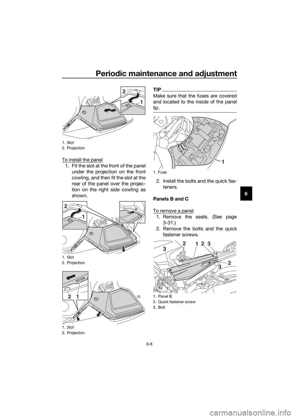
6 To install the panel
1. Fit the slot at the front of the panel
under the projection on the front
cowling, and then fit the slot at the
rear of the panel over the projec-
tion on the right side cowling as
shown.
TIP
Make sure that the fuses are covered
and located to the inside of the panel
lip.
2. Install the bolts and the quick fas-
teners.
Panels B and C
To remove a panel
1. Remove the seats. (See page
3-31.)
2. Remove the bolts and the quick
fastener screws.
1. Slot
2. Projection
1. Slot
2. Projection
1. Slot
2. Projection
2
1
2
1
12
1. Fuse
1. Panel B
2. Quick fastener screw
3. Bolt
1
12
2 3
3 2
3
UB96E2E0.book Page 8 Wednesday, September 18, 2019 10:21 AM
Page 78 of 122

Periodic maintenance and adjustment
6-9
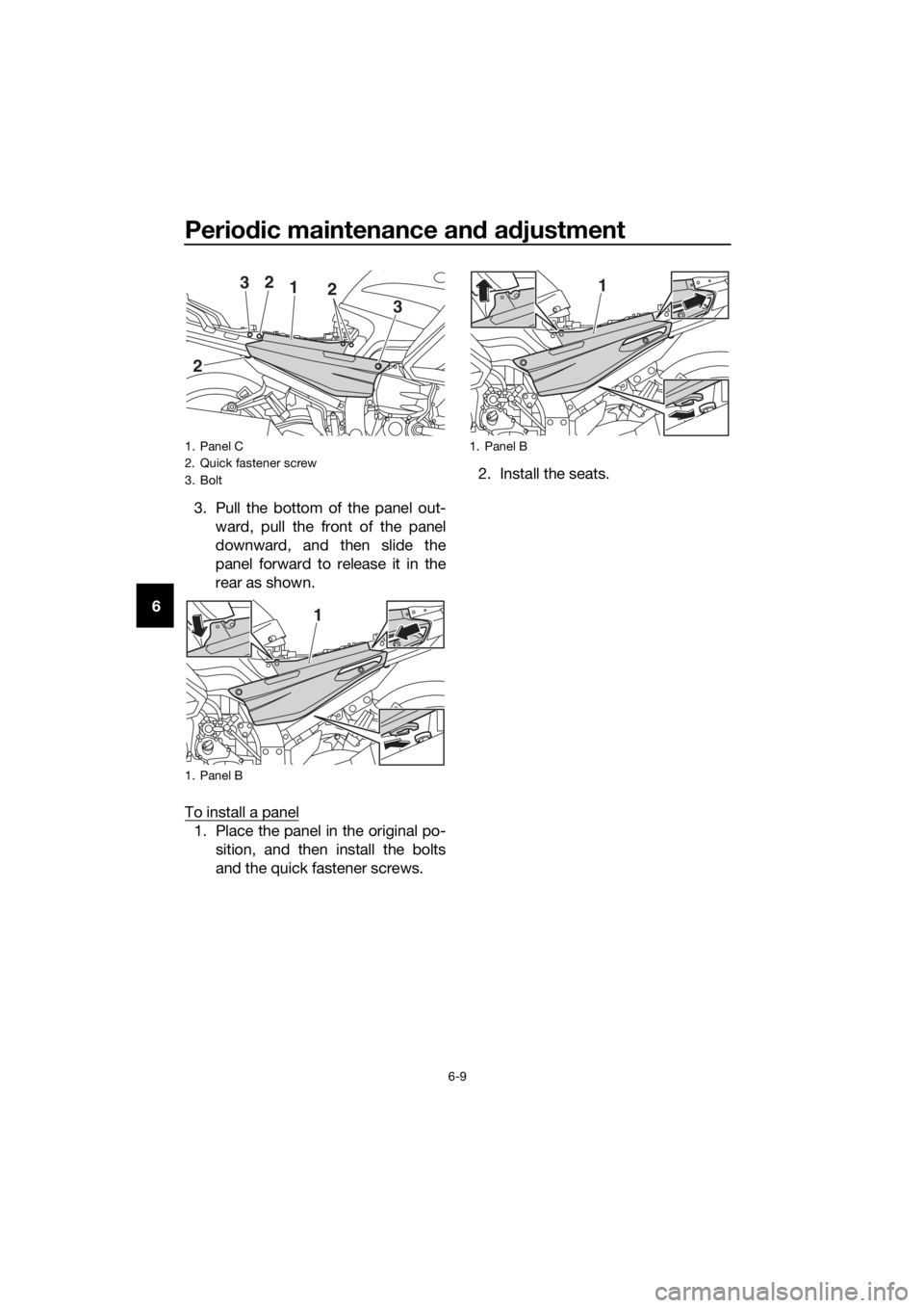
63. Pull the bottom of the panel out-
ward, pull the front of the panel
downward, and then slide the
panel forward to release it in the
rear as shown.
To install a panel
1. Place the panel in the original po-
sition, and then install the bolts
and the quick fastener screws.2. Install the seats.
1. Panel C
2. Quick fastener screw
3. Bolt
1. Panel B
12
2
23
3
1
1. Panel B
1
UB96E2E0.book Page 9 Wednesday, September 18, 2019 10:21 AM
Page 82 of 122

Periodic maintenance and adjustment
6-13
6
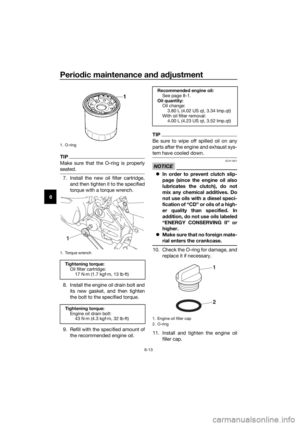
TIP
Make sure that the O-ring is properly
seated.
7. Install the new oil filter cartridge,
and then tighten it to the specified
torque with a torque wrench.
8. Install the engine oil drain bolt and
its new gasket, and then tighten
the bolt to the specified torque.
9. Refill with the specified amount of
the recommended engine oil.
TIP
Be sure to wipe off spilled oil on any
parts after the engine and exhaust sys-
tem have cooled down.
NOTICE
ECA11621
In order to prevent clutch slip-
page (since the engine oil also
lubricates the clutch), do not
mix any chemical additives. Do
not use oils with a diesel speci-
fication of “CD” or oils of a high-
er quality than specified. In
addition, do not use oils labeled
“ENERGY CONSERVING II” or
higher.
Make sure that no foreign mate-
rial enters the crankcase.
10. Check the O-ring for damage, and
replace it if necessary.
11. Install and tighten the engine oil
filler cap.
1. O-ring
1. Torque wrench
Tightening torque:
Oil filter cartridge:
17 N·m (1.7 kgf·m, 13 lb·ft)
Tightening torque:
Engine oil drain bolt:
43 N·m (4.3 kgf·m, 32 lb·ft)
1
Recommended engine oil:
See page 8-1.
Oil quantity:
Oil change:
3.80 L (4.02 US qt, 3.34 Imp.qt)
With oil filter removal:
4.00 L (4.23 US qt, 3.52 Imp.qt)
1. Engine oil filler cap
2. O-ring
2
1
UB96E2E0.book Page 13 Wednesday, September 18, 2019 10:21 AM
Page 87 of 122

Periodic maintenance and adjustment
6-18
6
EAU72990
Cleaning the air filter element
The air filter element should be cleaned
or replaced at the intervals specified in
the periodic maintenance and lubrica-
tion chart. Clean or, if necessary, re-
place the air filter element more
frequently if you are riding in unusually
wet or dusty areas.
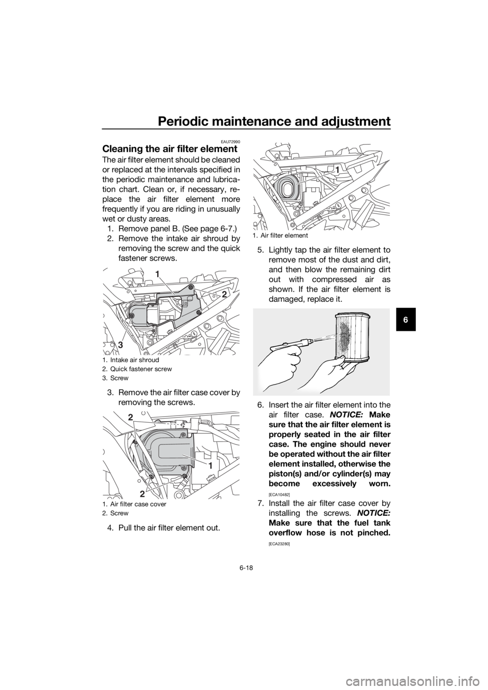
1. Remove panel B. (See page 6-7.)
2. Remove the intake air shroud by
removing the screw and the quick
fastener screws.
3. Remove the air filter case cover by
removing the screws.
4. Pull the air filter element out.5. Lightly tap the air filter element to
remove most of the dust and dirt,
and then blow the remaining dirt
out with compressed air as
shown. If the air filter element is
damaged, replace it.
6. Insert the air filter element into the
air filter case. NOTICE: Make
sure that the air filter element is
properly seated in the air filter
case. The engine should never
be operated without the air filter
element installed, otherwise the
piston(s) and/or cylinder(s) may
become excessively worn.
[ECA10482]
7. Install the air filter case cover by
installing the screws. NOTICE:
Make sure that the fuel tank
overflow hose is not pinched.
[ECA23280]
1. Intake air shroud
2. Quick fastener screw
3. Screw
1. Air filter case cover
2. Screw
1
3
2
2
21
1. Air filter element
1
UB96E2E0.book Page 18 Wednesday, September 18, 2019 10:21 AM