coolant temperature YAMAHA FJR1300AS 2013 Owners Manual
[x] Cancel search | Manufacturer: YAMAHA, Model Year: 2013, Model line: FJR1300AS, Model: YAMAHA FJR1300AS 2013Pages: 122, PDF Size: 3.34 MB
Page 29 of 122

INSTRUMENT AND CONTROL FUNCTIONS
3-14
3
Push the menu switch “MENU” to
switch the display between the follow-
ing functions. The display changes
each time the switch is pushed.
●
Grip warmer adjusting function
●
Information display selection func-
tion
●
Windshield adjusting function
●
Damping force adjusting function
●
Preload adjusting function
TIPThe preload adjusting function will ap-
pear only when the vehicle is stopped
with the engine running.The following pages contain explana-
tion of the grip warmer, information dis-
play, and windshield functions. See
page 3-42 for an explanation of the pre-
load and damping force adjusting func-
tions.
Adjusting the grip warmerThis vehicle is equipped with grip
warmers, which can only be used when
the engine is running. There are 4 grip
warmer settings. To increase the grip warmer tempera-
ture, push the “ ” side of the select
switch. To decrease the grip warmer
temperature, push the “ ” side of the
select switch.
NOTICE
ECA17930
●
Be sure to wear gloves when us-
ing the grip warmers.
●
If the ambient temperature is 20
°C (68 °F) or higher, do not set
the grip warmer to the high set-
ting.
●
If the handlebar grip or throttle
grip becomes worn or damaged,
stop using the grip warmers and
replace the grips.
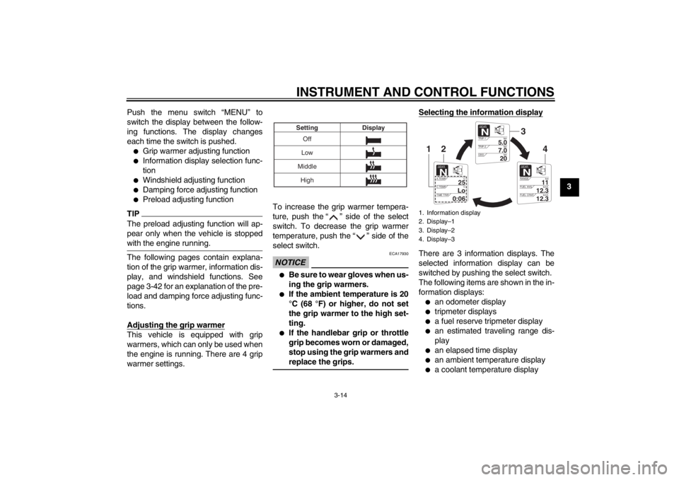
Selecting the information displayThere are 3 information displays. The
selected information display can be
switched by pushing the select switch.
The following items are shown in the in-
formation displays:●
an odometer display
●
tripmeter displays
●
a fuel reserve tripmeter display
●
an estimated traveling range dis-
play
●
an elapsed time display
●
an ambient temperature display
●
a coolant temperature display
Off
Low
Middle Display
Setting
High
1. Information display
2. Display–1
3. Display–2
4. Display–3
GEARN
5.0
TRIP-1 km
7.0
TRIP-2km
km
20
ODO
GEARN
11
RANGE km
12.3
FUEL AVG km/L
km/L
12.3
FUEL CRNT
GEARN
25
A.TEMP ˚C
Lo
C.TEMP ˚C
0:06
TIME TRIP
3
4
2
1
U1MDE0E0.book Page 14 Friday, February 15, 2013 1:26 PM
Page 31 of 122

INSTRUMENT AND CONTROL FUNCTIONS
3-16
3
This display is automatically reset when
the key is turned to “OFF”.
TIPThere are also “TIME–2” and “TIME–3”
elapsed time displays, but they cannot
be set to the information display. See
“Setting mode” on page 3-18 for de-
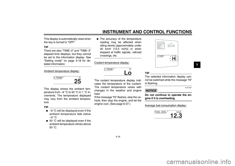
tailed information.Ambient temperature display:This display shows the ambient tem-
perature from –9 °C to 50 °C in 1 °C in-
crements. The temperature displayed
may vary from the ambient tempera-
ture.TIP●
–9 °C will be displayed even if the
ambient temperature falls below
–9 °C.
●
50 °C will be displayed even if the
ambient temperature climbs above
50 °C.
●
The accuracy of the temperature
reading may be affected when
riding slowly [approximately under
20 km/h (12.5 mi/h)] or when
stopped at traffic signals, railroad
crossings, etc.
Coolant temperature display:The coolant temperature display indi-
cates the temperature of the coolant.
The coolant temperature varies with
changes in the weather and engine
load.
If the message “Hi” flashes, stop the ve-
hicle, then stop the engine, and let the
engine cool. (See page 6-37.)
TIPThe selected information display can-
not be switched while the message “Hi”
is flashing.NOTICE
ECA10021
Do not continue to operate the en-
gine if it is overheating.Average fuel consumption display:
25
A.TEMP
˚C
Lo
C.TEMP˚C
GEAR4
Hi
C.TEMP˚C
12.3
FUEL AVG km/L
U1MDE0E0.book Page 16 Friday, February 15, 2013 1:26 PM
Page 88 of 122

PERIODIC MAINTENANCE AND ADJUSTMENT
6-16
6
EAU20070
Coolant The coolant level should be checked
before each ride. In addition, the cool-
ant must be changed at the intervals
specified in the periodic maintenance
and lubrication chart.
EAU54160
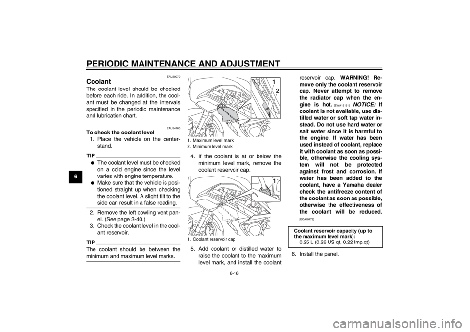
To check the coolant level1. Place the vehicle on the center- stand.TIP●
The coolant level must be checked
on a cold engine since the level
varies with engine temperature.
●
Make sure that the vehicle is posi-
tioned straight up when checking
the coolant level. A slight tilt to the
side can result in a false reading.
2. Remove the left cowling vent pan-el. (See page 3-40.)
3. Check the coolant level in the cool- ant reservoir.TIPThe coolant should be between the
minimum and maximum level marks.
4. If the coolant is at or below theminimum level mark, remove the
coolant reservoir cap.
5. Add coolant or distilled water to raise the coolant to the maximum
level mark, and install the coolant reservoir cap. WARNING! Re-
move only the coolant reservoir
cap. Never attempt to remove
the radiator cap when the en-
gine is hot.
[EWA15161]
NOTICE: If
coolant is not available, use dis-
tilled water or soft tap water in-
stead. Do not use hard water or
salt water since it is harmful to
the engine. If water has been
used instead of coolant, replace
it with coolant as soon as possi-
ble, otherwise the cooling sys-
tem will not be protected
against frost and corrosion. If
water has been added to the
coolant, have a Yamaha dealer
check the antifreeze content of
the coolant as soon as possible,
otherwise the effectiveness of
the coolant will be reduced.
[ECA10472]
6. Install the panel.
1. Maximum level mark
2. Minimum level mark
1. Coolant reservoir cap
1
21
Coolant reservoir capacity (up to
the maximum level mark): 0.25 L (0.26 US qt, 0.22 Imp.qt)
U1MDE0E0.book Page 16 Friday, February 15, 2013 1:26 PM