lights YAMAHA FJR1300AS 2015 Owners Manual
[x] Cancel search | Manufacturer: YAMAHA, Model Year: 2015, Model line: FJR1300AS, Model: YAMAHA FJR1300AS 2015Pages: 124, PDF Size: 3.39 MB
Page 6 of 124
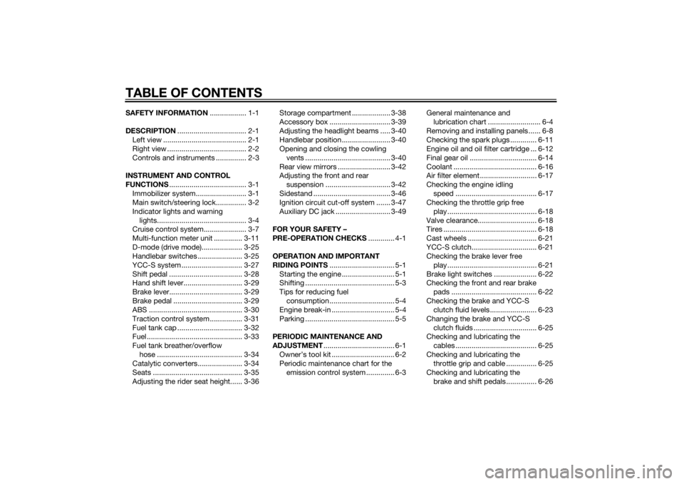
TABLE OF CONTENTSSAFETY INFORMATION.................. 1-1
DESCRIPTION.................................. 2-1
Left view ......................................... 2-1
Right view ....................................... 2-2
Controls and instruments ............... 2-3
INSTRUMENT AND CONTROL
FUNCTIONS...................................... 3-1
Immobilizer system......................... 3-1
Main switch/steering lock............... 3-2
Indicator lights and warning
lights............................................ 3-4
Cruise control system..................... 3-7
Multi-function meter unit .............. 3-11
D-mode (drive mode).................... 3-25
Handlebar switches ...................... 3-25
YCC-S system .............................. 3-27
Shift pedal .................................... 3-28
Hand shift lever............................. 3-29
Brake lever.................................... 3-29
Brake pedal .................................. 3-29
ABS .............................................. 3-30
Traction control system ................ 3-31
Fuel tank cap ................................ 3-32
Fuel ............................................... 3-33
Fuel tank breather/overflow
hose .......................................... 3-34
Catalytic converters...................... 3-34
Seats ............................................ 3-35
Adjusting the rider seat height...... 3-36Storage compartment ................... 3-38
Accessory box .............................. 3-39
Adjusting the headlight beams ..... 3-40
Handlebar position ........................ 3-40
Opening and closing the cowling
vents .......................................... 3-40
Rear view mirrors .......................... 3-42
Adjusting the front and rear
suspension ................................ 3-42
Sidestand ...................................... 3-46
Ignition circuit cut-off system ....... 3-47
Auxiliary DC jack ........................... 3-49
FOR YOUR SAFETY –
PRE-OPERATION CHECKS............. 4-1
OPERATION AND IMPORTANT
RIDING POINTS................................ 5-1
Starting the engine .......................... 5-1
Shifting ............................................ 5-3
Tips for reducing fuel
consumption ................................ 5-4
Engine break-in ............................... 5-4
Parking ............................................ 5-5
PERIODIC MAINTENANCE AND
ADJUSTMENT................................... 6-1
Owner’s tool kit ............................... 6-2
Periodic maintenance chart for the
emission control system .............. 6-3General maintenance and
lubrication chart .......................... 6-4
Removing and installing panels ...... 6-8
Checking the spark plugs ............. 6-11
Engine oil and oil filter cartridge ... 6-12
Final gear oil ................................. 6-14
Coolant ......................................... 6-16
Air filter element ............................ 6-17
Checking the engine idling
speed ........................................ 6-17
Checking the throttle grip free
play ............................................ 6-18
Valve clearance............................. 6-18
Tires .............................................. 6-18
Cast wheels .................................. 6-21
YCC-S clutch................................ 6-21
Checking the brake lever free
play ............................................ 6-21
Brake light switches ..................... 6-22
Checking the front and rear brake
pads .......................................... 6-22
Checking the brake and YCC-S
clutch fluid levels ....................... 6-23
Changing the brake and YCC-S
clutch fluids ............................... 6-25
Checking and lubricating the
cables ........................................ 6-25
Checking and lubricating the
throttle grip and cable ............... 6-25
Checking and lubricating the
brake and shift pedals............... 6-26U1MDE1E0.book Page 1 Monday, July 28, 2014 10:48 AM
Page 11 of 124

SAFETY INFORMATION
1-4
1 tents, can create unstable han-
dling or a slow steering re-
sponse.
This vehicle is not designed to
pull a trailer or to be attached to
a sidecar.
Genuine Yamaha Accessories
Choosing accessories for your vehicle
is an important decision. Genuine
Yamaha accessories, which are avail-
able only from a Yamaha dealer, have
been designed, tested, and approved
by Yamaha for use on your vehicle.
Many companies with no connection
to Yamaha manufacture parts and ac-
cessories or offer other modifications
for Yamaha vehicles. Yamaha is not in
a position to test the products that
these aftermarket companies produce.
Therefore, Yamaha can neither en-
dorse nor recommend the use of ac-
cessories not sold by Yamaha or
modifications not specifically recom-
mended by Yamaha, even if sold and
installed by a Yamaha dealer.Aftermarket Parts, Accessories, and
Modifications
While you may find aftermarket prod-
ucts similar in design and quality to
genuine Yamaha accessories, recog-
nize that some aftermarket accesso-
ries or modifications are not suitable
because of potential safety hazards to
you or others. Installing aftermarket
products or having other modifications
performed to your vehicle that change
any of the vehicle’s design or operation
characteristics can put you and others
at greater risk of serious injury or
death. You are responsible for injuries
related to changes in the vehicle.
Keep the following guidelines in mind,
as well as those provided under “Load-
ing” when mounting accessories.
Never install accessories or carry
cargo that would impair the per-
formance of your motorcycle.
Carefully inspect the accessory
before using it to make sure that it
does not in any way reduce
ground clearance or cornering
clearance, limit suspension travel,steering travel or control opera-
tion, or obscure lights or reflec-
tors.
• Accessories fitted to the han-
dlebar or the front fork area can
create instability due to improp-
er weight distribution or aerody-
namic changes. If accessories
are added to the handlebar or
front fork area, they must be as
lightweight as possible and
should be kept to a minimum.
• Bulky or large accessories may
seriously affect the stability of
the motorcycle due to aerody-
namic effects. Wind may at-
tempt to lift the motorcycle, or
the motorcycle may become
unstable in cross winds. These
accessories may also cause in-
stability when passing or being
passed by large vehicles.
• Certain accessories can dis-
place the operator from his or
her normal riding position. This
improper position limits the
freedom of movement of the
U1MDE1E0.book Page 4 Monday, July 28, 2014 10:48 AM
Page 12 of 124

SAFETY INFORMATION
1-5
1operator and may limit control
ability, therefore, such accesso-
ries are not recommended.
Use caution when adding electri-
cal accessories. If electrical ac-
cessories exceed the capacity of
the motorcycle’s electrical sys-
tem, an electric failure could re-
sult, which could cause a
dangerous loss of lights or engine
power.
Aftermarket Tires and Rims
The tires and rims that came with your
motorcycle were designed to match
the performance capabilities and to
provide the best combination of han-
dling, braking, and comfort. Other
tires, rims, sizes, and combinations
may not be appropriate. Refer to page
6-18 for tire specifications and more in-
formation on replacing your tires.
Transporting the Motorcycle
Be sure to observe following instruc-
tions before transporting the motorcy-
cle in another vehicle.
Remove all loose items from the
motorcycle.Check that the fuel cock (if
equipped) is in the “OFF” position
and that there are no fuel leaks.
Point the front wheel straight
ahead on the trailer or in the truck
bed, and choke it in a rail to pre-
vent movement.
Shift the transmission in gear (for
models with a manual transmis-
sion).
Secure the motorcycle with tie-
downs or suitable straps that are
attached to solid parts of the mo-
torcycle, such as the frame or up-
per front fork triple clamp (and not,
for example, to rubber-mounted
handlebars or turn signals, or
parts that could break). Choose
the location for the straps carefully
so the straps will not rub against
painted surfaces during transport.
The suspension should be com-
pressed somewhat by the tie-
downs, if possible, so that the mo-
torcycle will not bounce exces-
sively during transport.
U1MDE1E0.book Page 5 Monday, July 28, 2014 10:48 AM
Page 17 of 124
INSTRUMENT AND CONTROL FUNCTIONS
3-2
3 Keep other immobilizer system
keys away from the main switch
as they may cause signal inter-
ference.
EAU10473
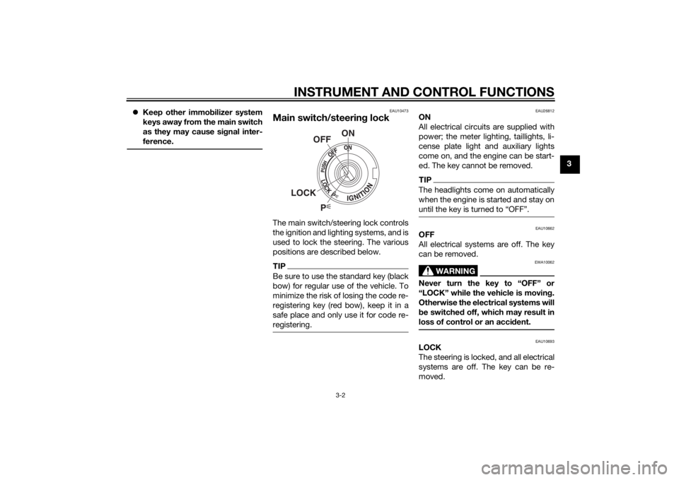
Main switch/steering lockThe main switch/steering lock controls
the ignition and lighting systems, and is
used to lock the steering. The various
positions are described below.TIPBe sure to use the standard key (black
bow) for regular use of the vehicle. To
minimize the risk of losing the code re-
registering key (red bow), keep it in a
safe place and only use it for code re-
registering.
EAU26812
ON
All electrical circuits are supplied with
power; the meter lighting, taillights, li-
cense plate light and auxiliary lights
come on, and the engine can be start-
ed. The key cannot be removed.TIPThe headlights come on automatically
when the engine is started and stay on
EAU10662
OFF
All electrical systems are off. The key
can be removed.
WARNING
EWA10062
Never turn the key to “OFF” or
“LOCK” while the vehicle is moving.
Otherwise the electrical systems will
be switched off, which may result in
loss of control or an accident.
EAU10693
LOCK
The steering is locked, and all electrical
systems are off. The key can be re-
moved.
P
ON
OFF
LOCK
U1MDE1E0.book Page 2 Monday, July 28, 2014 10:48 AM
Page 18 of 124

INSTRUMENT AND CONTROL FUNCTIONS
3-3
3To lock the steering
1. Turn the handlebars all the way to
the left or right.
2. Push the key in from the “OFF”
position, and then turn it to
“LOCK” while still pushing it.
3. Remove the key.To unlock the steering
Push the key into the main switch, and
then turn it to “OFF” while still pushing
it.
EAU39461
(Parking)
The steering is locked, and the tail-
lights, license plate light and auxiliary
lights are on. The hazard lights and turn
signal lights can be turned on, but all
other electrical systems are off. The
key can be removed.
The steering must be locked before the
key can be turned to “ ”.
NOTICE
ECA11021
Do not use the parking position for
an extended length of time, other-
wise the battery may discharge.
1. Push.
2. Turn.12
1. Push.
2. Turn.12
U1MDE1E0.book Page 3 Monday, July 28, 2014 10:48 AM
Page 19 of 124
INSTRUMENT AND CONTROL FUNCTIONS
3-4
3
EAU49396
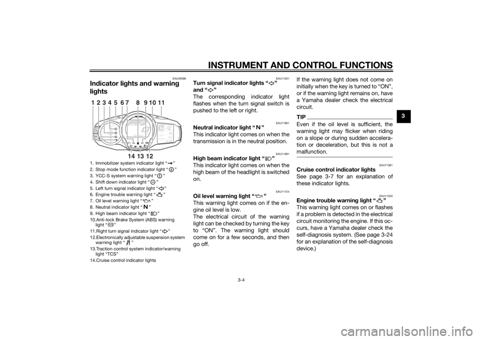
Indicator lights and warning
lights
EAU11031
Turn signal indicator lights “ ”
and“”
The corresponding indicator light
flashes when the turn signal switch is
pushed to the left or right.
EAU11061
Neutral indicator light “ ”
This indicator light comes on when the
transmission is in the neutral position.
EAU11081
High beam indicator light “ ”
This indicator light comes on when the
high beam of the headlight is switched
on.
EAU11124
Oil level warning light “ ”
This warning light comes on if the en-
gine oil level is low.
The electrical circuit of the warning
light can be checked by turning the key
to “ON”. The warning light should
come on for a few seconds, and then
go off.If the warning light does not come on
initially when the key is turned to “ON”,
or if the warning light remains on, have
a Yamaha dealer check the electrical
circuit.
TIPEven if the oil level is sufficient, the
warning light may flicker when riding
on a slope or during sudden accelera-
tion or deceleration, but this is not a
malfunction.
EAU11381
Cruise control indicator lights
See page 3-7 for an explanation of
these indicator lights.
EAU11535
Engine trouble warning light “ ”
This warning light comes on or flashes
if a problem is detected in the electrical
circuit monitoring the engine. If this oc-
curs, have a Yamaha dealer check the
self-diagnosis system. (See page 3-24
for an explanation of the self-diagnosis
device.)
1. Immobilizer system indicator light “ ”
2. Stop mode function indicator light “ ”
3. YCC-S system warning light “ ”
4. Shift down indicator light “ ”
5. Left turn signal indicator light “ ”
6. Engine trouble warning light “ ”
7. Oil level warning light “ ”
8. Neutral indicator light “ ”
9. High beam indicator light “ ”
10.Anti-lock Brake System (ABS) warning
light “ ”
11.Right turn signal indicator light “ ”
12.Electronically adjustable suspension system
warning light “ ”
13.Traction control system indicator/warning
light “TCS”
14.Cruise control indicator lights
GEARN
25
A.TEMP ˚C
Lo
C.TEMP ˚C
0:06
TIME TRIP
1234
5
11
6
10
7
13
12
14
9
8
ABS
U1MDE1E0.book Page 4 Monday, July 28, 2014 10:48 AM
Page 21 of 124
INSTRUMENT AND CONTROL FUNCTIONS
3-6
3 Try to reset the traction control system
and the lights by following the proce-
dures under “Resetting” on page 3-32.
EAU55392
Electronically adjustable suspen-
sion system warning light “ ”
This warning light comes on if a prob-
lem is detected in the electronically ad-
justable suspension system.
The electrical circuit of the warning
light can be checked by turning the key
to “ON”. The warning light should
come on for a few seconds, and then
go off.
If the warning light does not come on
initially when the key is turned to “ON”,
or if the warning light remains on, have
a Yamaha dealer check the electrical
circuit.
EAU55431
Shift down indicator light “ ”
This indicator light flashes when the
transmission gear is too high for the
vehicle speed.To avoid damaging the YCC-S clutch,
the shift down indicator light flashes
when it is necessary to downshift. If
this occurs, downshift until the indica-
tor light stops flashing.
EAU55442
YCC-S system warning light “ ”
If this warning light comes on while rid-
ing, the YCC-S system may not work
correctly. If this occurs:
It may be impossible to shift out of
the gear you are in.
The clutch may stay engaged, so
a shuddering sensation may be
felt as you come to a stop.
Stop the vehicle when it is safe to do
so, and park it away from traffic. Have
a Yamaha dealer check the YCC-S
system.TIPIn order to be able to move the vehicle
after it has stopped, if shifting is impos-
sible using the hand shift lever and shift
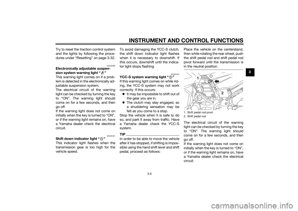
pedal, proceed as follows:Place the vehicle on the centerstand,
then while rotating the rear wheel, push
the shift pedal rod and shift pedal rod
pivot forward until the transmission is
in the neutral position.
The electrical circuit of the warning
light can be checked by turning the key
come on for a few seconds, and then
go off.
If the warning light does not come on
or if the warning light remains on, have
a Yamaha dealer check the electrical
circuit.1. Shift pedal rod pivot
2. Shift pedal rod
1
2
U1MDE1E0.book Page 6 Monday, July 28, 2014 10:48 AM
Page 41 of 124
INSTRUMENT AND CONTROL FUNCTIONS
3-26
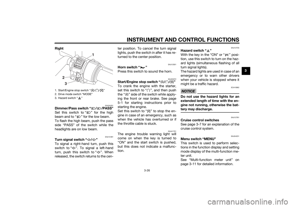
3 Right
EAU54201
Dimmer/Pass switch “ / /PASS”
Set this switch to “ ” for the high
beam and to “ ” for the low beam.
To flash the high beam, push the pass
side “PASS” of the switch while the
headlights are on low beam.
EAU12461
Turn signal switch “ / ”
To signal a right-hand turn, push this
switch to “ ”. To signal a left-hand
turn, push this switch to “ ”. When
released, the switch returns to the cen-ter position. To cancel the turn signal
lights, push the switch in after it has re-
turned to the center position.
EAU12501
Horn switch “ ”
Press this switch to sound the horn.
EAU55372
Start/Engine stop switch “ / / ”
To crank the engine with the starter,
set this switch to “ ”, and then push
the “ ” side of the switch while apply-
ing the front or rear brake. See page
5-1 for starting instructions prior to
starting the engine.
Set this switch to “ ” to stop the en-
gine in case of an emergency, such as
when the vehicle has overturned or if
the throttle cable is stuck.
EAU41701
The engine trouble warning light will
come on when the key is turned to
“ON” and the start switch is pushed,
but this does not indicate a malfunc-
tion.
EAU12735
Hazard switch “ ”
With the key in the “ON” or “ ” posi-
tion, use this switch to turn on the haz-
ard lights (simultaneous flashing of all
turn signal lights).
The hazard lights are used in case of an
emergency or to warn other drivers
when your vehicle is stopped where it
might be a traffic hazard.NOTICE
ECA10062
Do not use the hazard lights for an
extended length of time with the en-
gine not running, otherwise the bat-
tery may discharge.
EAU12781
Cruise control switches
See page 3-7 for an explanation of the
cruise control system.
EAU54231
Menu switch “MENU”
This switch is used to perform selec-
tions in the function display and setting
mode display of the multi-function me-
ter unit.
See “Multi-function meter unit” on
page 3-11 for detailed information.
1. Start/Engine stop switch “ / / ”
2. Drive mode switch “MODE”
3. Hazard switch “ ”
STOPM
O
D
ERUNSTART
32
1
U1MDE1E0.book Page 26 Monday, July 28, 2014 10:48 AM
Page 48 of 124
INSTRUMENT AND CONTROL FUNCTIONS
3-33
3
TIPThe fuel tank cap cannot be closed un-
less the key is in the lock. In addition,
the key cannot be removed if the cap is
not properly closed and locked.
WARNING
EWA11092
Make sure that the fuel tank cap is
properly closed after filling fuel.
Leaking fuel is a fire hazard.
EAU13222
FuelMake sure there is sufficient gasoline in
the tank.
WARNING
EWA10882
Gasoline and gasoline vapors are
extremely flammable. To avoid fires
and explosions and to reduce the
risk of injury when refueling, follow
these instructions.1. Before refueling, turn off the en-
gine and be sure that no one is sit-
ting on the vehicle. Never refuel
while smoking, or while in the vi-
cinity of sparks, open flames, or
other sources of ignition such as
the pilot lights of water heaters
and clothes dryers.
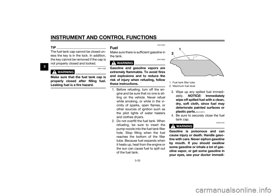
2. Do not overfill the fuel tank. When
refueling, be sure to insert the
pump nozzle into the fuel tank filler
hole. Stop filling when the fuel
reaches the bottom of the filler
tube. Because fuel expands when
it heats up, heat from the engine or
the sun can cause fuel to spill out
of the fuel tank.3. Wipe up any spilled fuel immedi-
ately. NOTICE: Immediately
wipe off spilled fuel with a clean,
dry, soft cloth, since fuel may
deteriorate painted surfaces or
plastic parts.
[ECA10072]
4. Be sure to securely close the fuel
tank cap.
WARNING
EWA15152
Gasoline is poisonous and can
cause injury or death. Handle gaso-
line with care. Never siphon gasoline
by mouth. If you should swallow
some gasoline or inhale a lot of gas-
oline vapor, or get some gasoline in
your eyes, see your doctor immedi-1. Fuel tank filler tube
2. Maximum fuel level
U1MDE1E0.book Page 33 Monday, July 28, 2014 10:48 AM
Page 55 of 124

INSTRUMENT AND CONTROL FUNCTIONS
3-40
3
EAU39612
Adjusting the headlight beamsThe headlight beam adjusting knobs
are used to raise or lower the height of
the headlight beams. It may be neces-
sary to adjust the headlight beams to
increase visibility and help prevent
blinding oncoming drivers when carry-
ing more or less load than usual. Obey
local laws and regulations when ad-
justing the headlights.
To raise the headlight beams, turn the
knobs in direction (a). To lower the
headlight beams, turn the knobs in di-
rection (b).
EAU39642
Handlebar positionThe handlebars can be adjusted to one
of three positions to suit the rider’s
preference. Have a Yamaha dealer ad-
just the position of the handlebars.
EAU54151
Opening and closing the cowl-
ing ventsThe cowling vents can be opened 20
mm (0.79 in) for added ventilation to
suit the riding conditions.
To open a cowling vent
1. Remove the quick fastener.
2. Slide the cowling vent panel for-
ward to unhook its projections
from the lower slots, and then pull
the panel off.
1. Headlight beam adjusting knob
1
1
(b)
(a)
(b)
(a)
1. Handlebar
11
1. Closed position
2. Open position
1
2
U1MDE1E0.book Page 40 Monday, July 28, 2014 10:48 AM