transmission YAMAHA FJR1300AS 2015 Owners Manual
[x] Cancel search | Manufacturer: YAMAHA, Model Year: 2015, Model line: FJR1300AS, Model: YAMAHA FJR1300AS 2015Pages: 124, PDF Size: 3.39 MB
Page 12 of 124

SAFETY INFORMATION
1-5
1operator and may limit control
ability, therefore, such accesso-
ries are not recommended.
Use caution when adding electri-
cal accessories. If electrical ac-
cessories exceed the capacity of
the motorcycle’s electrical sys-
tem, an electric failure could re-
sult, which could cause a
dangerous loss of lights or engine
power.
Aftermarket Tires and Rims
The tires and rims that came with your
motorcycle were designed to match
the performance capabilities and to
provide the best combination of han-
dling, braking, and comfort. Other
tires, rims, sizes, and combinations
may not be appropriate. Refer to page
6-18 for tire specifications and more in-
formation on replacing your tires.
Transporting the Motorcycle
Be sure to observe following instruc-
tions before transporting the motorcy-
cle in another vehicle.
Remove all loose items from the
motorcycle.Check that the fuel cock (if
equipped) is in the “OFF” position
and that there are no fuel leaks.
Point the front wheel straight
ahead on the trailer or in the truck
bed, and choke it in a rail to pre-
vent movement.
Shift the transmission in gear (for
models with a manual transmis-
sion).
Secure the motorcycle with tie-
downs or suitable straps that are
attached to solid parts of the mo-
torcycle, such as the frame or up-
per front fork triple clamp (and not,
for example, to rubber-mounted
handlebars or turn signals, or
parts that could break). Choose
the location for the straps carefully
so the straps will not rub against
painted surfaces during transport.
The suspension should be com-
pressed somewhat by the tie-
downs, if possible, so that the mo-
torcycle will not bounce exces-
sively during transport.
U1MDE1E0.book Page 5 Monday, July 28, 2014 10:48 AM
Page 19 of 124
INSTRUMENT AND CONTROL FUNCTIONS
3-4
3
EAU49396
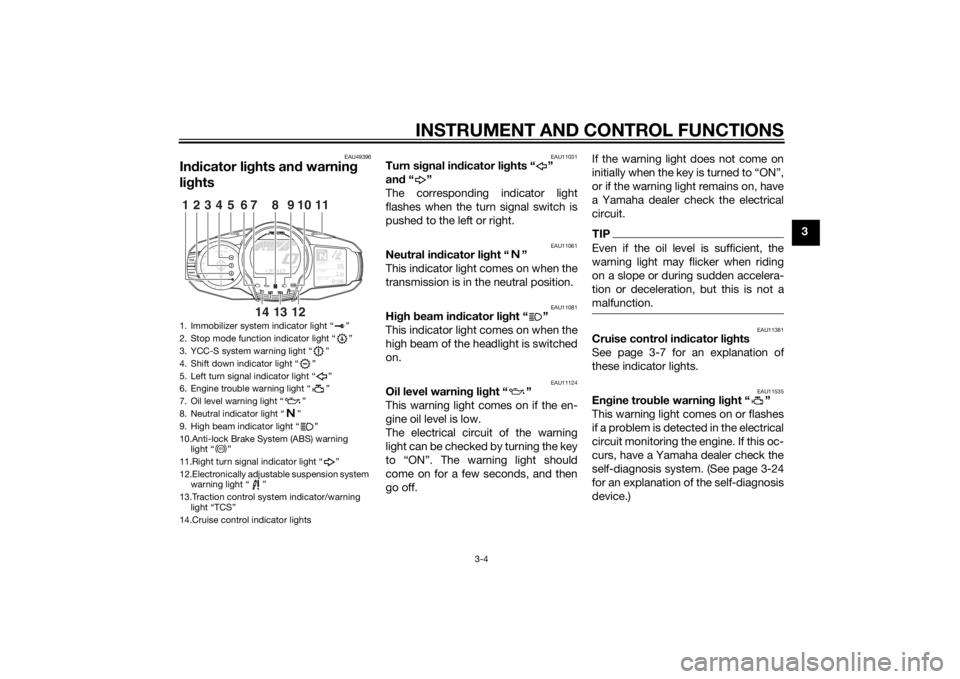
Indicator lights and warning
lights
EAU11031
Turn signal indicator lights “ ”
and“”
The corresponding indicator light
flashes when the turn signal switch is
pushed to the left or right.
EAU11061
Neutral indicator light “ ”
This indicator light comes on when the
transmission is in the neutral position.
EAU11081
High beam indicator light “ ”
This indicator light comes on when the
high beam of the headlight is switched
on.
EAU11124
Oil level warning light “ ”
This warning light comes on if the en-
gine oil level is low.
The electrical circuit of the warning
light can be checked by turning the key
to “ON”. The warning light should
come on for a few seconds, and then
go off.If the warning light does not come on
initially when the key is turned to “ON”,
or if the warning light remains on, have
a Yamaha dealer check the electrical
circuit.
TIPEven if the oil level is sufficient, the
warning light may flicker when riding
on a slope or during sudden accelera-
tion or deceleration, but this is not a
malfunction.
EAU11381
Cruise control indicator lights
See page 3-7 for an explanation of
these indicator lights.
EAU11535
Engine trouble warning light “ ”
This warning light comes on or flashes
if a problem is detected in the electrical
circuit monitoring the engine. If this oc-
curs, have a Yamaha dealer check the
self-diagnosis system. (See page 3-24
for an explanation of the self-diagnosis
device.)
1. Immobilizer system indicator light “ ”
2. Stop mode function indicator light “ ”
3. YCC-S system warning light “ ”
4. Shift down indicator light “ ”
5. Left turn signal indicator light “ ”
6. Engine trouble warning light “ ”
7. Oil level warning light “ ”
8. Neutral indicator light “ ”
9. High beam indicator light “ ”
10.Anti-lock Brake System (ABS) warning
light “ ”
11.Right turn signal indicator light “ ”
12.Electronically adjustable suspension system
warning light “ ”
13.Traction control system indicator/warning
light “TCS”
14.Cruise control indicator lights
GEARN
25
A.TEMP ˚C
Lo
C.TEMP ˚C
0:06
TIME TRIP
1234
5
11
6
10
7
13
12
14
9
8
ABS
U1MDE1E0.book Page 4 Monday, July 28, 2014 10:48 AM
Page 21 of 124
INSTRUMENT AND CONTROL FUNCTIONS
3-6
3 Try to reset the traction control system
and the lights by following the proce-
dures under “Resetting” on page 3-32.
EAU55392
Electronically adjustable suspen-
sion system warning light “ ”
This warning light comes on if a prob-
lem is detected in the electronically ad-
justable suspension system.
The electrical circuit of the warning
light can be checked by turning the key
to “ON”. The warning light should
come on for a few seconds, and then
go off.
If the warning light does not come on
initially when the key is turned to “ON”,
or if the warning light remains on, have
a Yamaha dealer check the electrical
circuit.
EAU55431
Shift down indicator light “ ”
This indicator light flashes when the
transmission gear is too high for the
vehicle speed.To avoid damaging the YCC-S clutch,
the shift down indicator light flashes
when it is necessary to downshift. If
this occurs, downshift until the indica-
tor light stops flashing.
EAU55442
YCC-S system warning light “ ”
If this warning light comes on while rid-
ing, the YCC-S system may not work
correctly. If this occurs:
It may be impossible to shift out of
the gear you are in.
The clutch may stay engaged, so
a shuddering sensation may be
felt as you come to a stop.
Stop the vehicle when it is safe to do
so, and park it away from traffic. Have
a Yamaha dealer check the YCC-S
system.TIPIn order to be able to move the vehicle
after it has stopped, if shifting is impos-
sible using the hand shift lever and shift
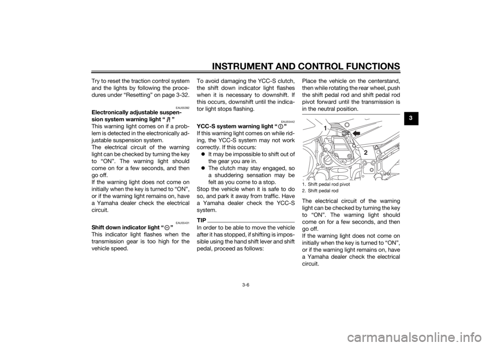
pedal, proceed as follows:Place the vehicle on the centerstand,
then while rotating the rear wheel, push
the shift pedal rod and shift pedal rod
pivot forward until the transmission is
in the neutral position.
The electrical circuit of the warning
light can be checked by turning the key
come on for a few seconds, and then
go off.
If the warning light does not come on
or if the warning light remains on, have
a Yamaha dealer check the electrical
circuit.1. Shift pedal rod pivot
2. Shift pedal rod
1
2
U1MDE1E0.book Page 6 Monday, July 28, 2014 10:48 AM
Page 26 of 124
INSTRUMENT AND CONTROL FUNCTIONS
3-11
3tem warning light is on, or while the
cruise control system is malfunction-
ing.
WARNING
EWA16361
If the cruise control system is not
working correctly, the “ ” indicator
light will flash. If this occurs, turn the
cruise control system off and have a
Yamaha dealer check it.NOTICE
ECA11591
If the display indicates an error
code, the vehicle should be checked
as soon as possible in order to avoid
engine damage.
EAU55413
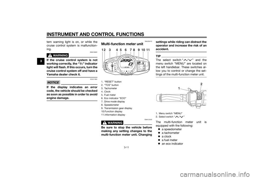
Multi-function meter unit
WARNING
EWA12423
Be sure to stop the vehicle before
making any setting changes to the
multi-function meter unit. Changingsettings while riding can distract the
operator and increase the risk of an
accident.
TIPThe select switch “ / ” and the
menu switch “MENU” are located on
the left handlebar. These switches al-
low you to control or change the set-
tings of the multi-function meter unit.The multi-function meter unit is
equipped with the following:
a speedometer
a tachometer
a clock
a fuel meter
an eco indicator
1. “RESET” button
2. “TCS” button
3. Tachometer
4. Clock
5. Fuel meter
6. Eco indicator “ECO”
7. Drive mode display
8. Speedometer
9. Transmission gear display
10.Function display
11.Information display
GEARN
25
A.TEMP ˚C
Lo
C.TEMP ˚C
0:06
TIME TRIP
12
3
11
4
5
8
7
6
9
10
1. Menu switch “MENU”
2. Select switch “ / ”
1
2
U1MDE1E0.book Page 11 Monday, July 28, 2014 10:48 AM
Page 27 of 124
INSTRUMENT AND CONTROL FUNCTIONS
3-12
3 a transmission gear display
a drive mode display (which
shows the selected drive mode)
a function display (which shows
the selected function)
an information display (which
shows various information, such
as the odometer reading)
a setting mode display (which al-
lows you to set, select, or reset the
items shown in the information
display)
a self-diagnosis device
TIPBe sure to turn the key to “ON” be-
fore pushing the select
switch “ / ”, menu switch
“MENU”, “RESET” button and
“TCS” button.
For the UK only: To switch the me-
ter displays between kilometers
and miles, see page 3-18.Speedometer
The speedometer shows the vehicle’s
traveling speed.Tachometer
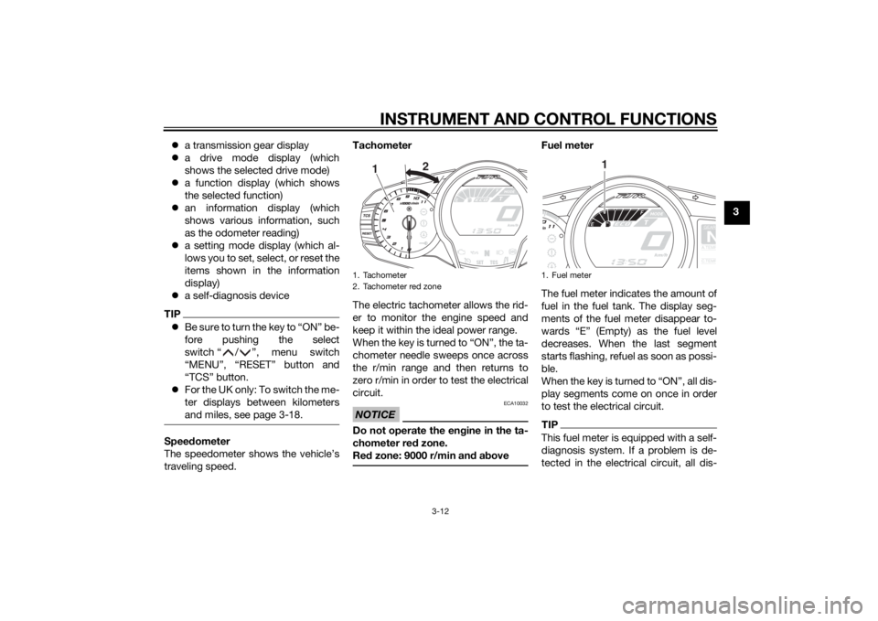
The electric tachometer allows the rid-
er to monitor the engine speed and
keep it within the ideal power range.
When the key is turned to “ON”, the ta-
chometer needle sweeps once across
the r/min range and then returns to
zero r/min in order to test the electrical
circuit.
NOTICE
ECA10032
Do not operate the engine in the ta-
chometer red zone.
Red zone: 9000 r/min and above
Fuel meter
The fuel meter indicates the amount of
fuel in the fuel tank. The display seg-
ments of the fuel meter disappear to-
wards “E” (Empty) as the fuel level
decreases. When the last segment
starts flashing, refuel as soon as possi-
ble.
When the key is turned to “ON”, all dis-
play segments come on once in order
to test the electrical circuit.TIPThis fuel meter is equipped with a self-
diagnosis system. If a problem is de-
tected in the electrical circuit, all dis-
1. Tachometer
2. Tachometer red zone
12
1. Fuel meter
GEARNA.TEM
P
C.TEM
P
1
U1MDE1E0.book Page 12 Monday, July 28, 2014 10:48 AM
Page 28 of 124
INSTRUMENT AND CONTROL FUNCTIONS
3-13
3play segments start flashing. If this
occurs, have a Yamaha dealer check
the electrical circuit.
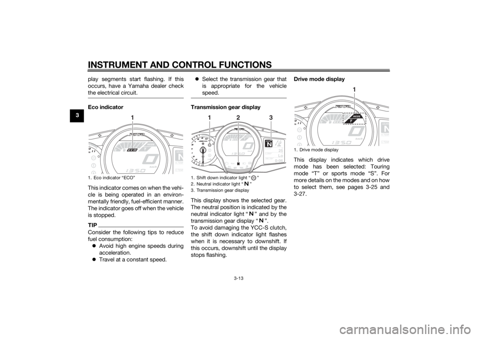
Eco indicator
This indicator comes on when the vehi-
cle is being operated in an environ-
mentally friendly, fuel-efficient manner.
The indicator goes off when the vehicle
is stopped.TIPConsider the following tips to reduce
fuel consumption:
Avoid high engine speeds during
acceleration.
Travel at a constant speed.Select the transmission gear that
is appropriate for the vehicle
speed.
Transmission gear display
This display shows the selected gear.
The neutral position is indicated by the
neutral indicator light “ ” and by the
transmission gear display “ ”.
To avoid damaging the YCC-S clutch,
the shift down indicator light flashes
when it is necessary to downshift. If
this occurs, downshift until the display
stops flashing.Drive mode display
This display indicates which drive
mode has been selected: Touring
mode “T” or sports mode “S”. For
more details on the modes and on how
to select them, see pages 3-25 and
3-27.
1. Eco indicator “ECO”
GEARNA.TEM
P
C.TEM
P
1
1. Shift down indicator light “ ”
2. Neutral indicator light “ ”
3. Transmission gear display
GEARN
25
A.TEMP ˚C
Lo
C.TEMP ˚C
0:06
TIME TRIP
2
1
3
1. Drive mode display
GEARNA.TEM
P
C.TEM
P
1
U1MDE1E0.book Page 13 Monday, July 28, 2014 10:48 AM
Page 33 of 124
INSTRUMENT AND CONTROL FUNCTIONS
3-18
3 The “L/100km” display shows the
amount of fuel necessary to travel
100 km.
For the UK only: The “MPG” dis-
play shows the distance that can
be traveled on 1.0 Imp.gal of fuel.
TIPIf traveling at speeds under 10 km/h (6
NOTICE
ECA15474
If there is a malfunction, “– –.–” will
be continuously displayed. Have a
Yamaha dealer check the vehicle.Adjusting the windshield positionTo move the windshield up, push
the “ ” side of the select switch. To
move the windshield down, push
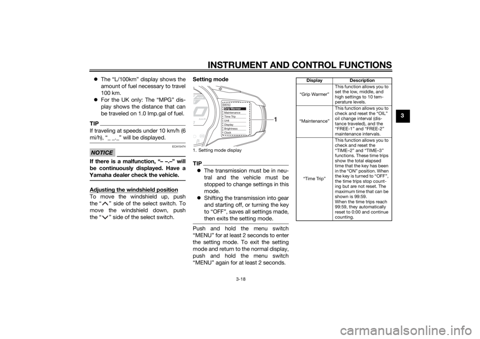
the “ ” side of the select switch.Setting mode
TIPThe transmission must be in neu-
tral and the vehicle must be
stopped to change settings in this
mode.
Shifting the transmission into gear
and starting off, or turning the key
to “OFF”, saves all settings made,
then exits the setting mode.Push and hold the menu switch
“MENU” for at least 2 seconds to enter
the setting mode. To exit the setting
mode and return to the normal display,
push and hold the menu switch
“MENU” again for at least 2 seconds.1. Setting mode display
MENUGrip WarmerMaintenanceTime TripUnitDisplayBrightnessClock
1
Display Description
“Grip Warmer”This function allows you to
set the low, middle, and
high settings to 10 tem-
perature levels.
“Maintenance”This function allows you to
check and reset the “OIL”
oil change interval (dis-
tance traveled), and the
“FREE-1” and “FREE-2”
maintenance intervals.
“Time Trip”This function allows you to
check and reset the
“TIME–2” and “TIME–3”
functions. These time trips
show the total elapsed
time that the key has been
in the “ON” position. When
the key is turned to “OFF”,
the time trips stop count-
ing but are not reset. The
maximum time that can be
shown is 99:59.
When the time trips reach
99:59, they automatically
reset to 0:00 and continue
counting.
U1MDE1E0.book Page 18 Monday, July 28, 2014 10:48 AM
Page 42 of 124
INSTRUMENT AND CONTROL FUNCTIONS
3-27
3
EAU54221
Select switch “ / ”
This switch is used to perform selec-
tions in the function display and setting
mode display of the multi-function me-
ter unit.
See “Multi-function meter unit” on
page 3-11 for detailed information.
EAU55463
Stop mode function switch “ ”
When this switch is pushed, the stop
mode function is activated and the
stop mode function indicator light
comes on.
When the stop mode function is acti-
vated, the function works together with
the YCC-S system to automatically
shift down to 1st gear according to the
vehicle speed.
If this function is activated and the
transmission is in 2nd gear or higher
when the rider stops the vehicle, the
function will automatically shift down
to 1st gear.
TIPWhen the stop mode function is acti-
vated, the shift down indicator light will
flash only when the rider attempts to
start off in 2nd gear or higher.
EAU54691
Drive mode switch “MODE”
WARNING
EWA15341
Do not change the D-mode while the
vehicle is moving.Using this switch changes the drive
mode to touring mode “T” or sports
mode “S”.
The throttle grip must be completely
closed in order to change the drive
mode.
The selected mode is shown on the
drive mode display. (See page 3-13.)
The drive mode cannot be changed
while the cruise control system is oper-
ating.
EAU55491
YCC-S systemThis vehicle features the YCC-S
(Yamaha Chip Controlled-Shift) sys-
tem.
The basic function of this system al-
lows the rider to shift gears without the
use of a clutch lever. Furthermore, a
hand shift lever is equipped on the
handlebar, allowing the rider to shift
gears with either the foot-operated
shift pedal or the hand-operated shift
lever. (See page 3-29.)
When the engine is started and the
shift pedal or the shift lever is moved, a
signal is sent to the MCU (Motor Con-
trol Unit) which disengages the clutch,
the ECU (Engine Control Unit) then ad-
justs the electronic throttle valve, the
gear shift is made and then the clutch
is re-engaged once the engine is run-
ning at the proper speed. Clutch en-
gagement is controlled optimally by
the MCU according to engine r/min,
engine requirements, and riding condi-
tions.
U1MDE1E0.book Page 27 Monday, July 28, 2014 10:48 AM
Page 43 of 124
INSTRUMENT AND CONTROL FUNCTIONS
3-28
3
TIPThis is not an automatic transmission,
only the clutch system is automatic.
The gears must be shifted by the rider
except when stopping the vehicle
while the stop mode function is activat-
ed.See “Stop mode function switch” (See
page 3-27.) and OPERATION AND IM-
PORTANT RIDING POINTS (See page
5-1.) for further explanation of this sys-
tem.
EAU40496
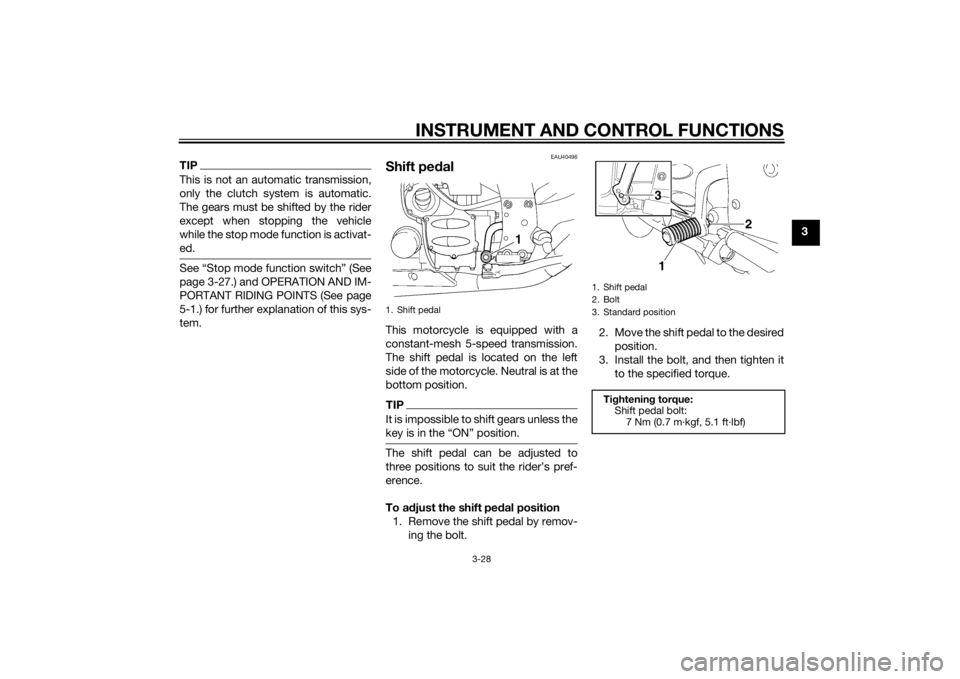
Shift pedalThis motorcycle is equipped with a
constant-mesh 5-speed transmission.
The shift pedal is located on the left
side of the motorcycle. Neutral is at the
bottom position.TIPIt is impossible to shift gears unless the
The shift pedal can be adjusted to
erence.
To adjust the shift pedal position
1. Remove the shift pedal by remov-
ing the bolt.2. Move the shift pedal to the desired
position.
3. Install the bolt, and then tighten it
to the specified torque.1. Shift pedal
1. Shift pedal
2. Bolt
3. Standard position
Tightening torque:
Shift pedal bolt:
7 Nm (0.7 m·kgf, 5.1 ft·lbf)
31
2
U1MDE1E0.book Page 28 Monday, July 28, 2014 10:48 AM
Page 63 of 124
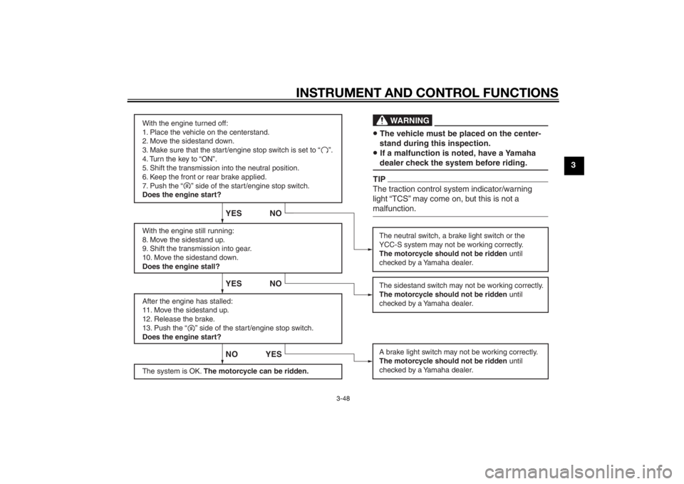
INSTRUMENT AND CONTROL FUNCTIONS
3-48
3
With the engine turned off:
1. Place the vehicle on the centerstand.
2. Move the sidestand down.
3. Make sure that the start/engine stop switch is set to “ ”.
4. Turn the key to “ON”.
5. Shift the transmission into the neutral position.
6. Keep the front or rear brake applied.
7. Push the “ ” side of the start/engine stop switch.
Does the engine start?
With the engine still running:
8. Move the sidestand up.
9. Shift the transmission into gear.
10. Move the sidestand down.
Does the engine stall?
After the engine has stalled:
11. Move the sidestand up.
12. Release the brake.
13. Push the “ ” side of the start/engine stop switch.
Does the engine start?
The system is OK. The motorcycle can be ridden.
NO
YES YES NO YES
NO
The neutral switch, a brake light switch or the
YCC-S system may not be working correctly.
The motorcycle should not be ridden until
checked by a Yamaha dealer.
A brake light switch may not be working correctly.
The motorcycle should not be ridden until
checked by a Yamaha dealer.The sidestand switch may not be working correctly.
The motorcycle should not be ridden until
checked by a Yamaha dealer.• The vehicle must be placed on the center-
stand during this inspection.• If a malfunction is noted, have a Yamaha
dealer check the system before riding.
WA R N I N G
TIPThe traction control system indicator/warning
light “TCS” may come on, but this is not a
malfunction.
U1MDE1E0.book Page 48 Monday, July 28, 2014 10:48 AM