clock YAMAHA FJR1300AS 2020 Owners Manual
[x] Cancel search | Manufacturer: YAMAHA, Model Year: 2020, Model line: FJR1300AS, Model: YAMAHA FJR1300AS 2020Pages: 122, PDF Size: 3.42 MB
Page 23 of 122
Instrument and control functions
3-9
3
When traveling with a set cruising
speed, if the cruise control system is
deactivated under the above condi-
tions, the ŌĆ£ ŌĆØ indicator light will go off
and the ŌĆ£SETŌĆØ indicator light will flash
for 4 seconds, and then go off.
When not traveling with a set cruising
speed, if the start/engine stop switch is
set to the ŌĆ£ ŌĆØ position, the engine
stalls, or the sidestand is lowered, then
the ŌĆ£ ŌĆØ indicator light will go off (the
ŌĆ£SETŌĆØ indicator light will not flash).
If the cruise control system is automat-
ically deactivated, please stop and
confirm that your vehicle is in good op-
erating condition.
Before using the cruise control system
again, activate it using the power
switch.
TIP
In some cases, the cruise control sys-
tem may not be able to maintain the set
cruising speed when the vehicle is
traveling uphill or downhill.
’ü¼ When the vehicle is traveling up-
hill, the actual traveling speed may
become lower than the set cruis-
ing speed. If this occurs, acceler-
ate to the desired traveling speed
using the throttle.
’ü¼ When the vehicle is traveling
downhill, the actual traveling
speed may become higher than
the set cruising speed. If this oc-
curs, the setting switch cannot be
used to adjust the set cruising
speed. To reduce the traveling
speed, apply the brakes. When
the brakes are applied, the cruise
control system will become deac-
tivated.
EAU55418
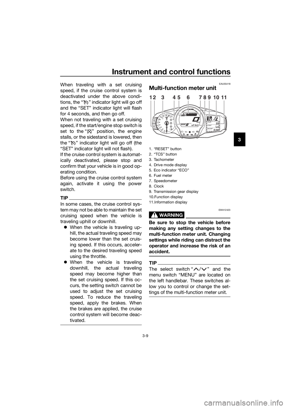
Multi-function meter unit
WARNING
EWA12423
Be sure to stop the vehicle before
makin g any settin g chan ges to the
multi-function meter unit. Chang ing
settin gs while ri din g can d istract the
operator an d increase the risk of an
acci dent.
TIP
The select switch ŌĆ£ / ŌĆØ and the
menu switch ŌĆ£MENUŌĆØ are located on
the left handlebar. These switches al-
low you to control or change the set-
tings of the multi-function meter unit.
1. ŌĆ£RESETŌĆØ button
2. ŌĆ£TCSŌĆØ button
3. Tachometer
4. Drive mode display
5. Eco indicator ŌĆ£ECOŌĆØ
6. Fuel meter
7. Speedometer
8. Clock
9. Transmission gear display
10.Function display
11.Information display
GEARN25A.TEMP ˚C
LoC.TEMP˚C
0:06TIME TRIP
1231145786910
UB95E2E0.book Page 9 Tuesday, December 17, 2019 10:29 AM
Page 24 of 122
Instrument and control functions
3-10
3
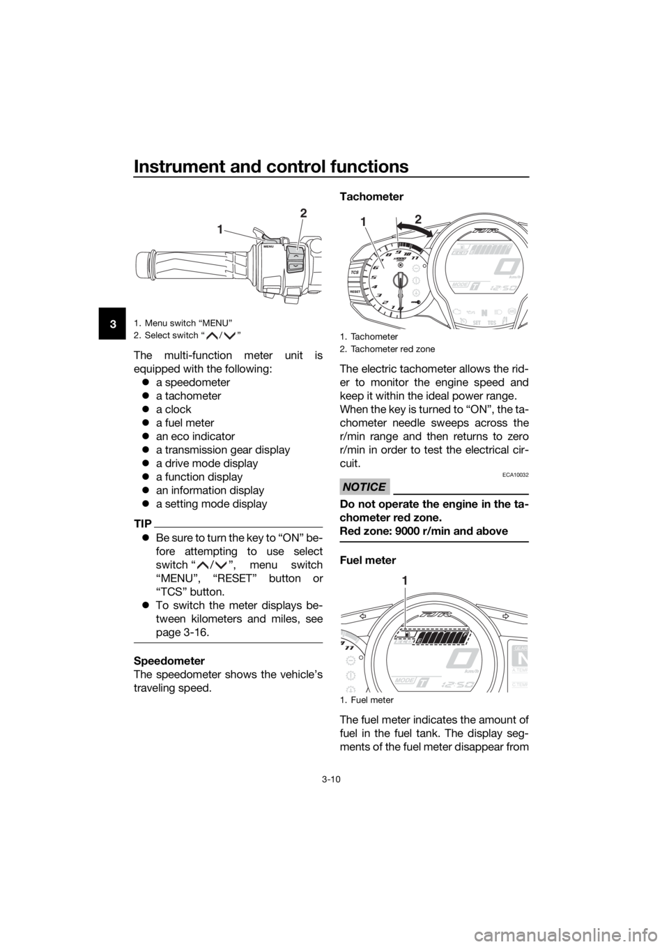
The multi-function meter unit is
equipped with the following:’ü¼ a speedometer
’ü¼ a tachometer
’ü¼ a clock
’ü¼ a fuel meter
’ü¼ an eco indicator
’ü¼ a transmission gear display
’ü¼ a drive mode display
’ü¼ a function display
’ü¼ an information display
’ü¼ a setting mode display
TIP
’ü¼Be sure to turn the key to ŌĆ£ONŌĆØ be-
fore attempting to use select
switch ŌĆ£ / ŌĆØ, menu switch
ŌĆ£MENUŌĆØ, ŌĆ£RESETŌĆØ button or
ŌĆ£TCSŌĆØ button.
’ü¼ To switch the meter displays be-
tween kilometers and miles, see
page 3-16.
Speed ometer
The speedometer shows the vehicleŌĆÖs
traveling speed. Tachometer
The electric tachometer allows the rid-
er to monitor the engine speed and
keep it within the ideal power range.
When the key is turned to ŌĆ£ONŌĆØ, the ta-
chometer needle sweeps across the
r/min range and then returns to zero
r/min in order to test the electrical cir-
cuit.
NOTICE
ECA10032
Do not operate the en
gine in the ta-
chometer red zone.
Re d zone: 9000 r/min an d a bove
Fuel meter
The fuel meter indicates the amount of
fuel in the fuel tank. The display seg-
ments of the fuel meter disappear from
1. Menu switch ŌĆ£MENUŌĆØ
2. Select switch ŌĆ£ / ŌĆØ
1
2
1. Tachometer
2. Tachometer red zone
1. Fuel meter
1 2
GEAR
NA.TEMP
C.TEMP
1
UB95E2E0.book Page 10 Tuesday, December 17, 2019 10:29 AM
Page 30 of 122
Instrument and control functions
3-16
3
NOTICE
ECA15474
If there is a malfunction, ŌĆ£ŌĆō ŌĆō.ŌĆōŌĆØ will
b e continuously displaye d. Have a
Yamaha dealer check the vehicle.
Adjusting the windshield position
To move the windshield up, push
the ŌĆ£ ŌĆØ side of the select switch. To
move the windshield down, push
the ŌĆ£ ŌĆØ side of the select switch.
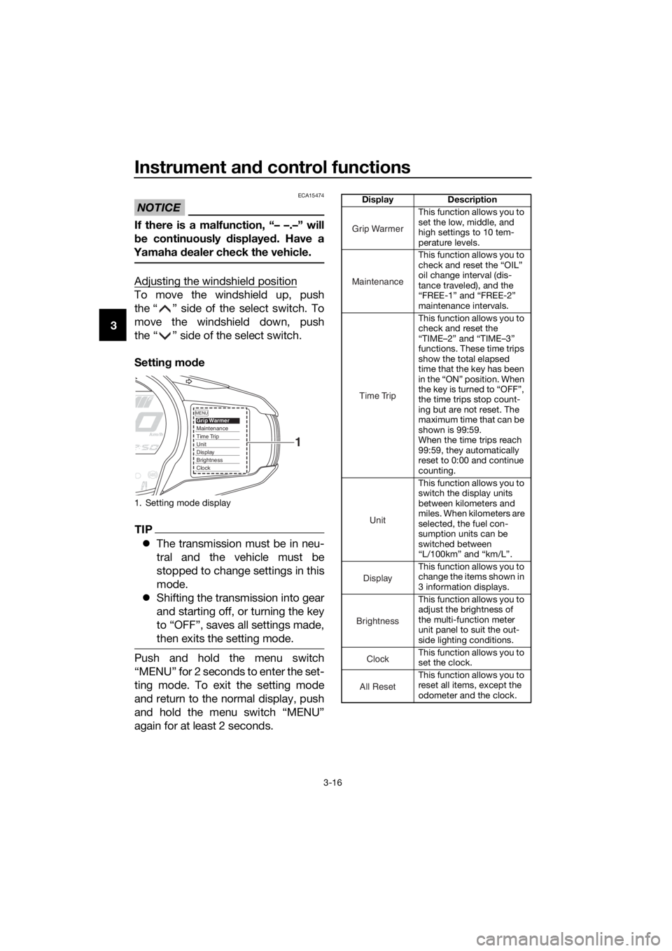
Settin g mo de
TIP
’ü¼ The transmission must be in neu-
tral and the vehicle must be
stopped to change settings in this
mode.
’ü¼ Shifting the transmission into gear
and starting off, or turning the key
to ŌĆ£OFFŌĆØ, saves all settings made,
then exits the setting mode.
Push and hold the menu switch
ŌĆ£MENUŌĆØ for 2 seconds to enter the set-
ting mode. To exit the setting mode
and return to the normal display, push
and hold the menu switch ŌĆ£MENUŌĆØ
again for at least 2 seconds.
1. Setting mode display
MENUGrip WarmerMaintenanceTime TripUnitDisplayBrightnessClock
1
Display Description
This function allows you to
set the low, middle, and
high settings to 10 tem-
perature levels.
This function allows you to
check and reset the ŌĆ£OILŌĆØ
oil change interval (dis-
tance traveled), and the
ŌĆ£FREE-1ŌĆØ and ŌĆ£FREE-2ŌĆØ
maintenance intervals.
This function allows you to
check and reset the
ŌĆ£TIMEŌĆō2ŌĆØ and ŌĆ£TIMEŌĆō3ŌĆØ
functions. These time trips
show the total elapsed
time that the key has been
in the ŌĆ£ONŌĆØ position. When
the key is turned to ŌĆ£OFFŌĆØ,
the time trips stop count-
ing but are not reset. The
maximum time that can be
shown is 99:59.
When the time trips reach
99:59, they automatically
reset to 0:00 and continue
counting.
This function allows you to
switch the display units
between kilometers and
miles. When kilometers are
selected, the fuel con-
sumption units can be
switched between
ŌĆ£L/100kmŌĆØ and ŌĆ£km/LŌĆØ.
This function allows you to
change the items shown in
3 information displays.
This function allows you to
adjust the brightness of
the multi-function meter
unit panel to suit the out-
side lighting conditions.
This function allows you to
set the clock.
This function allows you to
reset all items, except the
odometer and the clock.
Grip Warmer
Maintenance
Time Trip
Unit
Display
Brightness
Clock
All Reset
UB95E2E0.book Page 16 Tuesday, December 17, 2019 10:29 AM
Page 31 of 122
Instrument and control functions
3-17
3
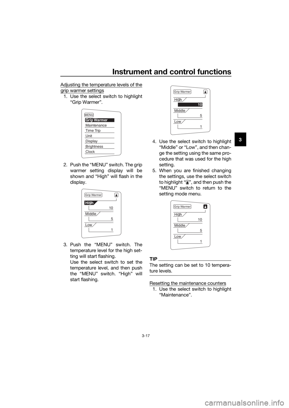
Adjusting the temperature levels of the
grip warmer settings
1. Use the select switch to highlight
ŌĆ£Grip WarmerŌĆØ.
2. Push the ŌĆ£MENUŌĆØ switch. The grip warmer setting display will be
shown and ŌĆ£HighŌĆØ will flash in the
display.
3. Push the ŌĆ£MENUŌĆØ switch. The temperature level for the high set-
ting will start flashing.
Use the select switch to set the
temperature level, and then push
the ŌĆ£MENUŌĆØ switch. ŌĆ£HighŌĆØ will
start flashing. 4. Use the select switch to highlight
ŌĆ£MiddleŌĆØ or ŌĆ£LowŌĆØ, and then chan-
ge the setting using the same pro-
cedure that was used for the high
setting.
5. When you are finished changing the settings, use the select switch
to highlight ŌĆ£ ŌĆØ, and then push the
ŌĆ£MENUŌĆØ switch to return to the
setting mode menu.
TIP
The setting can be set to 10 tempera-
ture levels.
Resetting the maintenance counters
1. Use the select switch to highlightŌĆ£MaintenanceŌĆØ.
MENU
Grip Warmer
Maintenance
Time Trip
Unit
Display
Brightness
Clock
Grip Warmer
Hig
h
10
Middle
5
Low
1
Grip Warmer
Hi g
h
10
Middle
5
Low
1
Grip Warmer
Hi g
h
10
Middle
5
Low
1
UB95E2E0.book Page 17 Tuesday, December 17, 2019 10:29 AM
Page 32 of 122
Instrument and control functions
3-18
3
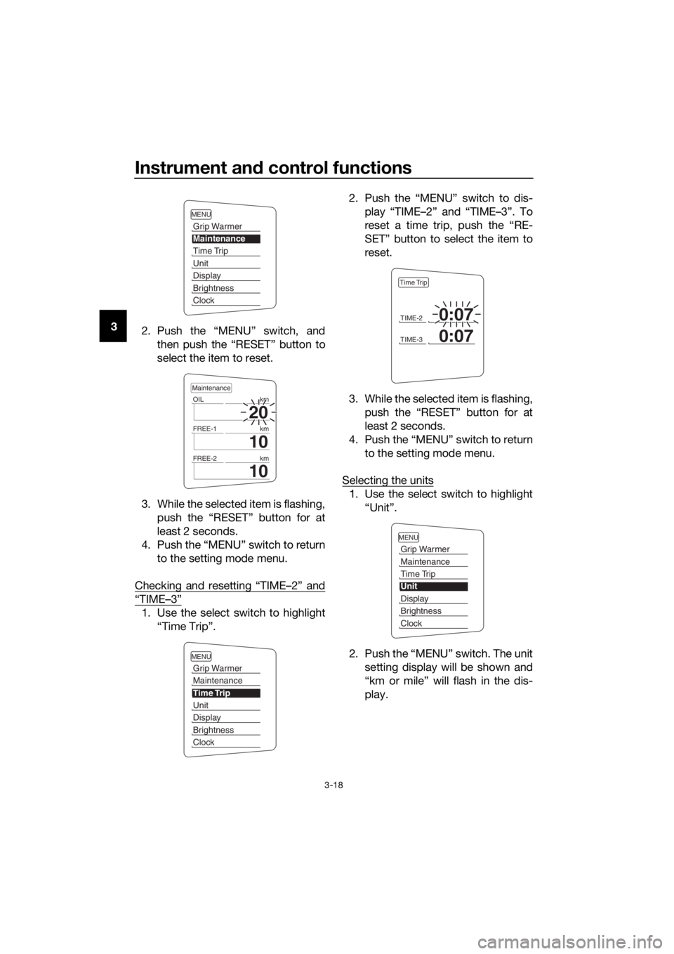
2. Push the ŌĆ£MENUŌĆØ switch, and
then push the ŌĆ£RESETŌĆØ button to
select the item to reset.
3. While the selected item is flashing, push the ŌĆ£RESETŌĆØ button for at
least 2 seconds.
4. Push the ŌĆ£MENUŌĆØ switch to return to the setting mode menu.
Checking and resetting ŌĆ£TIMEŌĆō2ŌĆØ and
ŌĆ£TIMEŌĆō3ŌĆØ
1. Use the select switch to highlight ŌĆ£Time TripŌĆØ. 2. Push the ŌĆ£MENUŌĆØ switch to dis-
play ŌĆ£TIMEŌĆō2ŌĆØ and ŌĆ£TIMEŌĆō3ŌĆØ. To
reset a time trip, push the ŌĆ£RE-
SETŌĆØ button to select the item to
reset.
3. While the selected item is flashing, push the ŌĆ£RESETŌĆØ button for at
least 2 seconds.
4. Push the ŌĆ£MENUŌĆØ switch to return to the setting mode menu.
Selecting the units
1. Use the select switch to highlight ŌĆ£UnitŌĆØ.
2. Push the ŌĆ£MENUŌĆØ switch. The unit setting display will be shown and
ŌĆ£km or mileŌĆØ will flash in the dis-
play.
MENU
Grip Warmer
Maintenance
Time Trip
Unit
Display
Brightness
Clock
20
OIL km
10
FREE-1km
10
FREE-2km
Maintenance
MENU
Grip Warmer
Maintenance
Time Trip
Unit
Display
Brightness
Clock
TIME-20:07
TIME-30:07
Time Trip
MENU
Grip Warmer
Maintenance
Time Trip
Unit
Display
Brightness
Clock
UB95E2E0.book Page 18 Tuesday, December 17, 2019 10:29 AM
Page 33 of 122
Instrument and control functions
3-19
3
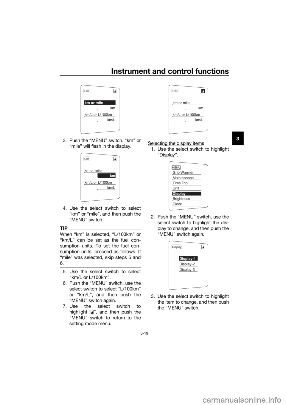
3. Push the ŌĆ£MENUŌĆØ switch. ŌĆ£kmŌĆØ or
ŌĆ£mileŌĆØ will flash in the display.
4. Use the select switch to select ŌĆ£kmŌĆØ or ŌĆ£mileŌĆØ, and then push the
ŌĆ£MENUŌĆØ switch.
TIP
When ŌĆ£kmŌĆØ is selected, ŌĆ£L/100kmŌĆØ or
ŌĆ£km/LŌĆØ can be set as the fuel con-
sumption units. To set the fuel con-
sumption units, proceed as follows. If
ŌĆ£mileŌĆØ was selected, skip steps 5 and
6.
5. Use the select switch to selectŌĆ£km/L or L/100kmŌĆØ.
6. Push the ŌĆ£MENUŌĆØ switch, use the select switch to select ŌĆ£L/100kmŌĆØ
or ŌĆ£km/LŌĆØ, and then push the
ŌĆ£MENUŌĆØ switch again.
7. Use the select switch to highlight ŌĆ£ ŌĆØ, and then push the
ŌĆ£MENUŌĆØ switch to return to the
setting mode menu. Selecting the display items
1. Use the select switch to highlight
ŌĆ£DisplayŌĆØ.
2. Push the ŌĆ£MENUŌĆØ switch, use the select switch to highlight the dis-
play to change, and then push the
ŌĆ£MENUŌĆØ switch again.
3. Use the select switch to highlight the item to change, and then push
the ŌĆ£MENUŌĆØ switch.
Unit
km or mile
km
km/L or L/100km
km/L
Unit
km or mile
km
km/L or L/100km
km/L
Unit
km or mile
km
km/L or L/100km
km/L
MENU
Grip Warmer
Maintenance
Time Trip
Unit
Display
Brightness
Clock
Display
Display-1
Display-2
Display-3
UB95E2E0.book Page 19 Tuesday, December 17, 2019 10:29 AM
Page 34 of 122
Instrument and control functions
3-20
3
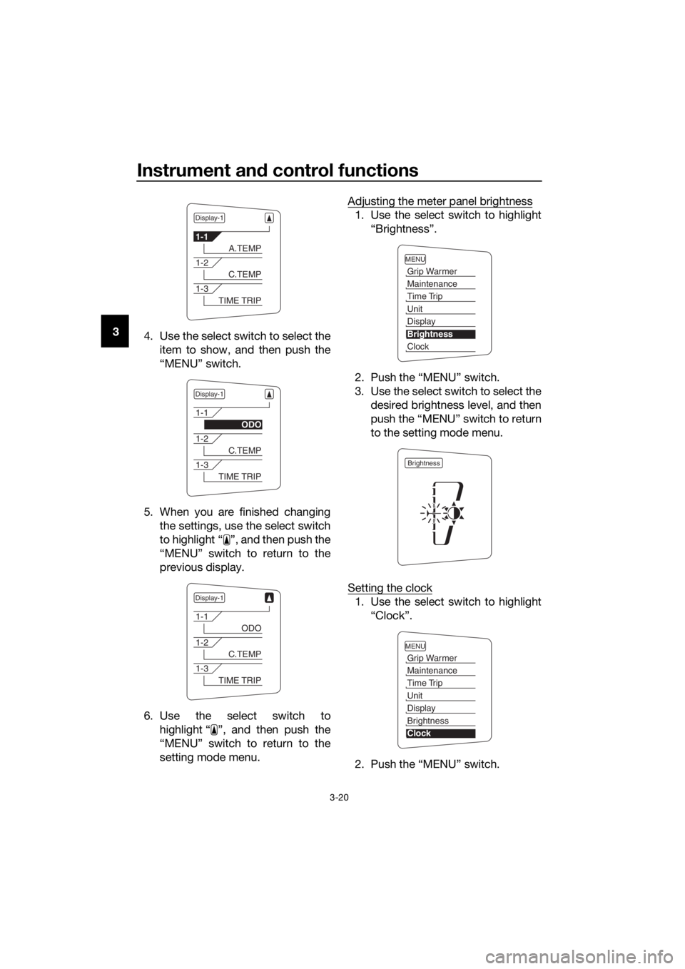
4. Use the select switch to select the
item to show, and then push the
ŌĆ£MENUŌĆØ switch.
5. When you are finished changing the settings, use the select switch
to highlight ŌĆ£ ŌĆØ, and then push the
ŌĆ£MENUŌĆØ switch to return to the
previous display.
6. Use the select switch to highlight ŌĆ£ ŌĆØ, and then push the
ŌĆ£MENUŌĆØ switch to return to the
setting mode menu. Adjusting the meter panel brightness
1. Use the select switch to highlight
ŌĆ£BrightnessŌĆØ.
2. Push the ŌĆ£MENUŌĆØ switch.
3. Use the select switch to select the desired brightness level, and then
push the ŌĆ£MENUŌĆØ switch to return
to the setting mode menu.
Setting the clock
1. Use the select switch to highlight ŌĆ£ClockŌĆØ.
2. Push the ŌĆ£MENUŌĆØ switch.
Display-1
1-1
A.TEMP
1-2
C.TEMP
1-3
TIME TRIP
Display-1
1-1
ODO
1-2
C.TEMP
1-3
TIME TRIP
Display-1
1-1
ODO
1-2
C.TEMP
1-3
TIME TRIP
MENU
Grip Warmer
Maintenance
Time Trip
Unit
Display
Brightness
Clock
Brightness
MENU
Grip Warmer
Maintenance
Time Trip
Unit
Display
Brightness
Clock
UB95E2E0.book Page 20 Tuesday, December 17, 2019 10:29 AM
Page 35 of 122
Instrument and control functions
3-21
3
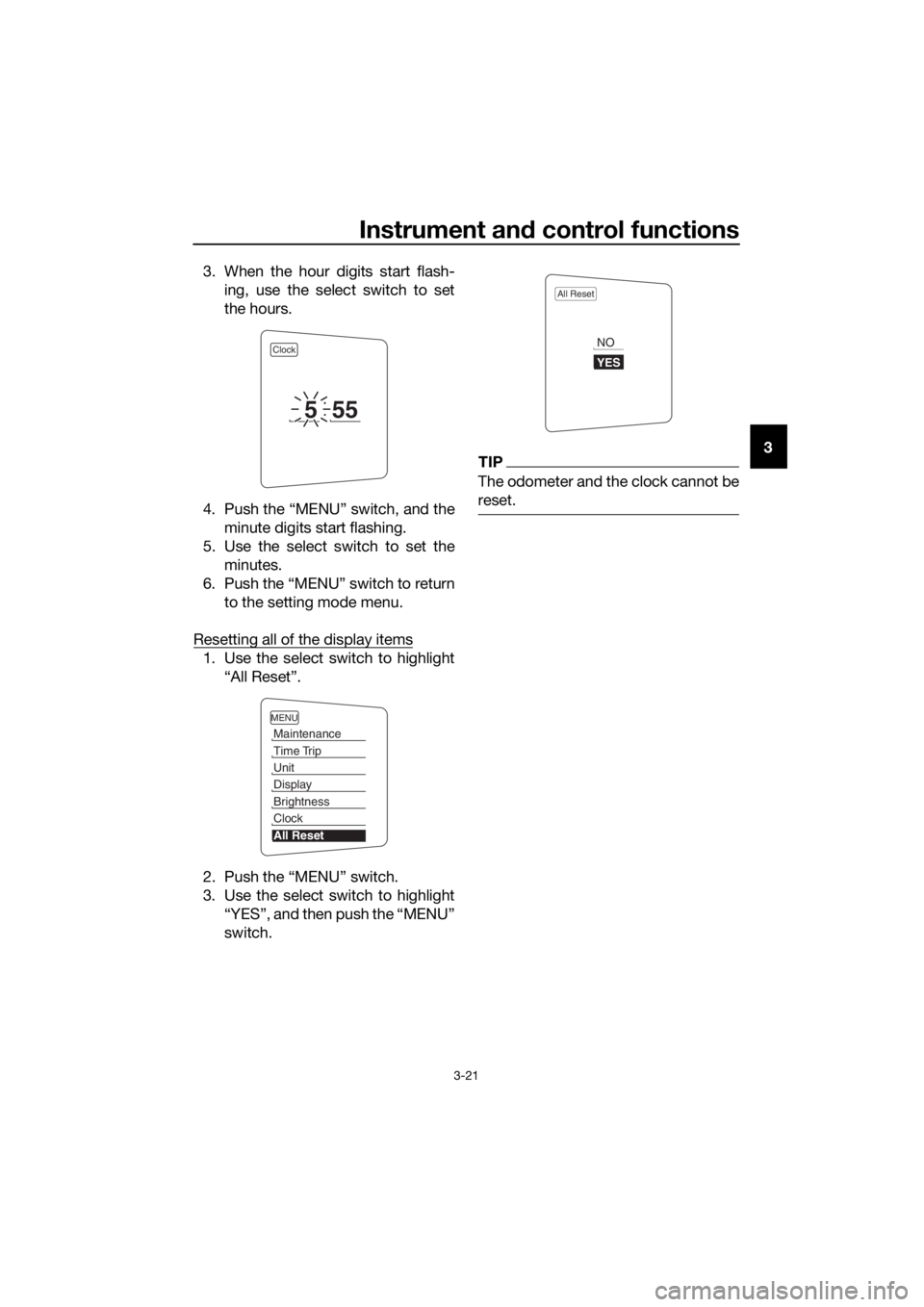
3. When the hour digits start flash-
ing, use the select switch to set
the hours.
4. Push the ŌĆ£MENUŌĆØ switch, and the minute digits start flashing.
5. Use the select switch to set the minutes.
6. Push the ŌĆ£MENUŌĆØ switch to return to the setting mode menu.
Resetting all of the display items
1. Use the select switch to highlight ŌĆ£All ResetŌĆØ.
2. Push the ŌĆ£MENUŌĆØ switch.
3. Use the select switch to highlight ŌĆ£YESŌĆØ, and then push the ŌĆ£MENUŌĆØ
switch.
TIP
The odometer and the clock cannot be
reset.
Clock
555
MENU
Maintenance
Time Trip
Unit
Display
Brightness
Clock
All Reset
All Reset
YES
NO
UB95E2E0.book Page 21 Tuesday, December 17, 2019 10:29 AM
Page 44 of 122
Instrument and control functions
3-30
3
EAU13077
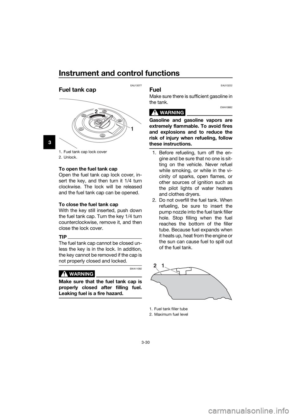
Fuel tank cap
To open the fuel tank cap
Open the fuel tank cap lock cover, in-
sert the key, and then turn it 1/4 turn
clockwise. The lock will be released
and the fuel tank cap can be opened.
To close the fuel tank cap
With the key still inserted, push down
the fuel tank cap. Turn the key 1/4 turn
counterclockwise, remove it, and then
close the lock cover.
TIP
The fuel tank cap cannot be closed un-
less the key is in the lock. In addition,
the key cannot be removed if the cap is
not properly closed and locked.
WARNING
EWA11092
Make sure that the fuel tank cap is
properly close d after fillin g fuel.
Leakin g fuel is a fire hazar d.
EAU13222
Fuel
Make sure there is sufficient gasoline in
the tank.
WARNING
EWA10882
Gasoline an d gasoline vapors are
extremely flammab le. To avoid fires
an d explosions an d to re duce the
risk of injury when refueling , follow
these instructions.
1. Before refueling, turn off the en- gine and be sure that no one is sit-
ting on the vehicle. Never refuel
while smoking, or while in the vi-
cinity of sparks, open flames, or
other sources of ignition such as
the pilot lights of water heaters
and clothes dryers.
2. Do not overfill the fuel tank. When refueling, be sure to insert the
pump nozzle into the fuel tank filler
hole. Stop filling when the fuel
reaches the bottom of the filler
tube. Because fuel expands when
it heats up, heat from the engine or
the sun can cause fuel to spill out
of the fuel tank.1. Fuel tank cap lock cover
2. Unlock.
1
2
1. Fuel tank filler tube
2. Maximum fuel level
21
UB95E2E0.book Page 30 Tuesday, December 17, 2019 10:29 AM
Page 47 of 122
Instrument and control functions
3-33
3
EAU39496
Seats
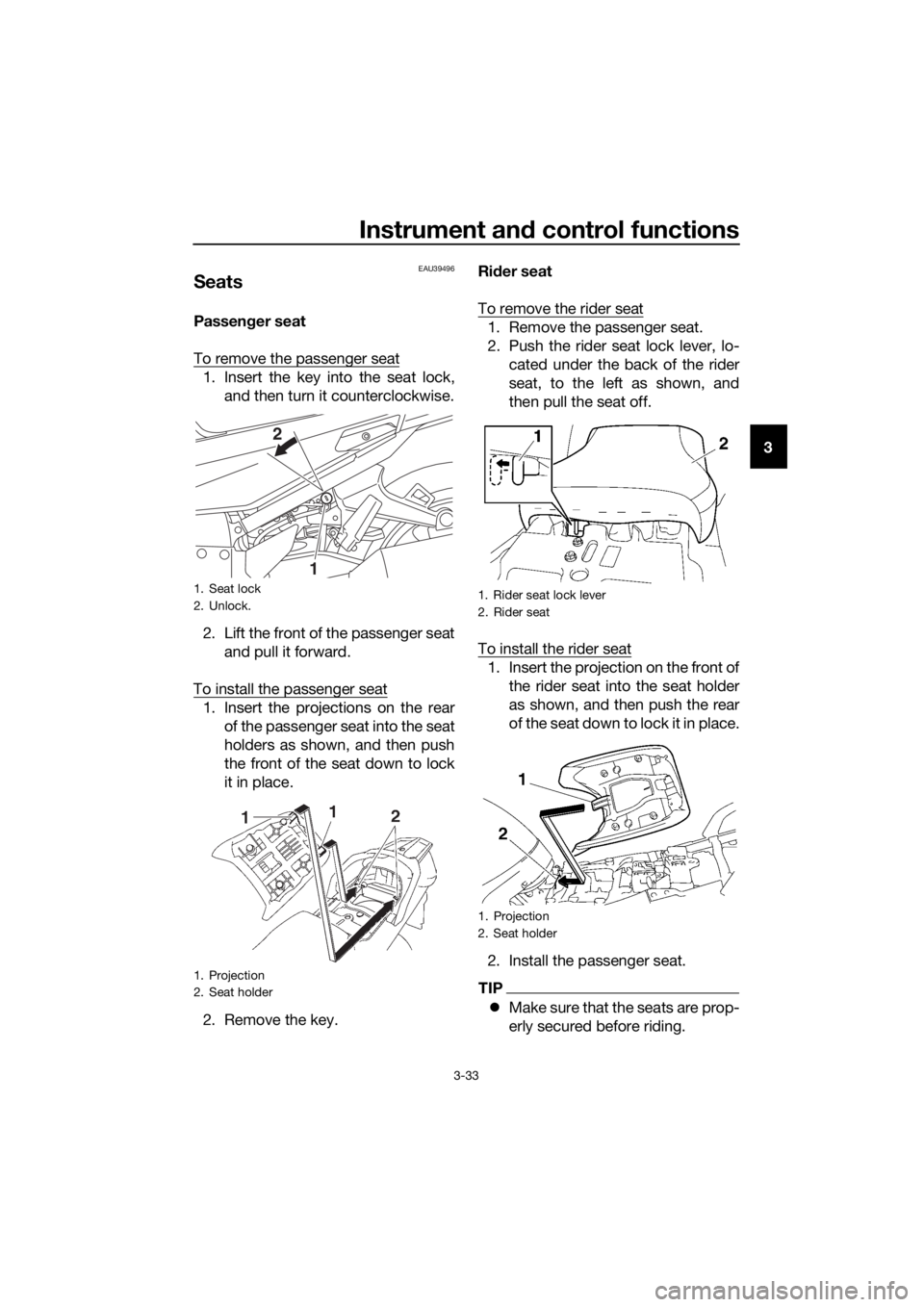
Passen ger seat
To remove the passenger seat
1. Insert the key into the seat lock, and then turn it counterclockwise.
2. Lift the front of the passenger seat and pull it forward.
To install the passenger seat
1. Insert the projections on the rear of the passenger seat into the seat
holders as shown, and then push
the front of the seat down to lock
it in place.
2. Remove the key. Ri
der seat
To remove the rider seat
1. Remove the passenger seat.
2. Push the rider seat lock lever, lo- cated under the back of the rider
seat, to the left as shown, and
then pull the seat off.
To install the rider seat
1. Insert the projection on the front of the rider seat into the seat holder
as shown, and then push the rear
of the seat down to lock it in place.
2. Install the passenger seat.
TIP
’ü¼ Make sure that the seats are prop-
erly secured before riding.
1. Seat lock
2. Unlock.
1. Projection
2. Seat holder
1
2
1. Rider seat lock lever
2. Rider seat
1. Projection
2. Seat holder
UB95E2E0.book Page 33 Tuesday, December 17, 2019 10:29 AM