coolant level YAMAHA FJR1300AS 2020 Owners Manual
[x] Cancel search | Manufacturer: YAMAHA, Model Year: 2020, Model line: FJR1300AS, Model: YAMAHA FJR1300AS 2020Pages: 122, PDF Size: 3.42 MB
Page 5 of 122

Table of contents
Safety information ............................1-1
Description ........................................2-1
Left view ..........................................2-1
Right view........................................2-2
Controls and instruments ................2-3
Instrument an d control functions ....3-1
Immobilizer system .........................3-1
Main switch/steering lock ...............3-2
Indicator lights and warning lights ............................................3-3
Cruise control system .....................3-6
Multi-function meter unit .................3-9
D-mode (drive mode) ....................3-22
Handlebar switches.......................3-22
YCC-S system...............................3-24
Shift pedal .....................................3-25
Hand shift lever .............................3-26
Brake lever ....................................3-26
Brake pedal ...................................3-27
ABS ...............................................3-27
Traction control system.................3-28
Fuel tank cap.................................3-30
Fuel................................................3-30
Fuel tank overflow hose ................3-32
Catalytic converter ........................3-32
Seats .............................................3-33
Adjusting the rider seat height ......3-34
Storage compartment ...................3-36
Accessory box...............................3-37
Adjusting the headlight beams......3-38
Handlebar position ........................3-39
Opening and closing the cowling vents ..........................................3-39
Rear view mirrors ..........................3-41
Adjusting the front and rear suspension.................................3-41
Auxiliary DC jack ..........................3-46
Sidestand ......................................3-47
Ignition circuit cut-off system........3-47
Cornering lights .............................3-49 For your safety – pre-operation
checks
............................................... 4-1
Operation an d important ri din g
points ................................................. 5-1
Engine break-in ............................... 5-1
Starting the engine.......................... 5-2
Shifting ............................................ 5-4
Tips for reducing fuel consumption................................ 5-6
Parking ............................................ 5-6
Perio dic maintenance an d
a d justment ........................................ 6-1
Tool kit ............................................ 6-2
Periodic maintenance charts .......... 6-3
Periodic maintenance chart for the emission control system.............. 6-3
General maintenance and lubrication chart........................... 6-4
Removing and installing panels ...... 6-7
Checking the spark plugs ............. 6-10
Canister......................................... 6-11
Engine oil and oil filter cartridge ... 6-11
Why Yamalube .............................. 6-14
Final gear oil.................................. 6-15
Coolant ......................................... 6-16
Air filter element ............................ 6-18
Checking the engine idling speed......................................... 6-18
Checking the throttle grip free play ............................................ 6-19
Valve clearance ............................. 6-19
Tires .............................................. 6-20
Cast wheels .................................. 6-22
YCC-S clutch ................................ 6-23
Checking the brake lever free play ............................................ 6-23
Brake light switches ...................... 6-24
Checking the front and rear brake pads........................................... 6-24
Checking the brake and YCC-S clutch fluid levels ....................... 6-25
Changing the brake and YCC-S clutch fluids ............................... 6-27
UB95E2E0.book Page 1 Tuesday, December 17, 2019 10:29 AM
Page 12 of 122
Description
2-1
2
EAU63371
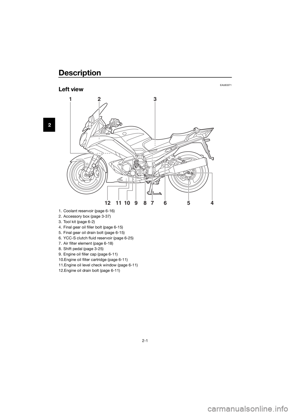
Left view
12
3
4
65
789101112
1. Coolant reservoir (page 6-16)
2. Accessory box (page 3-37)
3. Tool kit (page 6-2)
4. Final gear oil filler bolt (page 6-15)
5. Final gear oil drain bolt (page 6-15)
6. YCC-S clutch fluid reservoir (page 6-25)
7. Air filter element (page 6-18)
8. Shift pedal (page 3-25)
9. Engine oil filler cap (page 6-11)
10.Engine oil filter cartridge (page 6-11)
11.Engine oil level check window (page 6-11)
12.Engine oil drain bolt (page 6-11)
UB95E2E0.book Page 1 Tuesday, December 17, 2019 10:29 AM
Page 64 of 122
For your safety – pre-operation checks
4-1
4
EAU63441
Inspect your vehicle each time you use it to make sure the vehicle is in safe oper-
ating condition. Always follow the inspection and maintenance procedures and
schedules described in the Owner’s Manual.
WARNING
EWA11152
Failure to inspect or maintain the vehicle properly increases the possibility
of an acci dent or equipment d amage. Do not operate the vehicle if you fin d
any pro blem. If a pro blem cannot be correcte d b y the proce dures provi ded
in this manual, have the vehicle inspecte d b y a Yamaha dealer.
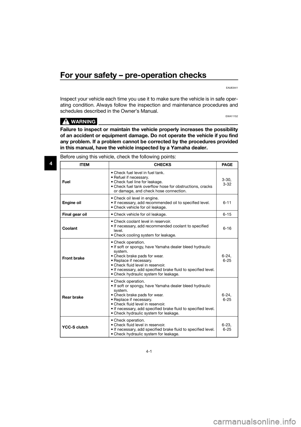
Before using this vehicle, check the following points:
ITEM CHECKSPAGE
Fuel • Check fuel level in fuel tank.
• Refuel if necessary.
• Check fuel line for leakage.
• Check fuel tank overflow hose for obstructions, cracks
or damage, and check hose connection. 3-30,
3-32
En gine oil • Check oil level in engine.
• If necessary, add recommended oil to specified level.
• Check vehicle for oil leakage. 6-11
Final gear oil • Check vehicle for oil leakage. 6-15
Coolant • Check coolant level in reservoir.
• If necessary, add recommended coolant to specified
level.
• Check cooling system for leakage. 6-16
Front brake • Check operation.
• If soft or spongy, have Yamaha dealer bleed hydraulic
system.
• Check brake pads for wear.
• Replace if necessary.
• Check fluid level in reservoir.
• If necessary, add specified brake fluid to specified level.
• Check hydraulic system for leakage. 6-24,
6-25
Rear brake • Check operation.
• If soft or spongy, have Yamaha dealer bleed hydraulic
system.
• Check brake pads for wear.
• Replace if necessary.
• Check fluid level in reservoir.
• If necessary, add specified brake fluid to specified level.
• Check hydraulic system for leakage. 6-24,
6-25
YCC-S clutch • Check operation.
• Check fluid level in reservoir.
• If necessary, add specified brake fluid to specified level.
• Check hydraulic system for leakage. 6-23,
6-25
UB95E2E0.book Page 1 Tuesday, December 17, 2019 10:29 AM
Page 76 of 122
Periodic maintenance an d a djustment
6-5
6
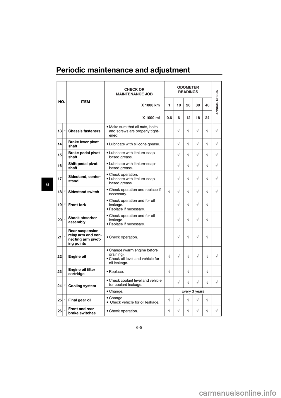
13 *Chassis fasteners • Make sure that all nuts, bolts
and screws are properly tight-
ened. √√√√√
14 Brake lever pivot
shaft
• Lubricate with silicone grease.
√√√√√
15 Brake pe
dal pivot
shaft • Lubricate with lithium-soap-
based grease. √√√√√
16 Shift pe
dal pivot
shaft • Lubricate with lithium-soap-
based grease. √√√√√
17 Si
destan d, center-
stan d • Check operation.
• Lubricate with lithium-soap-
based grease. √√√√√
18 *Sidestan d switch • Check operation and replace if
necessary. √√√√√√
19 *Front fork • Check operation and for oil
leakage.
• Replace if necessary. √√√√
20 *Shock ab
sorber
assem bly • Check operation and for oil
leakage.
• Replace if necessary. √√√√
21 *Rear suspension
relay arm an
d con-
nectin g arm pivot-
in g points • Check operation.
√√√√
22 En gine oil • Change (warm engine before
draining).
• Check oil level and vehicle for oil leakage. √√√√√√
23 En
gine oil filter
cartri dge • Replace.
√√√
24 *Co
olin g syst
em• Check coolant level and vehicle
for coolant leakage. √√√√√
• Change. Every 3 years
25 *Final gear oil • Change.
• Check vehicle for oil leakage. √√√√√
26 *Front an
d rear
b rake switches • Check operation.
√√√√√√
NO. ITEM
X 1000 km
CHECK OR
MAINTENANCE JOB
X 1000 mi ODOMETER
READINGS
ANNUAL CHECK
110203040
0.6 6 12 18 24
UB95E2E0.book Page 5 Tuesday, December 17, 2019 10:29 AM
Page 87 of 122
Periodic maintenance an d a djustment
6-16
6
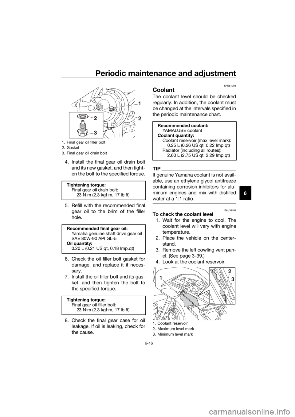
4. Install the final gear oil drain bolt
and its new gasket, and then tight-
en the bolt to the specified torque.
5. Refill with the recommended final gear oil to the brim of the filler
hole.
6. Check the oil filler bolt gasket for damage, and replace it if neces-
sary.
7. Install the oil filler bolt and its gas- ket, and then tighten the bolt to
the specified torque.
8. Check the final gear case for oil leakage. If oil is leaking, check for
the cause.
EAUS1203
Coolant
The coolant level should be checked
regularly. In addition, the coolant must
be changed at the intervals specified in
the periodic maintenance chart.
TIP
If genuine Yamaha coolant is not avail-
able, use an ethylene glycol antifreeze
containing corrosion inhibitors for alu-
minum engines and mix with distilled
water at a 1:1 ratio.
EAU54164To check the coolant level1. Wait for the engine to cool. The coolant level will vary with engine
temperature.
2. Place the vehicle on the center- stand.
3. Remove the left cowling vent pan- el. (See page 3-39.)
4. Look at the coolant reservoir.
1. Final gear oil filler bolt
2. Gasket
3. Final gear oil drain bolt
Ti ghtening torque:
Final gear oil drain bolt:
23 N·m (2.3 kgf·m, 17 lb·ft)
Recommen ded final gear oil:
Yamaha genuine shaft drive gear oil
SAE 80W-90 API GL-5
Oil quantity:
0.20 L (0.21 US qt, 0.18 Imp.qt)
Ti ghtening torque:
Final gear oil filler bolt: 23 N·m (2.3 kgf·m, 17 lb·ft)
1
2
32
Recommen ded coolant:
YAMALUBE coolant
Coolant quantity: Coolant reservoir (max level mark): 0.25 L (0.26 US qt, 0.22 Imp.qt)
Radiator (including all routes): 2.60 L (2.75 US qt, 2.29 Imp.qt)
1. Coolant reservoir
2. Maximum level mark
3. Minimum level mark
2
1 3
UB95E2E0.book Page 16 Tuesday, December 17, 2019 10:29 AM
Page 88 of 122
Periodic maintenance an d a djustment
6-17
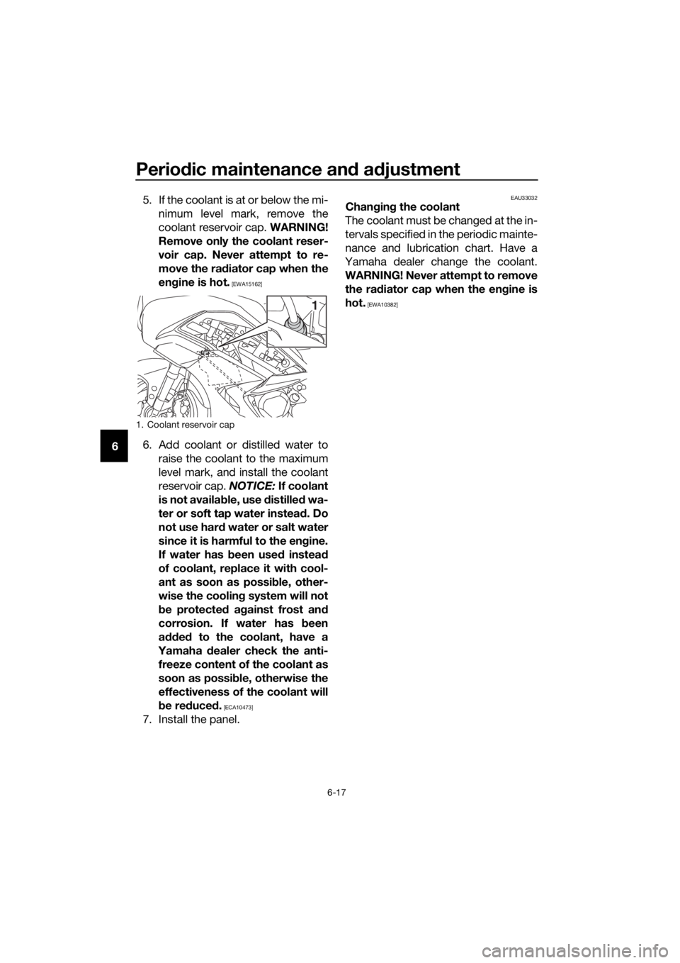
6 5. If the coolant is at or below the mi-
nimum level mark, remove the
coolant reservoir cap. WARNING!
Remove only the coolant reser-
voir cap. Never attempt to re-
move the ra diator cap when the
en gine is hot.
[EWA15162]
6. Add coolant or distilled water to
raise the coolant to the maximum
level mark, and install the coolant
reservoir cap. NOTICE: If coolant
is not availa ble, use distille d wa-
ter or soft tap water instea d. Do
not use har d water or salt water
since it is harmful to the en gine.
If water has been used instead
of coolant, replace it with cool-
ant as soon as possi ble, other-
wise the coolin g system will not
b e protecte d a gainst frost an d
corrosion. If water has been
a dde d to the coolant, have a
Yamaha dealer check the anti-
freeze content of the coolant as
soon as possi ble, otherwise the
effectiveness of the coolant will
b e re duce d.
[ECA10473]
7. Install the panel.
EAU33032Chan gin g the coolant
The coolant must be changed at the in-
tervals specified in the periodic mainte-
nance and lubrication chart. Have a
Yamaha dealer change the coolant.
WARNING! Never attempt to remove the ra diator cap when the en gine is
hot.
[EWA10382]
1. Coolant reservoir cap
1
UB95E2E0.book Page 17 Tuesday, December 17, 2019 10:29 AM
Page 114 of 122
Specifications
8-1
8
Dimensions:
Overall length:2230 mm (87.8 in)
Overall width:
750 mm (29.5 in)
Overall height: 1325/1455 mm (52.2/57.3 in)
Seat height: 805/825 mm (31.7/32.5 in)
Wheelbase:
1545 mm (60.8 in)
Ground clearance: 125 mm (4.92 in)
Minimum turning radius: 3.2 m (10.50 ft)
Wei ght:
Curb weight:
296 kg (653 lb)
Engine:
Combustion cycle:
4-stroke
Cooling system:
Liquid cooled
Valve train: DOHC
Cylinder arrangement: Inline
Number of cylinders:
4-cylinder
Displacement: 1298 cm³
Bore × stroke:
79.0 × 66.2 mm (3.11 × 2.61 in)
Starting system:
Electric starter
Engine oil:
Recommended brand:
SAE viscosity grades:
10W-40
Recommended engine oil grade: API service SG type or higher, JASO
standard MA
Engine oil quantity: Oil change:3.80 L (4.02 US qt, 3.34 Imp.qt) With oil filter removal:
4.00 L (4.23 US qt, 3.52 Imp.qt)
Final gear oil:
Type:
Yamaha genuine shaft drive gear oil SAE
80W-90 API GL-5
Quantity:
0.20 L (0.21 US qt, 0.18 Imp.qt)
Coolant quantity:
Coolant reservoir (up to the maximum level
mark):0.25 L (0.26 US qt, 0.22 Imp.qt)
Radiator (including all routes): 2.60 L (2.75 US qt, 2.29 Imp.qt)
Fuel:
Recommended fuel:
Unleaded gasoline (E10 acceptable)
Octane number (RON): 90
Fuel tank capacity: 25 L (6.6 US gal, 5.5 Imp.gal)
Fuel reserve amount:
5.5 L (1.45 US gal, 1.21 Imp.gal)
Fuel injection:
Throttle body:ID mark: B881 00
Drivetrain:
Gear ratio:
1st:2.500 (35/14)
2nd:
1.722 (31/18)
3rd: 1.350 (27/20)
4th: 1.111 (30/27)
5th:
0.963 (26/27)
6th: 0.846 (22/26)
Front tire:
Type:
Tubeless
Size: 120/70ZR17M/C (58W)
Manufacturer/model: BRIDGESTONE/BT023F E
UB95E2E0.book Page 1 Tuesday, December 17, 2019 10:29 AM
Page 119 of 122

10-1
10
Index
A
ABS ...................................................... 3-27
ABS warning light ................................... 3-4
Accessory box...................................... 3-37
Air filter element ................................... 6-18
Auxiliary DC jack .................................. 3-46
B
Battery .................................................. 6-31
Brake and shift pedals, checking and
lubricating .......................................... 6-28
Brake and YCC-S clutch fluid levels, checking............................................. 6-25
Brake and YCC-S clutch fluids, changing ............................................ 6-27
Brake lever ........................................... 3-26
Brake lever, checking and lubricating .......................................... 6-29
Brake lever free play, checking ............ 6-23
Brake light switches ............................. 6-24
Brake pedal .......................................... 3-27
C
Cables, checking and lubricating ......... 6-27
Canister ................................................ 6-11
Care ........................................................ 7-1
Catalytic converter ............................... 3-32
Centerstand and sidestand, checking and lubricating ................................... 6-29
Coolant ................................................. 6-16
Cornering lights .................................... 3-49
Cowling vents, opening and closing .... 3-39
Cruise control indicator lights ................ 3-4
Cruise control switches ........................ 3-23
Cruise control system ............................ 3-6
D
Data recording, vehicle .......................... 9-3
Diagnostic connector ............................. 9-2
Dimmer/Pass switch ............................ 3-22
D-mode (drive mode) ........................... 3-22
E
Engine break-in ...................................... 5-1
Engine idling speed, checking ............. 6-18
Engine oil and oil filter cartridge ........... 6-11
Engine overheating............................... 6-37
Engine serial number.............................. 9-1
Engine trouble warning light................... 3-4
F
Final gear oil ......................................... 6-15
Front and rear brake pads, checking ... 6-24
Front fork, checking ............................. 6-30
Fuel....................................................... 3-30 Fuel consumption, tips for reducing ....... 5-6
Fuel tank cap ........................................ 3-30
Fuel tank overflow hose ........................ 3-32
Fuses, replacing.................................... 6-33
H
Handlebar position, adjusting ............... 3-39
Handlebar switches .............................. 3-22
Hand shift lever ..................................... 3-26
Hazard switch ....................................... 3-23
Headlight beams, adjusting .................. 3-38
High beam indicator light........................ 3-3
Horn switch........................................... 3-23
I
Identification numbers ............................ 9-1
Ignition circuit cut-off system ............... 3-47
Immobilizer system ................................. 3-1
Immobilizer system indicator light .......... 3-5
Indicator lights and warning lights .......... 3-3
M
Main switch/steering lock ....................... 3-2
Maintenance and lubrication, periodic ... 6-4
Maintenance, emission control
system .................................................. 6-3
Matte color, caution ................................ 7-1
Menu switch ......................................... 3-23
Model label ............................................. 9-1
Multi-function meter unit ........................ 3-9
N
Neutral indicator light.............................. 3-3
O
Oil level warning light .............................. 3-4
P
Panels, removing and installing .............. 6-7
Parking .................................................... 5-6
Part locations .......................................... 2-1
R
Rear view mirrors .................................. 3-41
Rider seat height, adjusting .................. 3-34
S
Safety information................................... 1-1
Seats ..................................................... 3-33
Select switch ........................................ 3-23
Shift down indicator light ........................ 3-5
Shifting .................................................... 5-4
Shift pedal............................................. 3-25
Sidestand .............................................. 3-47
Spark plugs, checking .......................... 6-10
Specifications ......................................... 8-1
Starting the engine.................................. 5-2
Steering, checking ................................ 6-30
UB95E2E0.book Page 1 Tuesday, December 17, 2019 10:29 AM