cruise YAMAHA FX HO 2013 Owners Manual
[x] Cancel search | Manufacturer: YAMAHA, Model Year: 2013, Model line: FX HO, Model: YAMAHA FX HO 2013Pages: 116, PDF Size: 5.56 MB
Page 1 of 116

Read this manual carefully
before operating this watercraft.
OWNER’S/OPERATOR’S MANUAL
2013 WaveRunner
FX SHO
FX Cruiser SHO
F2S-F8199-71-E0
UF2S71E0.book Page 1 Tuesday, August 21, 2012 2:33 PM
Page 3 of 116

with the requirements of Directive 94/25/EC, as amended by Directive 200\
3/44/EC
Name of Engine Manufactu")
Important manual information
EJU37155
Declaration of Conformity for Personal Watercraft (PWC)
with the requirements of Directive 94/25/EC, as amended by Directive 200\
3/44/EC
Name of Engine Manufacturer: YAMAHA MOTOR CO., LTD.
Name / Title:H. Yamaji / President of YAMAHA MOTOR EUROPE N.V.
Address:
2500 Shingai, Iwata, Shizuoka 438-8501, Japan
Name of Authorised Representative: YAMAHA MOTOR EUROPE N.V.
Address: Koolhovenlaan 101, 1119 NC Schiphole-Rijk, The Netherlands
Name of Notified Body for exhaust and noise emission assessment: Luxcontrol SA
Address: 1. avenue des Terres Rouges BP 349, Esch-sur-Alzette, L-4004. Luxembourg\
Name of Notified Body for exhaust and noise emission assessment: SNCH
FA1800A-M / FX Cruiser SHO, FA1800-M / FX SHO 0882
0499
ID Number:
ID Number:
Address: 11, route de Luxembourg BP 32, Sandweiler, L-5230. Luxembourg
U S-Y A M A 1 0 0 1 I 2 1 3
Conformity assessment module used:
for construction:
for exhaust emissions:
for noise emissions:
DESCRIPTION OF CRAFT
DESCRIPTION OF ENGINE A
A
Craft model Identification Number, starting from :
Model name / Commercial name : C
Design Category : Other Community Directives applied
Directive 2004/108/EC relating to electromagnetic compatibility (EMC).\
CISPR 12
Directive 2006/42/EC relating to Machinery. Standards
EN 61000-6-2
D
Aa
AaB+C
B+CB+D
B+D B+E
B+EB+F
B+FG
G
GH
H
H
Engine Type:
PWC engine Combustion cycle:
4 stroke
Fuel Type:
Petrol
ESSENTIAL REQUIREMENTS
IDENTIFICATION OF ENGINE COVERED BY THIS DECLARATION OF CONFORMITY
Name of engine model
6CS Name / ID number of Notified Body
SNCH / 0499
EC Type–examination certificate number
SNCH*94/25*2003/44*0043*01
(identification of the person empowered to sign on behalf of the engine\
manufacturer or his authorised representative)
Signature and title:(or an equivalent marking)Date and place of issue:1st / October / 2012, Schiphol-Rijk, The Netherlands
Essential requirements
standardsother normative
document / method technical filePlease specify in more detail
(* = mandatory standard)
I.A design and construction EN ISO 13590
I.B exhaust emission *EN ISO 8178-1
I.C noise emission *EN ISO 14509
*
*
This declaration of conformity is issued under the sole responsibility o\
f the PWC manufacturer. I declare on behalf of the PWC
manufacturer that the craft model and engine(s) mentioned above compli\
es (comply) with all applicable essential
requirements in the way specified and is (are) in conformity with the \
type(s) for which above mentioned EC type-examination
certificate(s) has (have) been issued.
ID Number:
ID Number:
UF2S71E0.book Page 1 Tuesday, August 21, 2012 2:33 PM
Page 4 of 116

Important manual information
EJU30192
To the owner/operator
Thank you for choosing a Yamaha watercraft.
This owner’s/operator’s manual contains in-
formation you will need for proper operation,
maintenance, and care. If you have any ques-
tions about the operation or maintenance of
your watercraft, please consult a Yamaha
dealer.
This manual is not a course on boating safety
or seamanship. If this is your first watercraft,
or if you are changing to a type of watercraft
you are not familiar with, for your own comfort
and safety, please ensure that you obtain
proper training or practice before operating
the watercraft by yourself. In addition, a
Yamaha dealer or boating organization will be pleased to recommend local sea schools, or
competent instructors.
In this manual, information of particular impor-
tance is distinguished in the following ways:
This is the safety alert symbol. It is used
to alert you to potential personal injury haz-
ards. Obey all safety messages that follow
this symbol to avoid possible injury or death.
WARNING
EWJ00071
A WARNING indicates a hazardous situa-
tion which, if not avoided, could result in
death or serious injury.
NOTICE
ECJ00091
A NOTICE indicates special precautions
that must be taken to avoid damage to the
watercraft or other property.
TIP:
A TIP provides key information to make pro-
cedures easier or clearer.
EJU40410
Because Yamaha has a policy of continuing
product improvement, this product may not be
exactly as described in this owner’s/opera-
tor’s manual. Specifications are subject to
change without notice.
This manual should be considered a perma-
nent part of this watercraft and should remain
with it even if the watercraft is subsequently
sold.
EJU30232
WaveRunner FX SHO/FX Cruiser SHO OWNER’S/OPERATOR’S MANUAL©2012 by Yamaha Motor Co., Ltd.
1st Edition, August 2012All rights reserved.
Any reprinting or unauthorized use
without the written permission of Yamaha Motor Co., Ltd.
is expressly prohibited.
Printed in U.S.A.
UF2S71E0.book Page 2 Tuesday, August 21, 2012 2:33 PM
Page 5 of 116

Table of contents
General and important labels ........... 1Identification numbers .................... 1
Primary Identification (PRI-ID)
number ........................................... 1
Craft Identification Number (CIN) ...... 1
Engine serial number ........................ 1
Manufactured date label .................... 2
Model information ........................... 2
Builder’s plate .................................... 2
Important labels .............................. 4
Warning labels ................................... 5
Other labels ....................................... 9
Safety information ........................... 11 Limitations on who may operate the watercraft ............................ 11
Cruising limitations ....................... 12
Operation requirements ............... 13
Recommended equipment ........... 15
Hazard information ....................... 16
Watercraft characteristics ............. 16
Water-skiing ................................. 18
Safe boating rules ........................ 19
Enjoy your watercraft responsibly ................................ 20
Description....................................... 21 Watercraft glossary ...................... 21
Location of main components ...... 22
Control function operation ............. 26 Watercraft control functions ......... 26
Remote control transmitter .............. 26
Yamaha Security System ................ 27
Engine stop switch .......................... 28
Engine shut-off switch ..................... 28
Start switch ...................................... 28
Throttle lever ................................... 29
Steering system ............................... 29
Adjustable tilt steering system ......... 30
Cooling water pilot outlets ............... 30
Water separator ............................... 31
Watercraft operation ....................... 32Watercraft operation functions ..... 32
Shift system ..................................... 32
Quick Shift Trim System
(Q.S.T.S.) ..................................... 33
Watercraft operation modes ......... 35
Low RPM Mode ............................... 35
No-wake mode ................................ 36
Cruise assist .................................... 37
Instrument operation ...................... 40Multifunction information center ... 40
Analog speedometer/tachometer .... 40
Information display .......................... 41
Multifunction display
(FX Cruiser SHO) ......................... 45
Equipment operation ...................... 49Equipment .................................... 49
Seats ............................................... 49
Handgrip .......................................... 50
Reboarding grip ............................... 50
Reboarding step .............................. 50
Bow eye ........................................... 51
Stern eyes ....................................... 51
Cleat ................................................ 51
Pull-up cleats (FX Cruiser SHO) ...... 52
Storage compartments .................... 52
Fire extinguisher holder and
cover ............................................ 57
Operation and handling
requirements ................................... 58Fuel requirements ........................ 58
Fuel ................................................. 58
Engine oil requirements ............... 60
Engine oil ......................................... 60
Draining the bilge water ............... 61
Draining the bilge water on land ...... 61
Draining the bilge water on water .... 62
UF2S71E0.book Page 1 Tuesday, August 21, 2012 2:33 PM
Page 7 of 116

General and important labels
1
EJU36451
Identification numbers
Record the Primary Identification (PRI-ID)
number, Craft Identification Number (CIN),
and engine serial number in the spaces pro-
vided for assistance when ordering spare
parts from a Yamaha dealer. Also record and
keep these ID numbers in a separate place in
case your watercraft is stolen.
EJU42520Primary Identification (PRI-ID) number
The PRI-ID number is stamped on a plate at-
tached inside the engine compartment. (See
page 49 for seat removal and installation pro-
cedures and page 55 for information on the
removable watertight storage compartment.)
MODEL:
FA1800-M (FX SHO)
FA1800A-M (FX Cruiser SHO)
EJU36550Craft Identification Number (CIN)
The CIN is stamped on a plate attached to the
aft deck.
EJU40470Engine serial number
The engine serial number is stamped on a
plate attached to the engine unit. (See page
49 for seat removal and installation proce-
dures and page 94 for engine cover removal
and installation procedures.)
1Primary Identification (PRI-ID) number loca-
tion
1
MODELF2S
F
PRI-I.D.
YAMAHA MOTOR CO., LTD.
ASSEMBLED IN U.S.A. FROM AMERICAN AND JAPANESE
COMPONENTS.
ASSEMBLÉ AUX ÉTATS-UNIS DE PIÈCES AMÉRICAINES ET
JAPONAISES.
2S
1Craft Identification Number (CIN) location
1 Engine serial number location
1
1
UF2S71E0.book Page 1 Tuesday, August 21, 2012 2:33 PM
Page 28 of 116

Description
22
EJU31011
Location of main components
Exterior
7
8
9
10
11
2
1
3456
1Fuel filler cap (page 58)
2 Hood
3 Handlebars
4 Rear seat (page 49)
5 Front seat (page 49)
6 Footwell
7 Bow eye (page 51)
8 Hull
9 Cooling water pilot outlet (page 30)
10 Pull-up cleat (FX Cruiser SHO) (page 52)
11 Gunwale
UF2S71E0.book Page 22 Tuesday, August 21, 2012 2:33 PM
Page 30 of 116

Description
24
12
678 9
5
3411101213 14 15 1716
18 19 20 21
222324
1 Built-in watertight storage compartment
(page 55)
2 Start switch (page 28)
3 Engine shut-off switch (page 28)
4 Clip (page 28)
5 Remote control transmitter (page 26)
6 Q.S.T.S. selector lock lever (page 33)
7 Q.S.T.S. selector (page 33)
8 Engine stop switch (page 28)
9 Engine shut-off cord (lanyard) (page 28)
10 “VOLT/HOUR” button (page 40)
11 “SPEED/RPM” button (page 40)
12 “MODE/RESET” button (FX Cruiser SHO)
(page 40)
13 “START/STOP” button (FX Cruiser SHO)
(page 40)
14 Up switch (page 37)
15 Down switch (page 37)
16 Throttle lever (page 29)
17 Multifunction information center (page 40)
18 Glove compartment (page 53)
19 Removable beverage holder (page 55) 20
Tilt lever (page 30)
21 Shift lever (page 32)
22 “NO-WAKE MODE” switch (page 36)
23 “SET” switch (page 37)
24 Built-in beverage holder (page 55)
UF2S71E0.book Page 24 Tuesday, August 21, 2012 2:33 PM
Page 42 of 116

Watercraft operation
36
TIP:
If the remote control transmitter is operated
while the multifunction information center is in
the standby state, the center performs the ini-
tial operation, and then the setting is selected.
To activate the Low RPM Mode:
Push the “L-Mode” (unlock) button on the re-
mote control transmitter for more than 4 sec-
onds. Once the beeper sounds three times
and the “UNLOCK” indicator light blinks three
times, then comes on, the “L-MODE” indicator
light comes on and the Low RPM Mode is ac-
tivated.
TIP:
If the Low RPM Mode is activated immediate-
ly after the information display turns off, the
“L-MODE” indicator light will not come on. The
“L-MODE” indicator light will come on when
the engine is started.
To deactivate the Low RPM Mode:
Push the “L-Mode” (unlock) button on the re-
mote control transmitter for more than 4 sec- onds. Once the beeper sounds two times and
the “UNLOCK” indicator light blinks two times,
then comes on, the “L-MODE” indicator light
goes off and the Low RPM Mode is deactivat-
ed. When the Low RPM Mode is deactivated,
the watercraft returns to the normal operation
mode.
EJU42480No-wake mode
The no-wake mode is a function that main-
tains the engine speed at a fixed setting for
operating the watercraft at low speeds. This
function can be used only for forward opera-
tion of the watercraft.
TIP:
The no-wake mode can only be activated af-
ter 5 seconds have elapsed since starting the
engine.
Activating and deactivating the no-wake
mode
Activation of the no-wake mode will be con-
firmed by the number of beeps when the “NO-
WAKE MODE” switch is pushed, and by the
digital speedometer display of the multifunc-
tion information center. (See page 40 for infor-
mation on the multifunction information
center.)
TIP:
The beeps and the blinking digital speedome-
ter display also indicate the activation of the
cruise assist. (See page 37 for information on
the cruise assist.)
Number of
beeps Low RPM Mode
operation “L-
MODE”
indicator light
Activated Comes
on
Deactivated Goes off
1 “L-Mode” (unlock) button
2 “L-MODE” indicator light
2
L-Mode1Number
of beeps No-wake mode oper-
ation Digital
speedome- ter display
Activated Starts
blinking
Deactivated Stops
blinking
UF2S71E0.book Page 36 Tuesday, August 21, 2012 2:33 PM
Page 43 of 116
Watercraft operation
37
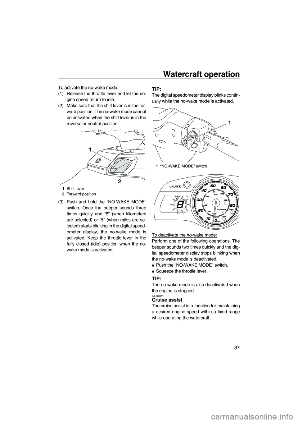
To activate the no-wake mode:
(1) Release the throttle lever and let the en-gine speed return to idle.
(2) Make sure that the shift lever is in the for- ward position. The no-wake mode cannot
be activated when the shift lever is in the
reverse or neutral position.
(3) Push and hold the “NO-WAKE MODE” switch. Once the beeper sounds three
times quickly and “8” (when kilometers
are selected) or “5” (when miles are se-
lected) starts blinking in the digital speed-
ometer display, the no-wake mode is
activated. Keep the throttle lever in the
fully closed (idle) position when the no-
wake mode is activated.TIP:
The digital speedometer display blinks contin-
ually while the no-wake mode is activated.
To deactivate the no-wake mode:
Perform one of the following operations. The
beeper sounds two times quickly and the dig-
ital speedometer display stops blinking when
the no-wake mode is deactivated.
●Push the “NO-WAKE MODE” switch.
●Squeeze the throttle lever.
TIP:
The no-wake mode is also deactivated when
the engine is stopped.
EJU37025Cruise assist
The cruise assist is a function for maintaining
a desired engine speed within a fixed range
while operating the watercraft.
1Shift lever
2 Forward position
1
2
1“NO-WAKE MODE” switch
1
UF2S71E0.book Page 37 Tuesday, August 21, 2012 2:33 PM
Page 44 of 116
Watercraft operation
38
TIP:
●The cruise assist can only be set between
engine speeds of approximately 3000 r/min
and approximately 7000 r/min.
●The cruise assist cannot be activated in the
Low RPM Mode. (See page 35 for Low
RPM Mode activation procedures.)
Activating and deactivating the cruise as-
sist
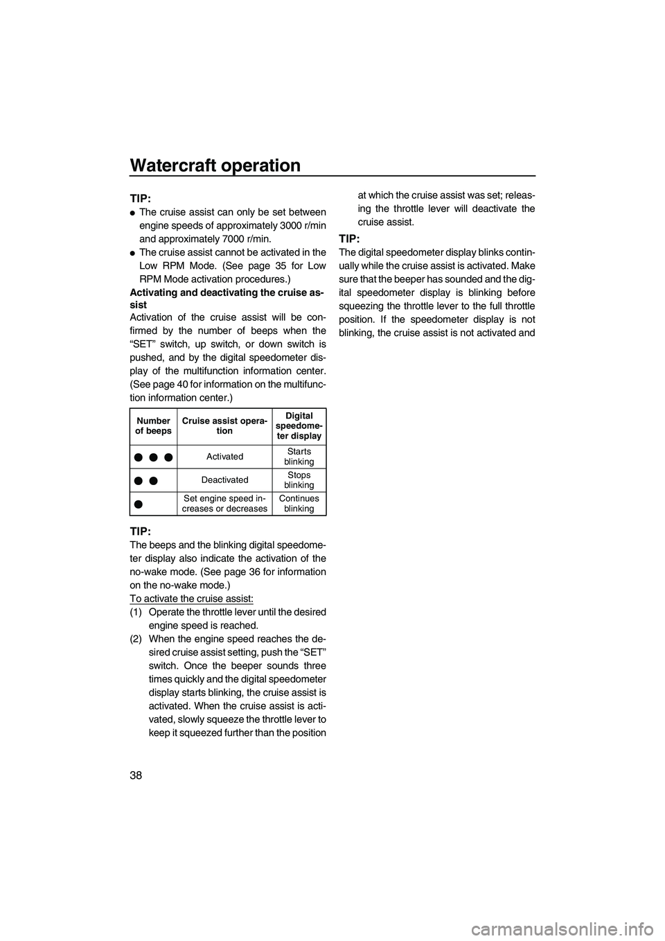
Activation of the cruise assist will be con-
firmed by the number of beeps when the
“SET” switch, up switch, or down switch is
pushed, and by the digital speedometer dis-
play of the multifunction information center.
(See page 40 for information on the multifunc-
tion information center.)
TIP:
The beeps and the blinking digital speedome-
ter display also indicate the activation of the
no-wake mode. (See page 36 for information
on the no-wake mode.)
To activate the cruise assist:
(1) Operate the throttle lever until the desired engine speed is reached.
(2) When the engine speed reaches the de- sired cruise assist setting, push the “SET”
switch. Once the beeper sounds three
times quickly and the digital speedometer
display starts blinking, the cruise assist is
activated. When the cruise assist is acti-
vated, slowly squeeze the throttle lever to
keep it squeezed further than the position at which the cruise assist was set; releas-
ing the throttle lever will deactivate the
cruise assist.
TIP:
The digital speedometer display blinks contin-
ually while the cruise assist is activated. Make
sure that the beeper has sounded and the dig-
ital speedometer display is blinking before
squeezing the throttle lever to the full throttle
position. If the speedometer display is not
blinking, the cruise assist is not activated and
Number
of beeps Cruise assist opera-
tion Digital
speedome- ter display
Activated Starts
blinking
Deactivated Stops
blinking
Set engine speed in-
creases or decreases Continues
blinking
UF2S71E0.book Page 38 Tuesday, August 21, 2012 2:33 PM