YAMAHA FX HO CRUISER 2013 Workshop Manual
Manufacturer: YAMAHA, Model Year: 2013, Model line: FX HO CRUISER, Model: YAMAHA FX HO CRUISER 2013Pages: 116, PDF Size: 5.56 MB
Page 51 of 116
Instrument operation
45
ously. At the same time, the engine speed is
limited.
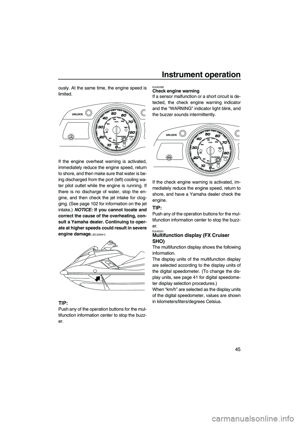
If the engine overheat warning is activated,
immediately reduce the engine speed, return
to shore, and then make sure that water is be-
ing discharged from the port (left) cooling wa-
ter pilot outlet while the engine is running. If
there is no discharge of water, stop the en-
gine, and then check the jet intake for clog-
ging. (See page 102 for information on the jet
intake.) NOTICE: If you cannot locate and
correct the cause of the overheating, con-
sult a Yamaha dealer. Continuing to oper-
ate at higher speeds could result in severe
engine damage.
[ECJ00041]
TIP:
Push any of the operation buttons for the mul-
tifunction information center to stop the buzz-
er.
EJU42280Check engine warning
If a sensor malfunction or a short circuit is de-
tected, the check engine warning indicator
and the “WARNING” indicator light blink, and
the buzzer sounds intermittently.
If the check engine warning is activated, im-
mediately reduce the engine speed, return to
shore, and have a Yamaha dealer check the
engine.
TIP:
Push any of the operation buttons for the mul-
tifunction information center to stop the buzz-
er.
EJU42251Multifunction display (FX Cruiser
SHO)
The multifunction display shows the following
information.
The display units of the multifunction display
are selected according to the display units of
the digital speedometer. (To change the dis-
play units, see page 41 for digital speedome-
ter display selection procedures.)
When “km/h” are selected as the display units
of the digital speedometer, values are shown
in kilometers/liters/degrees Celsius.
UF2S71E0.book Page 45 Tuesday, August 21, 2012 2:33 PM
Page 52 of 116
Instrument operation
46
When “mph” are selected as the display units
of the digital speedometer, values are shown
in miles/gallons/degrees Fahrenheit.
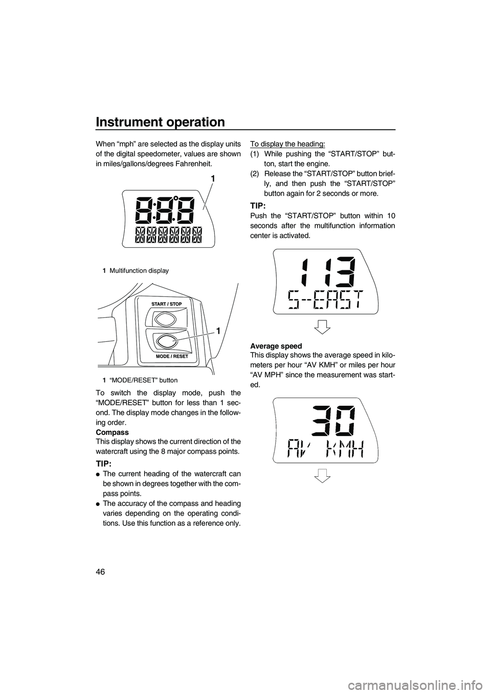
To switch the display mode, push the
“MODE/RESET” button for less than 1 sec-
ond. The display mode changes in the follow-
ing order.
Compass
This display shows the current direction of the
watercraft using the 8 major compass points.
TIP:
●The current heading of the watercraft can
be shown in degrees together with the com-
pass points.
●The accuracy of the compass and heading
varies depending on the operating condi-
tions. Use this function as a reference only.To display the heading:
(1) While pushing the “START/STOP” but-
ton, start the engine.
(2) Release the “START/STOP” button brief- ly, and then push the “START/STOP”
button again for 2 seconds or more.
TIP:
Push the “START/STOP” button within 10
seconds after the multifunction information
center is activated.
Average speed
This display shows the average speed in kilo-
meters per hour “AV KMH” or miles per hour
“AV MPH” since the measurement was start-
ed.
1Multifunction display
1 “MODE/RESET” button
1
1
UF2S71E0.book Page 46 Tuesday, August 21, 2012 2:33 PM
Page 53 of 116
Instrument operation
47
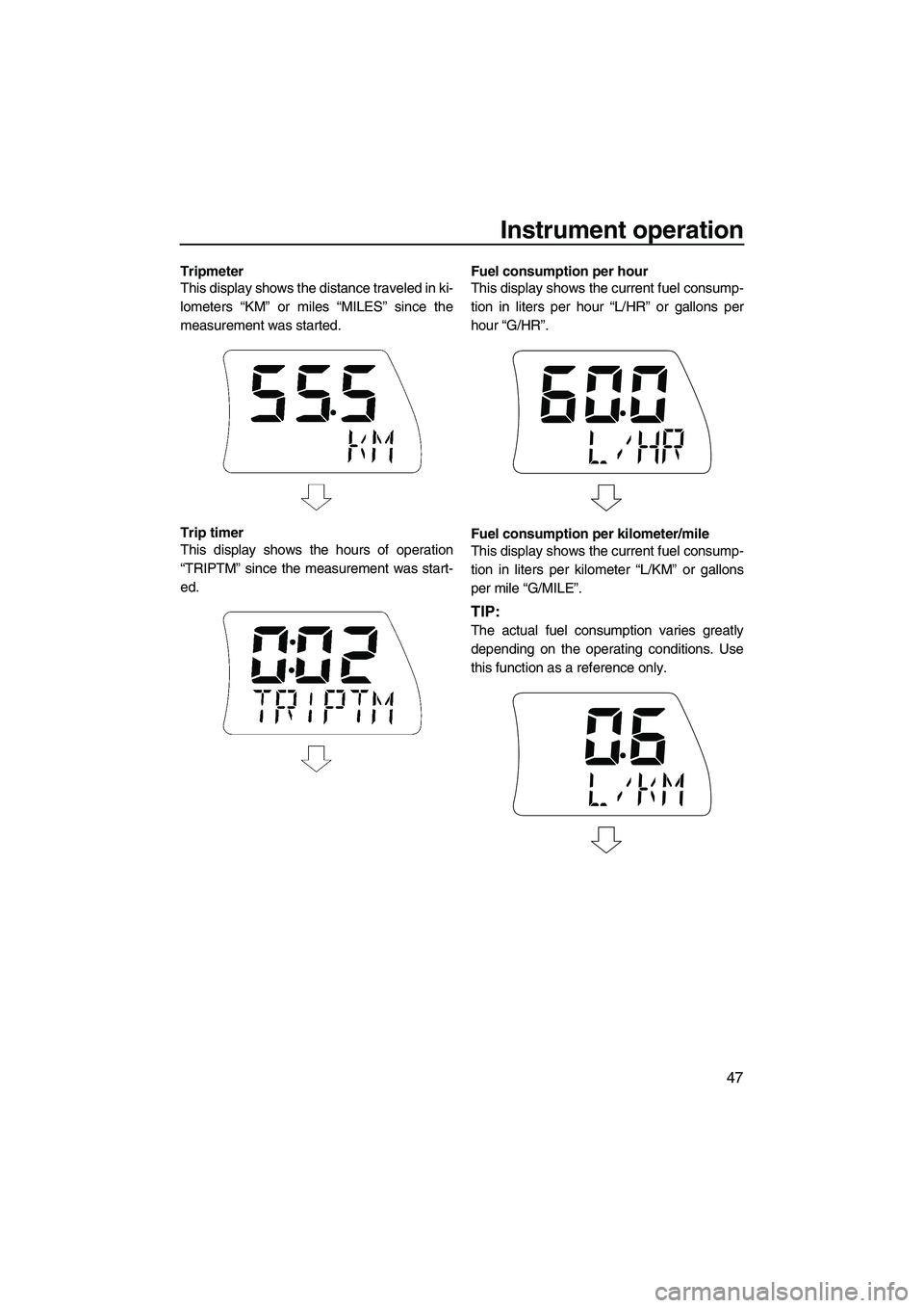
Tripmeter
This display shows the distance traveled in ki-
lometers “KM” or miles “MILES” since the
measurement was started.
Trip timer
This display shows the hours of operation
“TRIPTM” since the measurement was start-
ed.Fuel consumption per hour
This display shows the current fuel consump-
tion in liters per hour “L/HR” or gallons per
hour “G/HR”.
Fuel consumption per kilometer/mile
This display shows the current fuel consump-
tion in liters per kilometer “L/KM” or gallons
per mile “G/MILE”.
TIP:
The actual fuel consumption varies greatly
depending on the operating conditions. Use
this function as a reference only.
UF2S71E0.book Page 47 Tuesday, August 21, 2012 2:33 PM
Page 54 of 116
Instrument operation
48
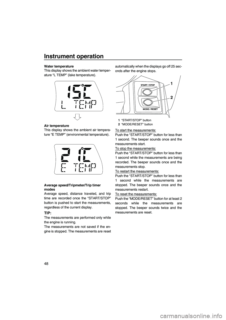
Water temperature
This display shows the ambient water temper-
ature “L TEMP” (lake temperature).
Air temperature
This display shows the ambient air tempera-
ture “E TEMP” (environmental temperature).
Average speed/Tripmeter/Trip timer
modes
Average speed, distance traveled, and trip
time are recorded once the “START/STOP”
button is pushed to start the measurements,
regardless of the current display.
TIP:
The measurements are performed only while
the engine is running.
The measurements are not saved if the en-
gine is stopped. The measurements are resetautomatically when the displays go off 25 sec-
onds after the engine stops.
To start the measurements:
Push the “START/STOP” button for less than
1 second. The beeper sounds once and the
measurements start.
To stop the measurements:
Push the “START/STOP” button for less than
1 second while the measurements are being
recorded. The beeper sounds once and the
measurements stop.
To restart the measurements:
Push the “START/STOP” button for less than
1 second while the measurements are
stopped. The beeper sounds once and the
measurements restart.
To reset the measurements:
Push the “MODE/RESET” button for at least 2
seconds while the measurements are
stopped. The beeper sounds twice and the
measurements are reset.
1
“START/STOP” button
2 “MODE/RESET” button
1
2
UF2S71E0.book Page 48 Tuesday, August 21, 2012 2:33 PM
Page 55 of 116
Equipment operation
49
EJU40333
Equipment EJU42202Seats
The front and rear seats are removable.
Remove the seats to access the engine com-
partment and removable watertight storage
compartment.
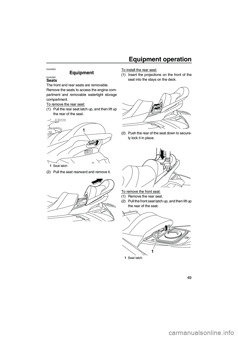
To remove the rear seat:
(1) Pull the rear seat latch up, and then lift upthe rear of the seat.
(2) Pull the seat rearward and remove it. To install the rear seat:
(1) Insert the projections on the front of the
seat into the stays on the deck.
(2) Push the rear of the seat down to secure- ly lock it in place.
To remove the front seat:
(1) Remove the rear seat.
(2) Pull the front seat latch up, and then lift up the rear of the seat.
1Seat latch
1
1Seat latch
1
UF2S71E0.book Page 49 Tuesday, August 21, 2012 2:33 PM
Page 56 of 116
Equipment operation
50
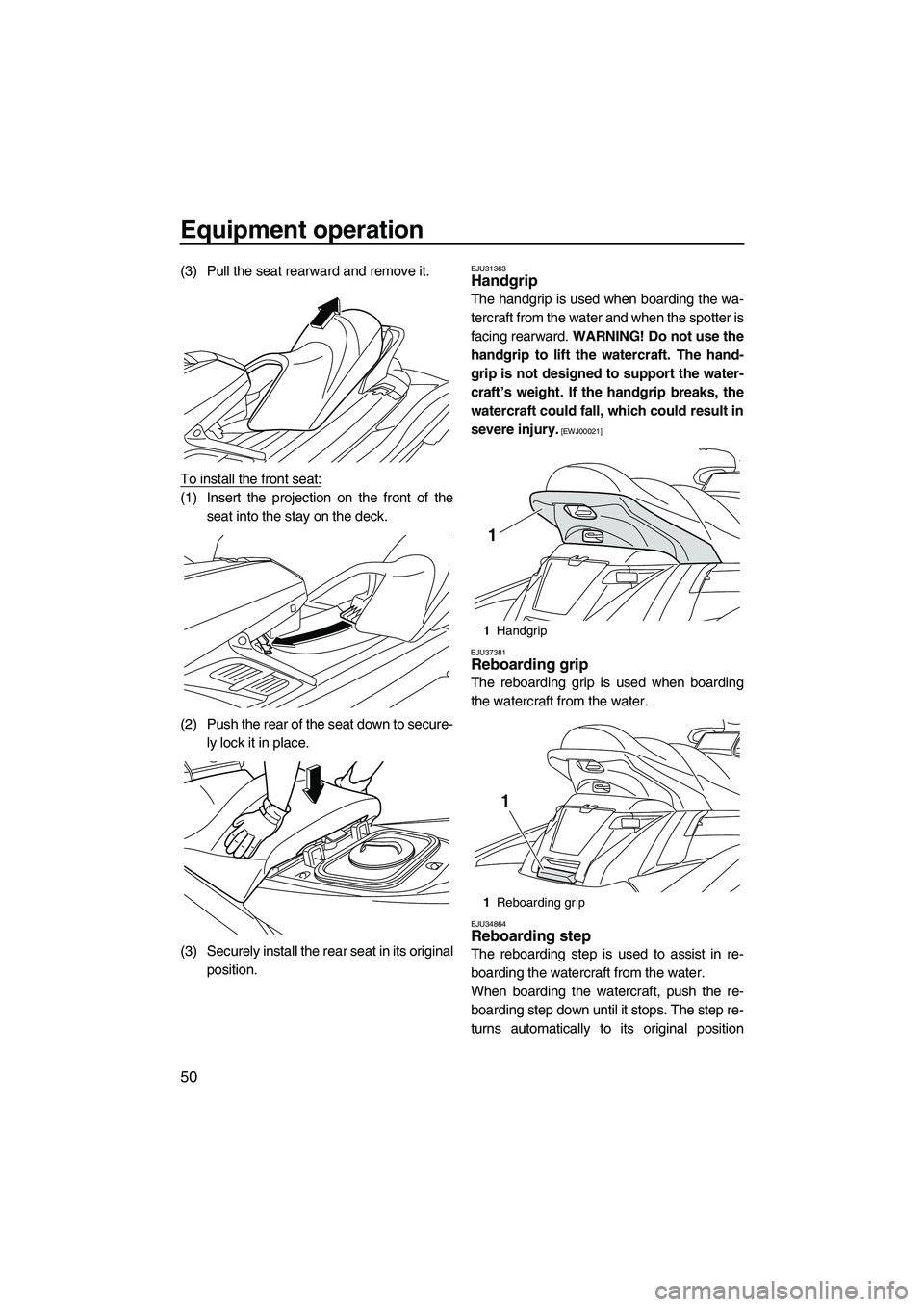
(3) Pull the seat rearward and remove it.
To install the front seat:
(1) Insert the projection on the front of theseat into the stay on the deck.
(2) Push the rear of the seat down to secure- ly lock it in place.
(3) Securely install the rear seat in its original position.
EJU31363Handgrip
The handgrip is used when boarding the wa-
tercraft from the water and when the spotter is
facing rearward. WARNING! Do not use the
handgrip to lift the watercraft. The hand-
grip is not designed to support the water-
craft’s weight. If the handgrip breaks, the
watercraft could fall, which could result in
severe injury.
[EWJ00021]
EJU37381
Reboarding grip
The reboarding grip is used when boarding
the watercraft from the water.
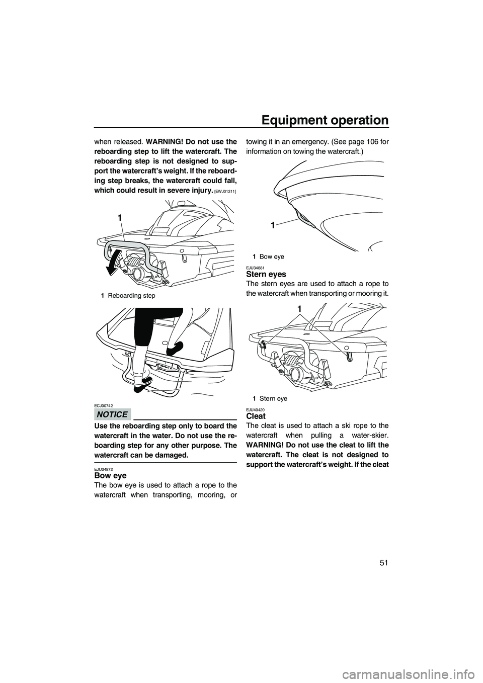
EJU34864Reboarding step
The reboarding step is used to assist in re-
boarding the watercraft from the water.
When boarding the watercraft, push the re-
boarding step down until it stops. The step re-
turns automatically to its original position
1 Handgrip
1 Reboarding grip
1
1
UF2S71E0.book Page 50 Tuesday, August 21, 2012 2:33 PM
Page 57 of 116
Equipment operation
51
when released. WARNING! Do not use the
reboarding step to lift the watercraft. The
reboarding step is not designed to sup-
port the watercraft’s weight. If the reboard-
ing step breaks, the watercraft could fall,
which could result in severe injury.
[EWJ01211]
NOTICE
ECJ00742
Use the reboarding step only to board the
watercraft in the water. Do not use the re-
boarding step for any other purpose. The
watercraft can be damaged.
EJU34872Bow eye
The bow eye is used to attach a rope to the
watercraft when transporting, mooring, or towing it in an emergency. (See page 106 for
information on towing the watercraft.)
EJU34881Stern eyes
The stern eyes are used to attach a rope to
the watercraft when transporting or mooring it.
EJU40420Cleat
The cleat is used to attach a ski rope to the
watercraft when pulling a water-skier.
WARNING! Do not use the cleat to lift the watercraft. The cleat is not designed to
support the watercraft’s weight. If the cleat
1 Reboarding step
1
1Bow eye
1 Stern eye
1
1
UF2S71E0.book Page 51 Tuesday, August 21, 2012 2:33 PM
Page 58 of 116
![YAMAHA FX HO CRUISER 2013 Workshop Manual Equipment operation
52
breaks, the watercraft could fall, which
could result in severe injury.
[EWJ01510]
EJU34892
Pull-up cleats (FX Cruiser SHO)
The pull-up cleats are used to attach a rope to
the YAMAHA FX HO CRUISER 2013 Workshop Manual Equipment operation
52
breaks, the watercraft could fall, which
could result in severe injury.
[EWJ01510]
EJU34892
Pull-up cleats (FX Cruiser SHO)
The pull-up cleats are used to attach a rope to
the](/img/51/49770/w960_49770-57.png)
Equipment operation
52
breaks, the watercraft could fall, which
could result in severe injury.
[EWJ01510]
EJU34892
Pull-up cleats (FX Cruiser SHO)
The pull-up cleats are used to attach a rope to
the watercraft when mooring it.
To use a pull-up cleat, pull it up. The pull-up
cleat returns automatically to its original posi-
tion when released. WARNING! Do not use
the pull-up cleats to lift the watercraft. The
pull-up cleats are not designed to support
the watercraft’s weight. If the pull-up
cleats break, the watercraft could fall,
which could result in severe injury.
[EWJ00821]
EJU42290
Storage compartments
This watercraft is equipped with the following
storage compartments.
Only the securely closed watertight storage
compartments are waterproof. If you carry ob- jects that must be kept dry, put them in a wa-
terproof bag.
Make sure that the storage compartments are
closed securely before operating the water-
craft.
EJU42210Bow storage compartment
The bow storage compartment is located un-
der the hood.
To open the bow storage compartment:
Pull the hood latch rearward, and then lift up
the rear of the hood.
1
Cleat
1 Pull-up cleat
1
1
1Hood latch
1 Bow storage compartment
Bow storage compartment:
Capacity: 90.0 L (23.8 US gal, 19.8 Imp.gal)
Load limit:
5.0 kg (11 lb)
1
1
UF2S71E0.book Page 52 Tuesday, August 21, 2012 2:33 PM
Page 59 of 116
Equipment operation
53
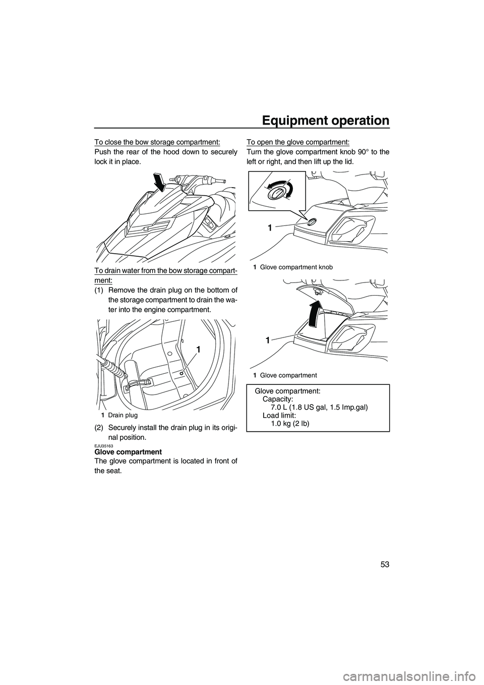
To close the bow storage compartment:
Push the rear of the hood down to securely
lock it in place.
To drain water from the bow storage compart-
ment:
(1) Remove the drain plug on the bottom ofthe storage compartment to drain the wa-
ter into the engine compartment.
(2) Securely install the drain plug in its origi- nal position.
EJU35163Glove compartment
The glove compartment is located in front of
the seat. To open the glove compartment:
Turn the glove compartment knob 90° to the
left or right, and then lift up the lid.
1
Drain plug
1
1Glove compartment knob
1 Glove compartment
Glove compartment:
Capacity: 7.0 L (1.8 US gal, 1.5 Imp.gal)
Load limit: 1.0 kg (2 lb)
1
1
UF2S71E0.book Page 53 Tuesday, August 21, 2012 2:33 PM
Page 60 of 116
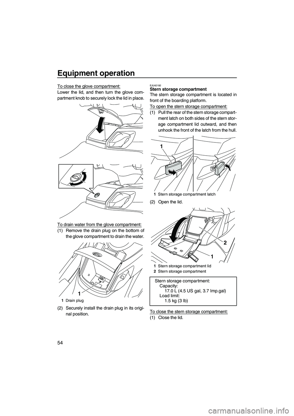
Equipment operation
54
To close the glove compartment:
Lower the lid, and then turn the glove com-
partment knob to securely lock the lid in place.
To drain water from the glove compartment:
(1) Remove the drain plug on the bottom ofthe glove compartment to drain the water.
(2) Securely install the drain plug in its origi- nal position.
EJU42192Stern storage compartment
The stern storage compartment is located in
front of the boarding platform.
To open the stern storage compartment:
(1) Pull the rear of the stern storage compart-ment latch on both sides of the stern stor-
age compartment lid outward, and then
unhook the front of the latch from the hull.
(2) Open the lid.
To close the stern storage compartment:
(1) Close the lid.
1 Drain plug
1
1Stern storage compartment latch
1 Stern storage compartment lid
2 Stern storage compartment
Stern storage compartment:
Capacity:
17.0 L (4.5 US gal, 3.7 Imp.gal)
Load limit: 1.5 kg (3 lb)
1
2
1
UF2S71E0.book Page 54 Tuesday, August 21, 2012 2:33 PM