warning YAMAHA FX HO CRUISER 2020 Owners Manual
[x] Cancel search | Manufacturer: YAMAHA, Model Year: 2020, Model line: FX HO CRUISER, Model: YAMAHA FX HO CRUISER 2020Pages: 116, PDF Size: 12.71 MB
Page 4 of 116
Important manual information
EJU30193
To the owner/operator
Thank you for choosing a Yamaha watercraft.
This owner’s/operator’s manual contains in-
formation you will need for proper operation,
maintenance, and care. If you have any ques-
tions about the operation or maintenance of
your watercraft, please consult a Yamaha
dealer.
This manual is not a course on boating safety
or seamanship. If this is your first watercraft,
or if you are changing to a type of watercraft
you are not familiar with, for your own com-
fort and safety, please ensure that you obtain
proper training or practice before operating
the watercraft by yourself. In addition, a
Yamaha dealer or boating organization will be
pleased to recommend local sea schools, or
competent instructors.
In this manual, information of particular im-
portance is distinguished in the following
ways:
This is the safety alert symbol. It is used
to alert you to potential personal injury haz-
ards. Obey all safety messages that follow
this symbol to avoid possible injury or death.
WARNING
EWJ00072
A WARNING indicates a hazardous situa-
tion which, if not avoided, could result in
death or serious injury.
NOTICE
ECJ00092
A NOTICE indicates special precautions
that must be taken to avoid damage to the
watercraft or other property.
TIP:
A TIP provides key information to make pro-
cedures easier or clearer.
EJU45451
Engine data recording
This model’s ECM stores certain engine data
to assist in the diagnosis of malfunctions and
for research, statistical analysis and develop-
ment purposes.
Although the sensors and recorded data will
vary by model, the main data points are:
Engine status and engine performance
data
This data will be uploaded only when a spe-
cial Yamaha diagnostic tool is attached to the
engine, such as when maintenance checks or
service procedures are performed. Engine
data uploaded will be handled appropriately
according to the following Privacy Policy.
Privacy Policy
Yamaha will not disclose this data to a third
party except in the following cases. In addi-
tion, Yamaha may provide engine data to a
contractor in order to outsource services re-
lated to the handling of the engine data. Even
in this case, Yamaha will require the contrac-
tor to properly handle the engine data we
provided and Yamaha will appropriately
manage the data.
With the consent of the boat owner
Where obligated by law
For use by Yamaha in litigation
For general Yamaha-conducted research
purposes when the data is not related to an
individual engine or owner
https://www.yamaha-motor.eu/eu/
privacy/privacy-policy.aspx
UF3V71E0.book Page 2 Tuesday, June 25, 2019 9:14 AM
Page 6 of 116

Table of contents
General and important labels ........... 1
Identification numbers .................... 1
Primary Identification (PRI-ID)
number............................................ 1
Craft Identification Number (CIN) ....... 1
Engine serial number.......................... 1
Manufactured date label .................... 2
Model information ........................... 2
Builder’s plate .................................... 2
Important labels .............................. 4
Warning labels.................................... 5
Other labels ........................................ 8
Safety information ........................... 10
Limitations on who may operate
the watercraft ............................. 10
Cruising limitations ........................ 11
Operation requirements ................ 12
Recommended equipment ........... 14
Hazard information........................ 15
Watercraft characteristics ............. 15
Wakeboarding and water-skiing ... 17
Safe boating rules ......................... 18
Enjoy your watercraft
responsibly ................................. 19
Description....................................... 20
Watercraft glossary ....................... 20
Location of main components ...... 21
Control function operation ............. 25
Watercraft control functions ......... 25
Yamaha Security System ................. 25
Engine stop switch .......................... 26
Engine shut-off switch .................... 26
Start switch ..................................... 26
Throttle lever .................................... 27
RiDE lever ........................................ 27
Steering system ............................... 27
Adjustable tilt steering system ......... 28
Cooling water pilot outlet ................. 29
Water separator................................ 29
Watercraft operation ...................... 30
Watercraft operation functions ..... 30
Shift system ..................................... 30
Electric trim system .......................... 32
Watercraft operation modes ......... 34
Reverse assist .................................. 34
T.D.E.
(thrust directional enhancer) ......... 34
No-wake mode ................................. 35
Drive control mode ........................... 36
Cruise assist ..................................... 38
Instrument operation ...................... 40
Multifunction information center ... 40
Operation buttons ............................ 41
Touch screen.................................... 41
Status area ....................................... 42
Home screen ................................... 42
Information screen .......................... 43
Drive control mode screen .............. 44
Setting menu screen ....................... 44
Engine lock screen .......................... 46
Warning function .............................. 46
Equipment operation ...................... 49
Equipment..................................... 49
Seats ................................................ 49
Handgrip........................................... 50
Reboarding grip................................ 50
Reboarding step ............................... 50
Bow eye............................................ 51
Stern eyes ........................................ 51
Cleat ................................................. 51
Pull-up cleats (FX Cruiser HO).......... 52
Storage compartments .................... 52
Fire extinguisher holder and cover ... 55
Optional part mounting bracket ....... 56
Operation and handling
requirements ................................... 57
Fuel requirements ......................... 57
Fuel................................................... 57
Engine oil requirements ................ 59
Engine oil .......................................... 59
UF3V71E0.book Page 1 Tuesday, June 25, 2019 9:14 AM
Page 12 of 116

General and important labels
5
EJU35914Warning labels
If any of these labels are damaged or missing, contact a Yamaha dealer for replacements.
1
UF3V71E0.book Page 5 Tuesday, June 25, 2019 9:14 AM
Page 35 of 116
Control function operation
28
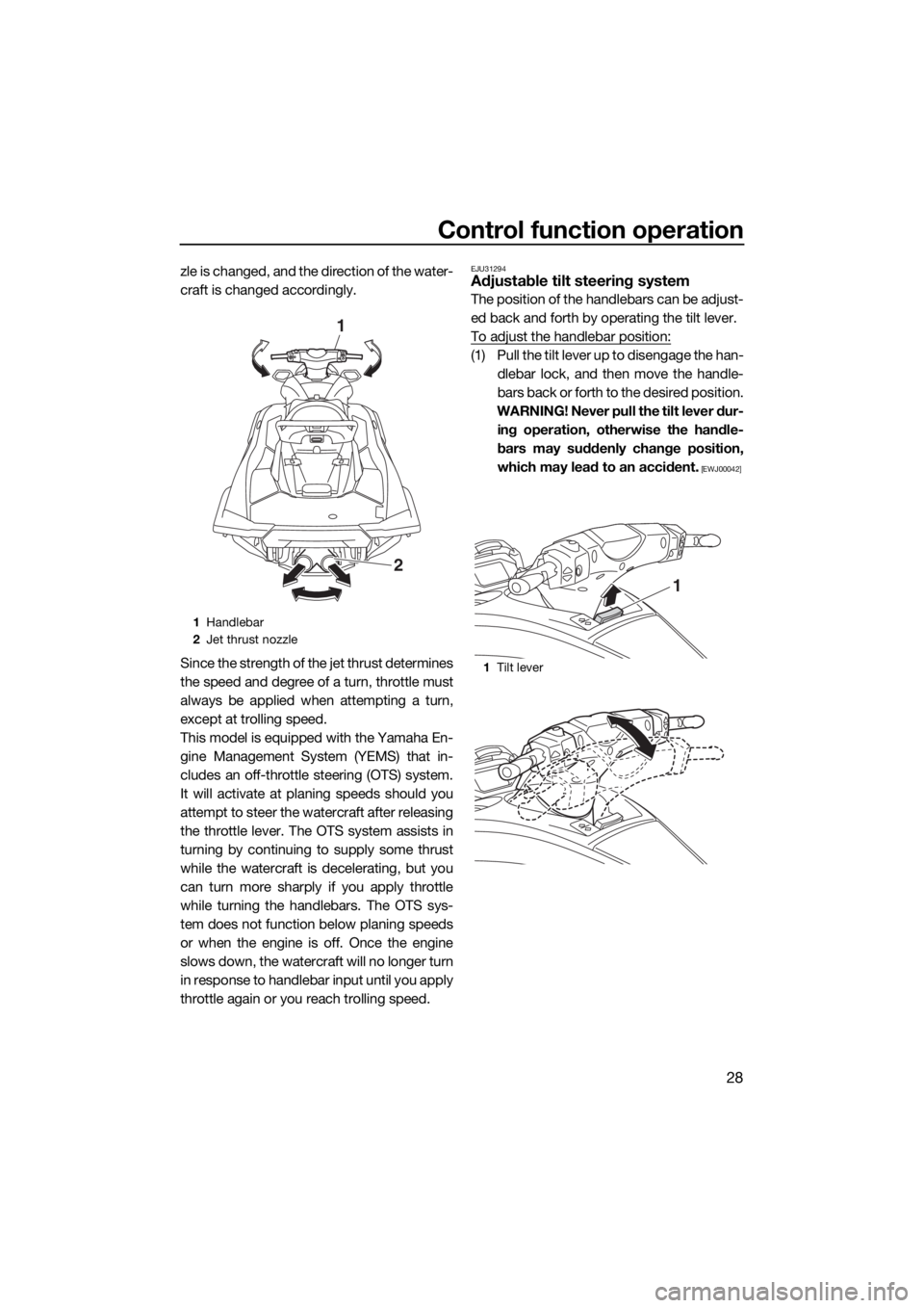
zle is changed, and the direction of the water-
craft is changed accordingly.
Since the strength of the jet thrust determines
the speed and degree of a turn, throttle must
always be applied when attempting a turn,
except at trolling speed.
This model is equipped with the Yamaha En-
gine Management System (YEMS) that in-
cludes an off-throttle steering (OTS) system.
It will activate at planing speeds should you
attempt to steer the watercraft after releasing
the throttle lever. The OTS system assists in
turning by continuing to supply some thrust
while the watercraft is decelerating, but you
can turn more sharply if you apply throttle
while turning the handlebars. The OTS sys-
tem does not function below planing speeds
or when the engine is off. Once the engine
slows down, the watercraft will no longer turn
in response to handlebar input until you apply
throttle again or you reach trolling speed.EJU31294Adjustable tilt steering system
The position of the handlebars can be adjust-
ed back and forth by operating the tilt lever.
To adjust the handlebar position:
(1) Pull the tilt lever up to disengage the han-
dlebar lock, and then move the handle-
bars back or forth to the desired position.
WARNING! Never pull the tilt lever dur-
ing operation, otherwise the handle-
bars may suddenly change position,
which may lead to an accident.
[EWJ00042]
1Handlebar
2Jet thrust nozzle
1
2
1Tilt lever
1
UF3V71E0.book Page 28 Tuesday, June 25, 2019 9:14 AM
Page 37 of 116
Watercraft operation
30
EJU40014
Watercraft operation functions
EJU43154Shift system
WARNING
EWJ01773
Make sure that there are no obstacles or
people behind you before shifting into
reverse.
Do not touch the reverse gate while the
RiDE lever is being operated, otherwise
you could be pinched.
If the RiDE lever and throttle lever are
being operated at the same time, do not
release only the RiDE lever. Otherwise,
the watercraft could accelerate more
quickly than expected, which may lead
to an accident.
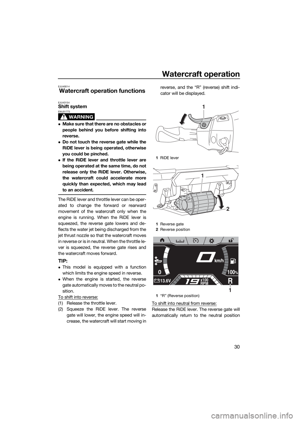
The RiDE lever and throttle lever can be oper-
ated to change the forward or rearward
movement of the watercraft only when the
engine is running. When the RiDE lever is
squeezed, the reverse gate lowers and de-
flects the water jet being discharged from the
jet thrust nozzle so that the watercraft moves
in reverse or is in neutral. When the throttle le-
ver is squeezed, the reverse gate rises and
the watercraft moves forward.
TIP:
This model is equipped with a function
which limits the engine speed in reverse.
When the engine is started, the reverse
gate automatically moves to the neutral po-
sition.
To shift into reverse:
(1) Release the throttle lever.
(2) Squeeze the RiDE lever. The reverse
gate will lower, the engine speed will in-
crease, the watercraft will start moving inreverse, and the “R” (reverse) shift indi-
cator will be displayed.
To shift into neutral from reverse:
Release the RiDE lever. The reverse gate will
automatically return to the neutral position
1RiDE lever
1Reverse gate
2Reverse position
1“R” (Reverse position)
1
2
1
0
R13.6Vx100
RPM
100%
km/h
1
UF3V71E0.book Page 30 Tuesday, June 25, 2019 9:14 AM
Page 47 of 116
Instrument operation
40
EJU45110
Multifunction information
center
The multifunction information center displays
various watercraft information.
The multifunction information center is a
touch screen that you can touch directly to
turn the various functions on or off or change
settings.
In addition, the language and display units
shown can be changed. (See page 44 for in-
formation on changing the language and dis-
play units.) In the illustrations in this manual,
English is used for the language and US units
are used for the display units.
WARNING
EWJ01980
For safety, do not touch the multifunction
information center while the watercraft is
moving. Otherwise, you could lose control
of the watercraft, which may lead to an ac-
cident.
TIP:
The multifunction information center does not
receive operation input while the watercraft is
moving. Before operating the multifunction
information center, stop the watercraft and
check the area around you to make sure it is
safe to operate the center.
Turning on the multifunction information
center
When the start switch is pushed, the multi-
function information center turns on. After the
logo display appears for a few seconds, the
home screen is displayed and the touch
screen can be operated by touching it.
TIP:
Perform one of the following operations to
turn on the multifunction information center
without starting the engine.
Push the start switch briefly.
While pushing the engine stop switch,
push the start switch.
Turning off the multifunction information
center
If the multifunction information center does
not receive any operation input within 25 sec-
onds after the engine stops or if 3 minutes
has elapsed after the engine stops, the center
turns off.
TIP:
The multifunction information center turns off
3 minutes after the engine stops even if there
is operation input.
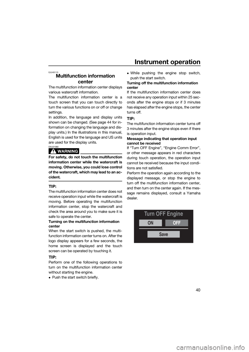
Message indicating that operation input
cannot be received
If “Turn OFF Engine”, “Engine Comm Error”,
or other message appears in red characters
during touch operation, the operation input
cannot be received because the input condi-
tions are not satisfied.
Perform the operation again according to the
displayed message, or stop the engine to
turn off the multifunction information center,
and then turn on the center again. If the mes-
sage remains displayed, consult a Yamaha
dealer.
ONOFF
Turn OFF Engine
Save
UF3V71E0.book Page 40 Tuesday, June 25, 2019 9:14 AM
Page 48 of 116
Instrument operation
41
EJU45121Operation buttons
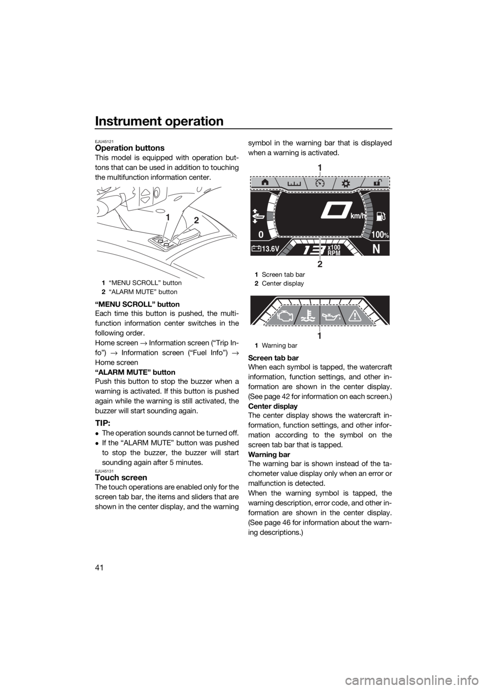
This model is equipped with operation but-
tons that can be used in addition to touching
the multifunction information center.
“MENU SCROLL” button
Each time this button is pushed, the multi-
function information center switches in the
following order.
Home screen → Information screen (“Trip In-
fo”) → Information screen (“Fuel Info”) →
Home screen
“ALARM MUTE” button
Push this button to stop the buzzer when a
warning is activated. If this button is pushed
again while the warning is still activated, the
buzzer will start sounding again.
TIP:
The operation sounds cannot be turned off.
If the “ALARM MUTE” button was pushed
to stop the buzzer, the buzzer will start
sounding again after 5 minutes.
EJU45131Touch screen
The touch operations are enabled only for the
screen tab bar, the items and sliders that are
shown in the center display, and the warningsymbol in the warning bar that is displayed
when a warning is activated.
Screen tab bar
When each symbol is tapped, the watercraft
information, function settings, and other in-
formation are shown in the center display.
(See page 42 for information on each screen.)
Center display
The center display shows the watercraft in-
formation, function settings, and other infor-
mation according to the symbol on the
screen tab bar that is tapped.
Warning bar
The warning bar is shown instead of the ta-
chometer value display only when an error or
malfunction is detected.
When the warning symbol is tapped, the
warning description, error code, and other in-
formation are shown in the center display.
(See page 46 for information about the warn-
ing descriptions.)
1“MENU SCROLL” button
2“ALARM MUTE” button
12
1Screen tab bar
2Center display
1Warning bar
0
N13.6Vx100
RPM
100%
km/h
1
2
1
UF3V71E0.book Page 41 Tuesday, June 25, 2019 9:14 AM
Page 49 of 116
Instrument operation
42
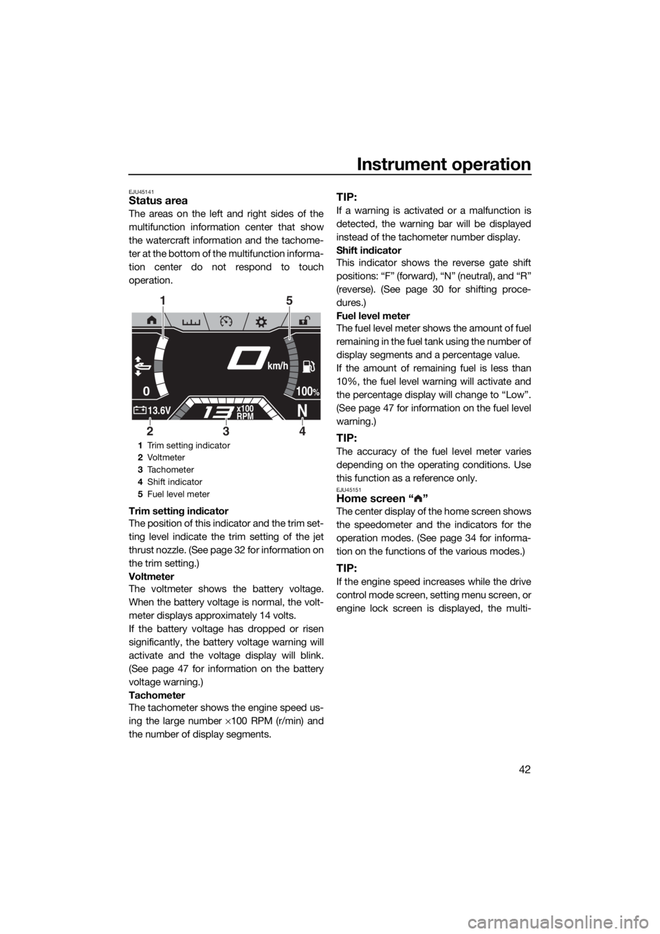
EJU45141Status area
The areas on the left and right sides of the
multifunction information center that show
the watercraft information and the tachome-
ter at the bottom of the multifunction informa-
tion center do not respond to touch
operation.
Trim setting indicator
The position of this indicator and the trim set-
ting level indicate the trim setting of the jet
thrust nozzle. (See page 32 for information on
the trim setting.)
Voltmeter
The voltmeter shows the battery voltage.
When the battery voltage is normal, the volt-
meter displays approximately 14 volts.
If the battery voltage has dropped or risen
significantly, the battery voltage warning will
activate and the voltage display will blink.
(See page 47 for information on the battery
voltage warning.)
Tachometer
The tachometer shows the engine speed us-
ing the large number ×100 RPM (r/min) and
the number of display segments.
TIP:
If a warning is activated or a malfunction is
detected, the warning bar will be displayed
instead of the tachometer number display.
Shift indicator
This indicator shows the reverse gate shift
positions: “F” (forward), “N” (neutral), and “R”
(reverse). (See page 30 for shifting proce-
dures.)
Fuel level meter
The fuel level meter shows the amount of fuel
remaining in the fuel tank using the number of
display segments and a percentage value.
If the amount of remaining fuel is less than
10%, the fuel level warning will activate and
the percentage display will change to “Low”.
(See page 47 for information on the fuel level
warning.)
TIP:
The accuracy of the fuel level meter varies
depending on the operating conditions. Use
this function as a reference only.
EJU45151Home screen “ ”
The center display of the home screen shows
the speedometer and the indicators for the
operation modes. (See page 34 for informa-
tion on the functions of the various modes.)
TIP:
If the engine speed increases while the drive
control mode screen, setting menu screen, or
engine lock screen is displayed, the multi-
1Trim setting indicator
2Vo l t m et e r
3Tachometer
4Shift indicator
5Fuel level meter
0
N13.6Vx100
RPM
100%
km/h
15
423
UF3V71E0.book Page 42 Tuesday, June 25, 2019 9:14 AM
Page 53 of 116
Instrument operation
46
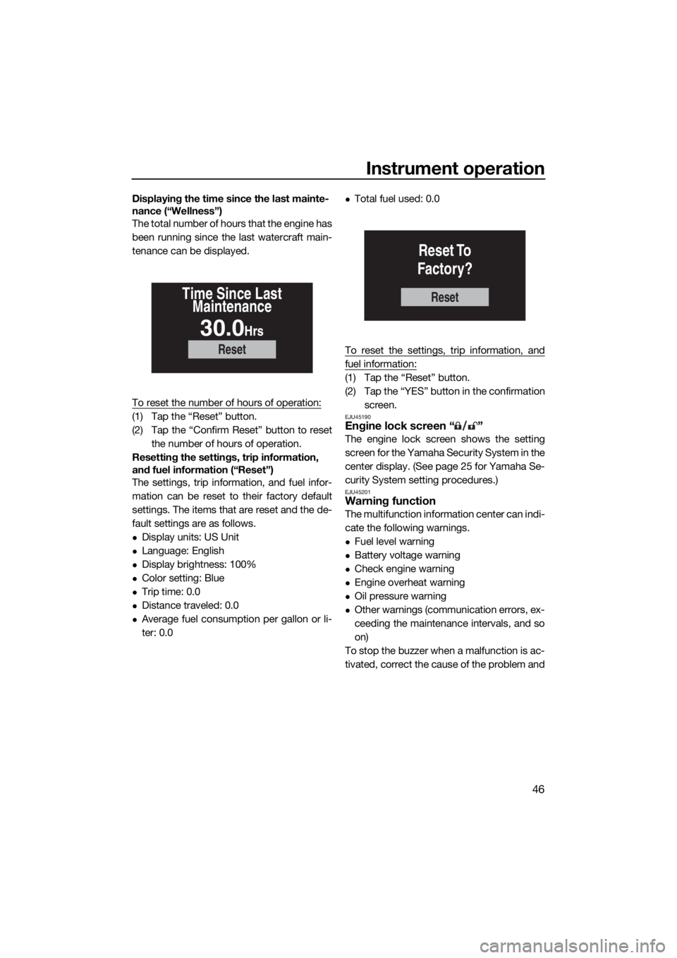
Displaying the time since the last mainte-
nance (“Wellness”)
The total number of hours that the engine has
been running since the last watercraft main-
tenance can be displayed.
To reset the number of hours of operation:
(1) Tap the “Reset” button.
(2) Tap the “Confirm Reset” button to reset
the number of hours of operation.
Resetting the settings, trip information,
and fuel information (“Reset”)
The settings, trip information, and fuel infor-
mation can be reset to their factory default
settings. The items that are reset and the de-
fault settings are as follows.
Display units: US Unit
Language: English
Display brightness: 100%
Color setting: Blue
Trip time: 0.0
Distance traveled: 0.0
Average fuel consumption per gallon or li-
ter: 0.0
Total fuel used: 0.0
To reset the settings, trip information, and
fuel information:
(1) Tap the “Reset” button.
(2) Tap the “YES” button in the confirmation
screen.
EJU45190Engine lock screen “ ”
The engine lock screen shows the setting
screen for the Yamaha Security System in the
center display. (See page 25 for Yamaha Se-
curity System setting procedures.)
EJU45201Warning function
The multifunction information center can indi-
cate the following warnings.
Fuel level warning
Battery voltage warning
Check engine warning
Engine overheat warning
Oil pressure warning
Other warnings (communication errors, ex-
ceeding the maintenance intervals, and so
on)
To stop the buzzer when a malfunction is ac-
tivated, correct the cause of the problem and
Reset
Time Since Last
Maintenance
30.0Hrs
Reset
Reset To
Factory?
UF3V71E0.book Page 46 Tuesday, June 25, 2019 9:14 AM
Page 54 of 116
Instrument operation
47
start the engine again, or push the “ALARM
MUTE” button.
TIP:
If the “ALARM MUTE” button was pushed to
stop the buzzer, the buzzer will start sound-
ing again after 5 minutes.
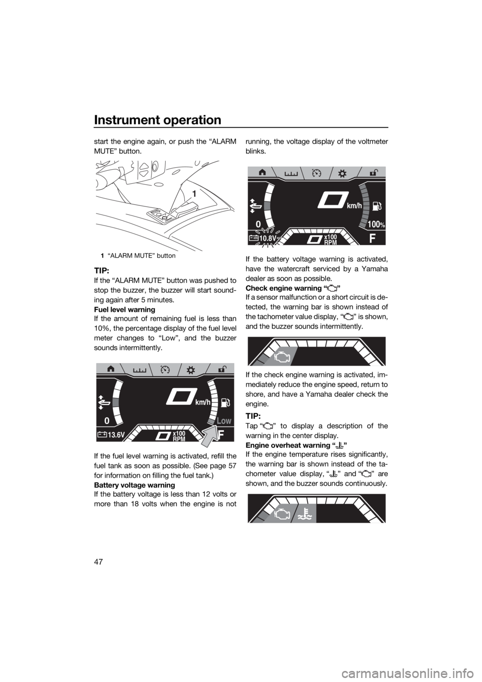
Fuel level warning
If the amount of remaining fuel is less than
10%, the percentage display of the fuel level
meter changes to “Low”, and the buzzer
sounds intermittently.
If the fuel level warning is activated, refill the
fuel tank as soon as possible. (See page 57
for information on filling the fuel tank.)
Battery voltage warning
If the battery voltage is less than 12 volts or
more than 18 volts when the engine is notrunning, the voltage display of the voltmeter
blinks.
If the battery voltage warning is activated,
have the watercraft serviced by a Yamaha
dealer as soon as possible.
Check engine warning “ ”
If a sensor malfunction or a short circuit is de-
tected, the warning bar is shown instead of
the tachometer value display, “ ” is shown,
and the buzzer sounds intermittently.
If the check engine warning is activated, im-
mediately reduce the engine speed, return to
shore, and have a Yamaha dealer check the
engine.
TIP:
Tap “ ” to display a description of the
warning in the center display.
Engine overheat warning “ ”
If the engine temperature rises significantly,
the warning bar is shown instead of the ta-
chometer value display, “ ” and “ ” are
shown, and the buzzer sounds continuously.
1“ALARM MUTE” button
1
Low0
F13.6Vx100
RPM
km/h
0
F10.8Vx100
RPM
100%
km/h
UF3V71E0.book Page 47 Tuesday, June 25, 2019 9:14 AM