remove seats YAMAHA FX SVHO 2021 Owners Manual
[x] Cancel search | Manufacturer: YAMAHA, Model Year: 2021, Model line: FX SVHO, Model: YAMAHA FX SVHO 2021Pages: 116, PDF Size: 5.03 MB
Page 56 of 116
Equipment operation
49
EJU40335
EquipmentEJU45210Seats
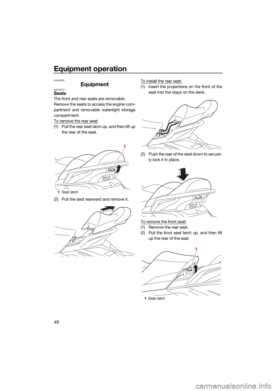
The front and rear seats are removable.
Remove the seats to access the engine com-
partment and removable watertight storage
compartment.
To remove the rear seat:
(1) Pull the rear seat latch up, and then lift upthe rear of the seat.
(2) Pull the seat rearward and remove it. To install the rear seat:
(1) Insert the projections on the front of the
seat into the stays on the deck.
(2) Push the rear of the seat down to secure- ly lock it in place.
To remove the front seat:
(1) Remove the rear seat.
(2) Pull the front seat latch up, and then lift up the rear of the seat.
1Seat latch
1
1Seat latch
1
UF3X72E0.book Page 49 Friday, May 29, 2020 10:09 AM
Page 65 of 116
Operation and handling requirements
58
To fill the fuel tank:
(1) Before refueling, stop the engine. Do notstand or sit on the watercraft. Never refu-
el while smoking, or while in the vicinity
of sparks, open flames, or other sources
of ignition.
(2) Place the watercraft in a well-ventilated area and in a horizontal position.
(3) Remove the seats, and then check the fuel level. (See page 49 for seat removal
and installation procedures.)
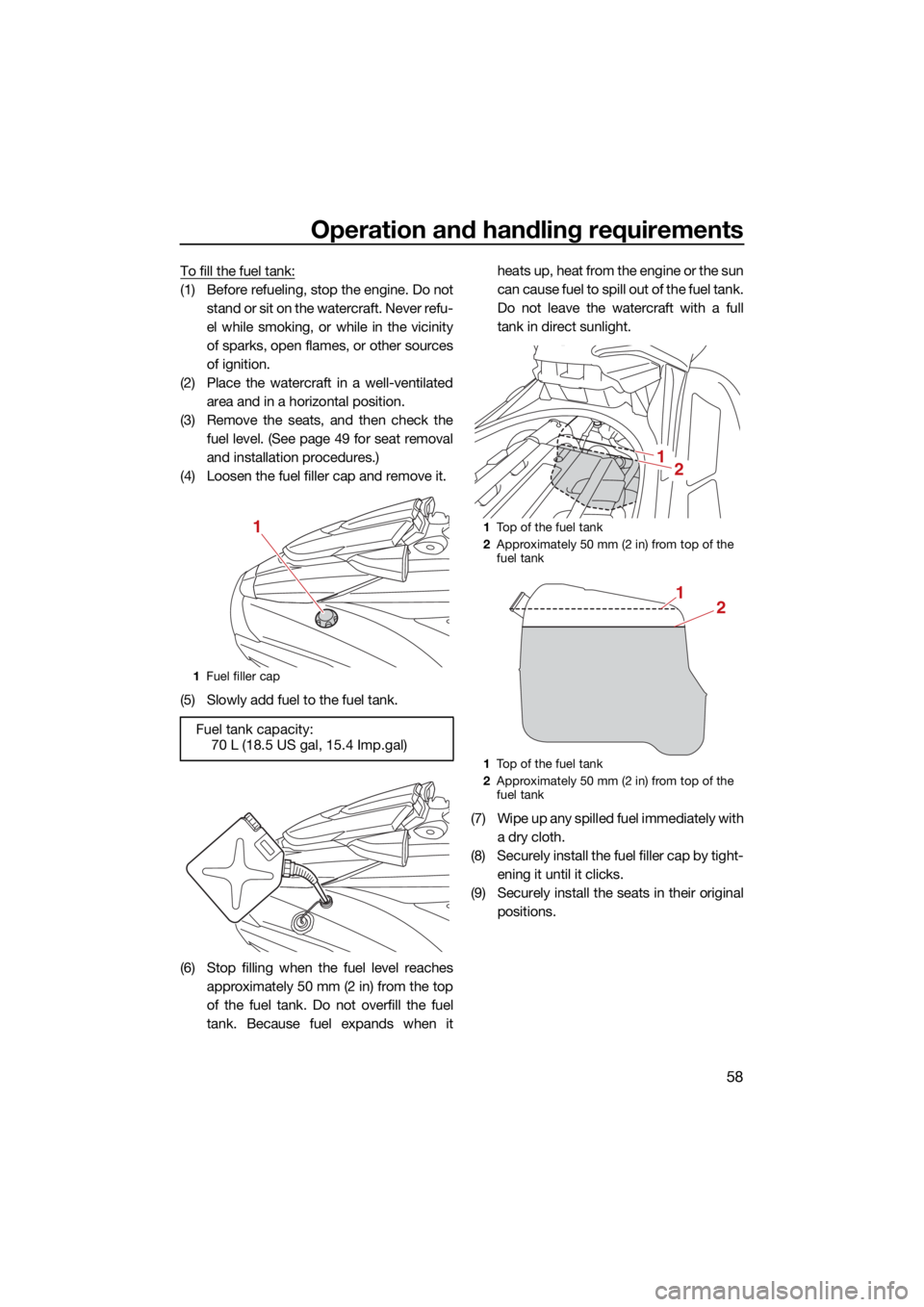
(4) Loosen the fuel filler cap and remove it.
(5) Slowly add fuel to the fuel tank.
(6) Stop filling when the fuel level reaches approximately 50 mm (2 in) from the top
of the fuel tank. Do not overfill the fuel
tank. Because fuel expands when it heats up, heat from the engine or the sun
can cause fuel to spill out of the fuel tank.
Do not leave the watercraft with a full
tank in direct sunlight.
(7) Wipe up any spilled fuel immediately with a dry cloth.
(8) Securely install the fuel filler cap by tight- ening it until it clicks.
(9) Securely install the seats in their original positions.
1Fuel filler cap
Fuel tank capacity:
70 L (18.5 US gal, 15.4 Imp.gal)
11Top of the fuel tank
2 Approximately 50 mm (2 in) from top of the
fuel tank
1 Top of the fuel tank
2 Approximately 50 mm (2 in) from top of the
fuel tank
21
21
UF3X72E0.book Page 58 Friday, May 29, 2020 10:09 AM
Page 66 of 116
Operation and handling requirements
59
EJU40291
Engine oil requirementsEJU41514Engine oilECJ00282
Use only 4-stroke engine oil. Usage of 2-
stroke engine oil could result in severe en-
gine damage.
TIP:
When the engine is operated at high speeds,
some engine oil may be consumed. Be sure
to check the engine oil level.
Why Yamalube
YAMALUBE oil is a Genuine YAMAHA Part
born of the engineers’ passion and belief that
engine oil is an important liquid engine com-
ponent. We form teams of specialists in the
fields of mechanical engineering, chemistry,
electronics and track testing, and have them
develop the engine together with the oil it will
use. Yamalube oils take full advantage of the
base oil’s qualities and blend in the ideal bal-
ance of additives to make sure the final oil
clears our performance standards. Thus,
Yamalube mineral, semisynthetic and syn- thetic oils have their own distinct characters
and value. Yamaha’s experience gained over
many years of research and development
into oil since the 1960’s helps make Yamalube the best choice for your Yamaha
engine.
Checking the engine oil level
EWJ00341
Engine oil is extremely hot immediately af-
ter the engine is turned off. Coming in con-
tact with or getting any engine oil on your
clothes could result in burns.
ECJ01002
Make sure that debris and water do not
enter the oil filler hole. Debris and water in
the engine oil can cause serious engine
damage.
To check the engine oil level:
(1) Place the watercraft in a precisely level position on land with the engine
stopped. If the engine was running, allow
the engine oil to settle by waiting 5 min-
utes or more before checking the oil lev-
el.
(2) Remove the seats. (See page 49 for seat removal and installation procedures.)
Recommended engine oil:
YAMALUBE 4W or 4-stroke motor oil
Recommended engine oil type: SAE 10W-30, 10W-40, 20W-40,
20W-50
Recommended engine oil grade: API SG, SH, SJ, SL
UF3X72E0.book Page 59 Friday, May 29, 2020 10:09 AM
Page 67 of 116
Operation and handling requirements
60
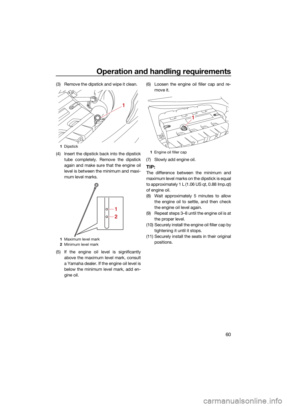
(3) Remove the dipstick and wipe it clean.
(4) Insert the dipstick back into the dipsticktube completely. Remove the dipstick
again and make sure that the engine oil
level is between the minimum and maxi-
mum level marks.
(5) If the engine oil level is significantly above the maximum level mark, consult
a Yamaha dealer. If the engine oil level is
below the minimum level mark, add en-
gine oil. (6) Loosen the engine oil filler cap and re-
move it.
(7) Slowly add engine oil.
TIP:
The difference between the minimum and
maximum level marks on the dipstick is equal
to approximately 1 L (1.06 US qt, 0.88 Imp.qt)
of engine oil.
(8) Wait approximately 5 minutes to allow the engine oil to settle, and then check
the engine oil level again.
(9) Repeat steps 3–8 until the engine oil is at the proper level.
(10) Securely install the engine oil filler cap by tightening it until it stops.
(11) Securely install the seats in their original positions.
1Dipstick
1 Maximum level mark
2 Minimum level mark
1
1
2
1Engine oil filler cap
1
UF3X72E0.book Page 60 Friday, May 29, 2020 10:09 AM
Page 73 of 116
Pre-operation checks
66
EJU32282
Pre-operation check pointsEJU42384Pre-launch checks
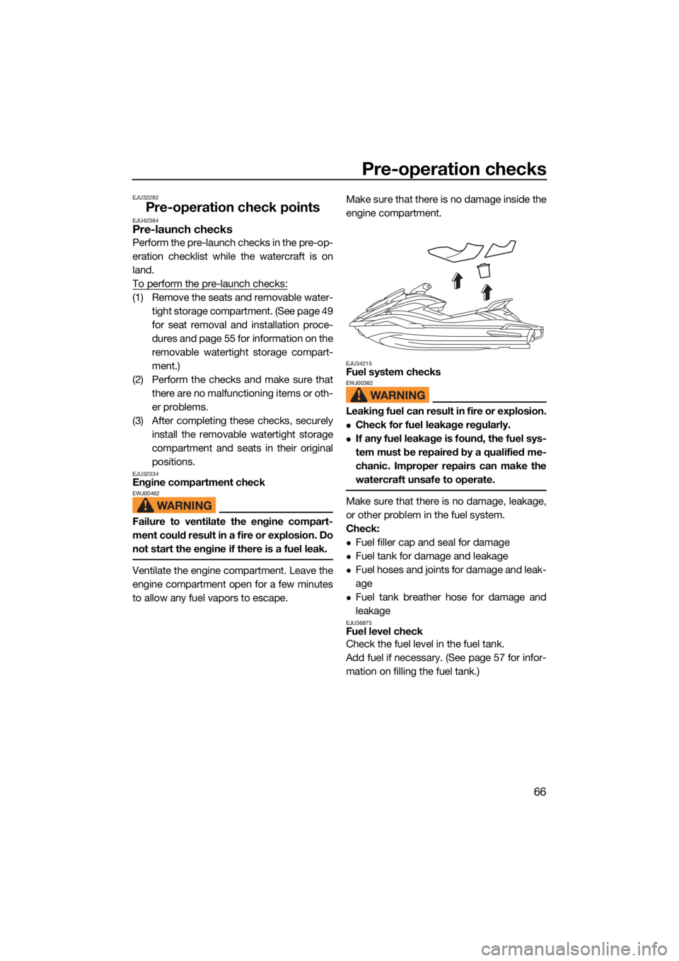
Perform the pre-launch checks in the pre-op-
eration checklist while the watercraft is on
land.
To perform the pre-launch checks:
(1) Remove the seats and removable water-tight storage compartment. (See page 49
for seat removal and installation proce-
dures and page 55 for information on the
removable watertight storage compart-
ment.)
(2) Perform the checks and make sure that there are no malfunctioning items or oth-
er problems.
(3) After completing these checks, securely install the removable watertight storage
compartment and seats in their original
positions.
EJU32334Engine compartment checkEWJ00462
Failure to ventilate the engine compart-
ment could result in a fire or explosion. Do
not start the engine if there is a fuel leak.
Ventilate the engine compartment. Leave the
engine compartment open for a few minutes
to allow any fuel vapors to escape. Make sure that there is no damage inside the
engine compartment.
EJU34215Fuel system checksEWJ00382
Leaking fuel can result in fire or explosion.
Check for fuel leakage regularly.
If any fuel leakage is found, the fuel sys-
tem must be repaired by a qualified me-
chanic. Improper repairs can make the
watercraft unsafe to operate.
Make sure that there is no damage, leakage,
or other problem in the fuel system.
Check:
Fuel filler cap and seal for damage
Fuel tank for damage and leakage
Fuel hoses and joints for damage and leak-
age
Fuel tank breather hose for damage and
leakage
EJU36875Fuel level check
Check the fuel level in the fuel tank.
Add fuel if necessary. (See page 57 for infor-
mation on filling the fuel tank.)
UF3X72E0.book Page 66 Friday, May 29, 2020 10:09 AM
Page 93 of 116
Care and storage
86
EJU37146
Post-operation careEWJ00331
Always place the watercraft upright in a
horizontal position when storing it, other-
wise fuel could leak out into the engine or
engine compartment, which could create
a fire hazard.
After using the watercraft, always take it out
of the water, clean it, and store it. Leaving the
watercraft in the water for extended periods
will accelerate the rate of normal deteriora-
tion of the jet pump and hull. Marine organ-
isms and corrosion are some of the
conditions that can shorten the life of many
watercraft components.
EJU42771Flushing the cooling water passagesECJ01880
Do not run the engine over 4000 r/min on
land. Also, do not run the engine for
more than 15 seconds without supplying
water, otherwise the engine could over-
heat.
Flush the cooling water passages to
prevent them from clogging with salt,
sand, or dirt.
(1) Place the watercraft in a horizontal posi-tion.
(2) Remove the seats and removable water- tight storage compartment. (See page 49
for seat removal and installation proce-
dures and page 55 for information on the
removable watertight storage compart-
ment.)
(3) Open the stern storage compartment. (See page 54 for information on the stern
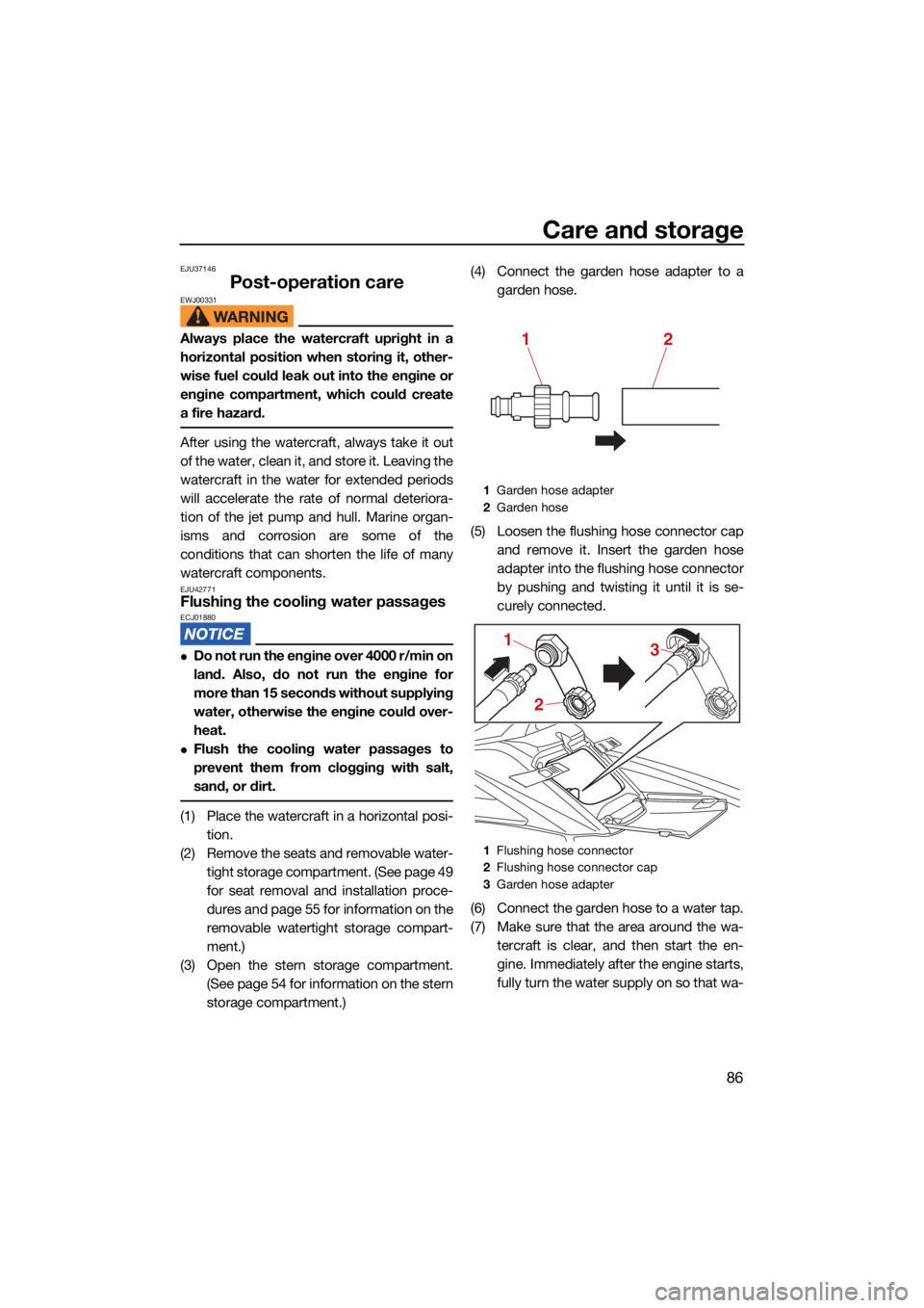
storage compartment.) (4) Connect the garden hose adapter to a
garden hose.
(5) Loosen the flushing hose connector cap and remove it. Insert the garden hose
adapter into the flushing hose connector
by pushing and twisting it until it is se-
curely connected.
(6) Connect the garden hose to a water tap.
(7) Make sure that the area around the wa- tercraft is clear, and then start the en-
gine. Immediately after the engine starts,
fully turn the water supply on so that wa-
1Garden hose adapter
2 Garden hose
1 Flushing hose connector
2 Flushing hose connector cap
3 Garden hose adapter
12
2
1
3
UF3X72E0.book Page 86 Friday, May 29, 2020 10:09 AM
Page 94 of 116
Care and storage
87
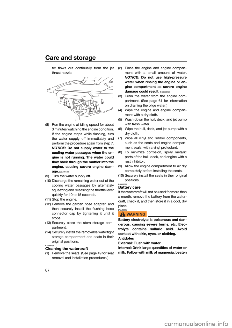
ter flows out continually from the jet
thrust nozzle.
(8) Run the engine at idling speed for about 3 minutes watching the engine condition.
If the engine stops while flushing, turn
the water supply off immediately and
perform the procedure again from step 7.
NOTICE: Do not supply water to the
cooling water passages when the en-
gine is not running. The water could
flow back through the muffler into the
engine, causing severe engine dam-
age.
[ECJ00123]
(9) Turn the water supply off.
(10) Discharge the remaining water out of the cooling water passages by alternately
squeezing and releasing the throttle lever
quickly for 10 to 15 seconds.
(11) Stop the engine.
(12) Remove the garden hose adapter, and then securely install the flushing hose
connector cap by tightening it until it
stops.
(13) Securely close the stern storage com- partment.
(14) Securely install the removable watertight storage compartment and seats in their
original positions.
EJU33736Cleaning the watercraft
(1) Remove the seats. (See page 49 for seatremoval and installation procedures.) (2) Rinse the engine and engine compart-
ment with a small amount of water.
NOTICE: Do not use high-pressure
water when rinsing the engine or en-
gine compartment as severe engine
damage could result.
[ECJ00572]
(3) Drain the water from the engine com- partment. (See page 61 for information
on draining the bilge water.)
(4) Wipe the engine and engine compart- ment with a dry cloth.
(5) Wash down the hull, deck, and jet pump with fresh water.
(6) Wipe the hull, deck, and jet pump with a dry cloth.
(7) Wipe all vinyl and rubber components, such as the seats and engine compart-
ment seals, with a vinyl protectant.
(8) To minimize corrosion, spray metallic parts of the hull, deck, and engine with a
rust inhibitor.
(9) Allow the engine compartment to air dry completely before installing the seats.
(10) Securely install the seats in their original positions.
EJU3368ABattery care
If the watercraft will not be used for more than
a month, remove the battery from the water-
craft, check it, and then store it in a cool, dry
place.
EWJ00792
Battery electrolyte is poisonous and dan-
gerous, causing severe burns, etc. Elec-
trolyte contains sulfuric acid. Avoid
contact with skin, eyes, or clothing.
Antidotes
External: Flush with water.
Internal: Drink large quantities of water or
milk. Follow with milk of magnesia, beaten
UF3X72E0.book Page 87 Friday, May 29, 2020 10:09 AM
Page 98 of 116
Maintenance
91
EJU33769
Maintenance
Periodic checks and lubrication will keep
your watercraft in the safest and most effi-
cient condition possible. Therefore, make
sure to carry out the periodic maintenance.
Safety is an obligation of the watercraft own-
er. Proper maintenance must be carried out
to keep the exhaust emission and sound lev-
els within the regulated limits. The most im-
portant points of watercraft inspection and
lubrication are explained on the following
pages.
See a Yamaha dealer for genuine Yamaha re-
placement parts and optional accessories
designed for your watercraft.
Remember, failures that are the result of the
installation of parts or accessories which are
not qualitatively equivalent to genuine
Yamaha parts are not covered by the limited warranty.
Maintenance, replacement, or repair of
the emission control devices and system
may be performed by any marine SI engine
repair establishment or individual. War-
ranty repair, however, must be performed
at an authorized Yamaha marine dealer-
ship.
EWJ00312
Be sure to turn off the engine when you
perform maintenance unless otherwise
specified. If you are not familiar with ma-
chine servicing, this work should be done
by a Yamaha dealer or other qualified me-
chanic.
EJU42023Removing and installing the engine
cover
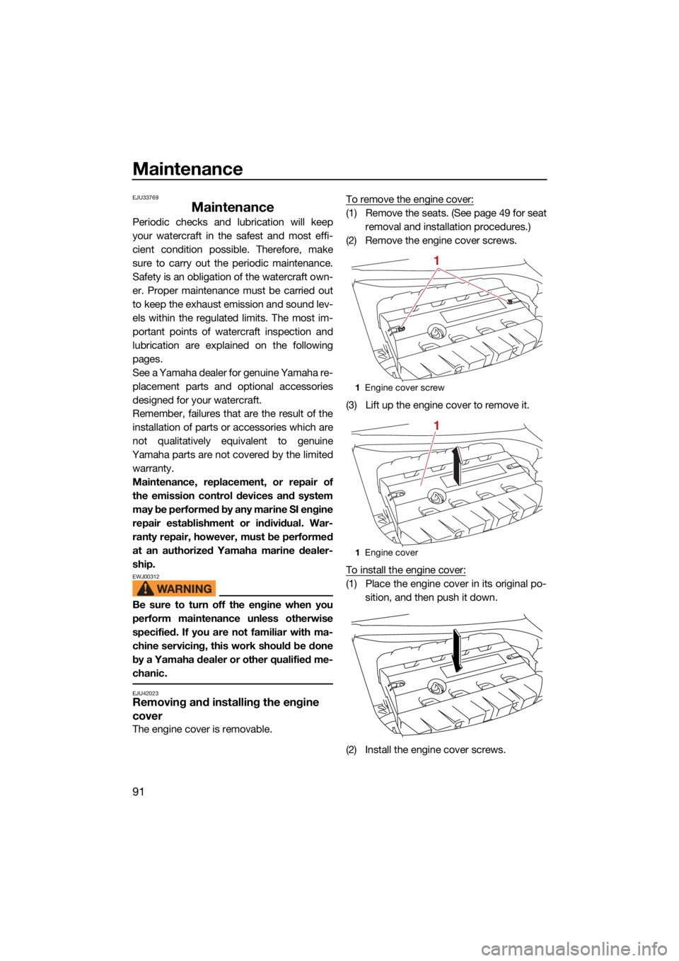
The engine cover is removable. To remove the engine cover:
(1) Remove the seats. (See page 49 for seat
removal and installation procedures.)
(2) Remove the engine cover screws.
(3) Lift up the engine cover to remove it.
To install the engine cover:
(1) Place the engine cover in its original po- sition, and then push it down.
(2) Install the engine cover screws.
1 Engine cover screw
1 Engine cover
1
1
UF3X72E0.book Page 91 Friday, May 29, 2020 10:09 AM
Page 109 of 116
Trouble recovery
102
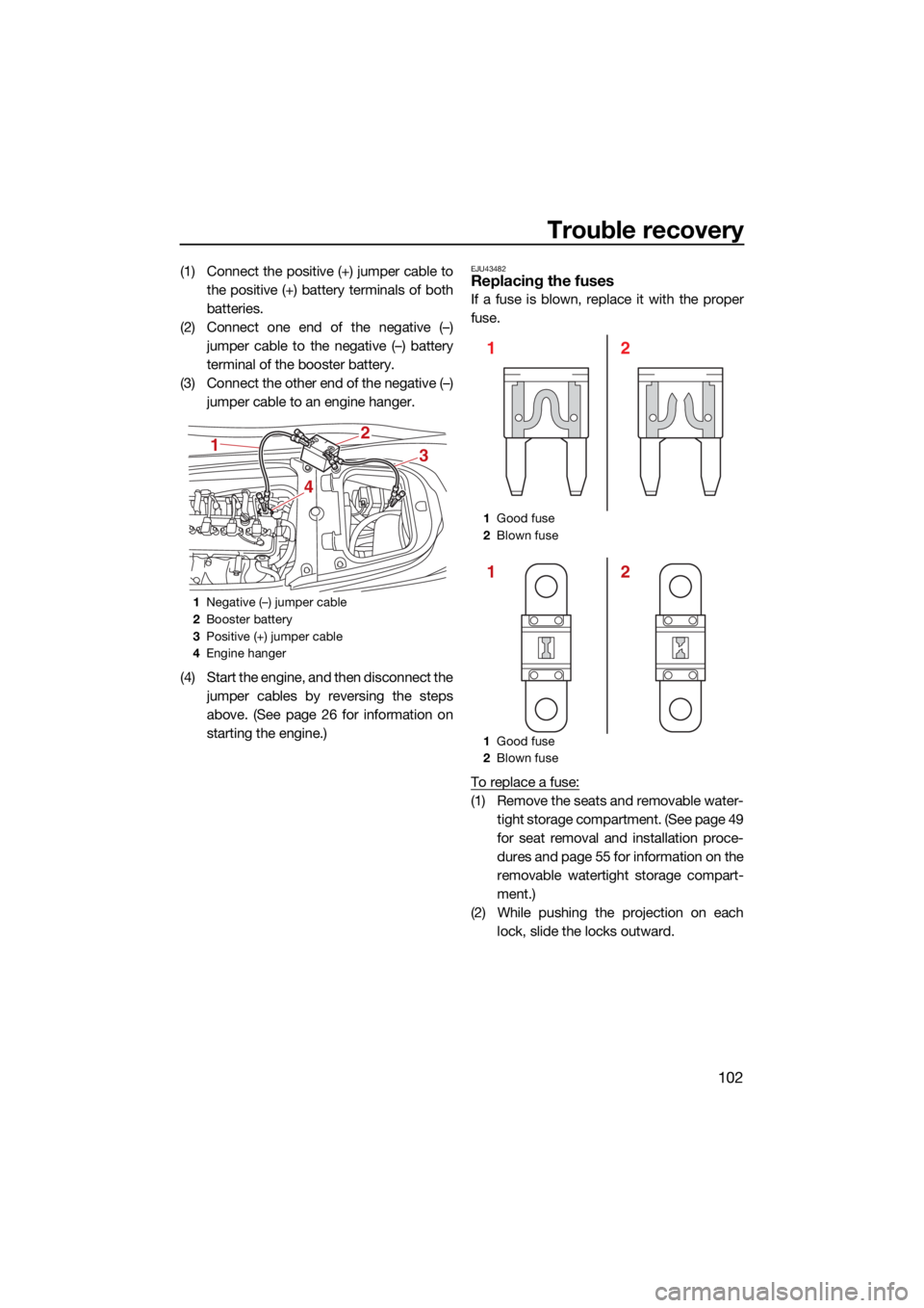
(1) Connect the positive (+) jumper cable tothe positive (+) battery terminals of both
batteries.
(2) Connect one end of the negative (–) jumper cable to the negative (–) battery
terminal of the booster battery.
(3) Connect the other end of the negative (–) jumper cable to an engine hanger.
(4) Start the engine, and then disconnect the jumper cables by reversing the steps
above. (See page 26 for information on
starting the engine.)EJU43482Replacing the fuses
If a fuse is blown, replace it with the proper
fuse.
To replace a fuse:
(1) Remove the seats and removable water-tight storage compartment. (See page 49
for seat removal and installation proce-
dures and page 55 for information on the
removable watertight storage compart-
ment.)
(2) While pushing the projection on each lock, slide the locks outward.
1Negative (–) jumper cable
2 Booster battery
3 Positive (+) jumper cable
4 Engine hanger
1
4
3
2
1Good fuse
2 Blown fuse
1 Good fuse
2 Blown fuse
2
1
2
1
UF3X72E0.book Page 102 Friday, May 29, 2020 10:09 AM
Page 111 of 116
Trouble recovery
104
(7) Securely install the fuse box cover in itsoriginal position.
(8) Securely install the electrical box cover in its original position.
(9) Slide the locks to their original positions to securely lock the electrical box cover
in place.
(10) Securely install the removable watertight storage compartment and seats in their
original positions.
If the fuse immediately blows again, the elec-
trical system may be defective. If this occurs,
have a Yamaha dealer service the watercraft.
EJU34716Towing the watercraftEWJ00812
The operator of the towing boat must
keep speed to a minimum and avoid
traffic or obstacles which could be a
hazard to the operator on the water-
craft.
The towline should be long enough so
that the watercraft will not collide with
the towing boat when slowing down.
If the watercraft becomes inoperative in the
water, it can be towed to shore. To tow the watercraft:
Use a towline that is three times the com-
bined length of the towing boat and the wa-
tercraft.
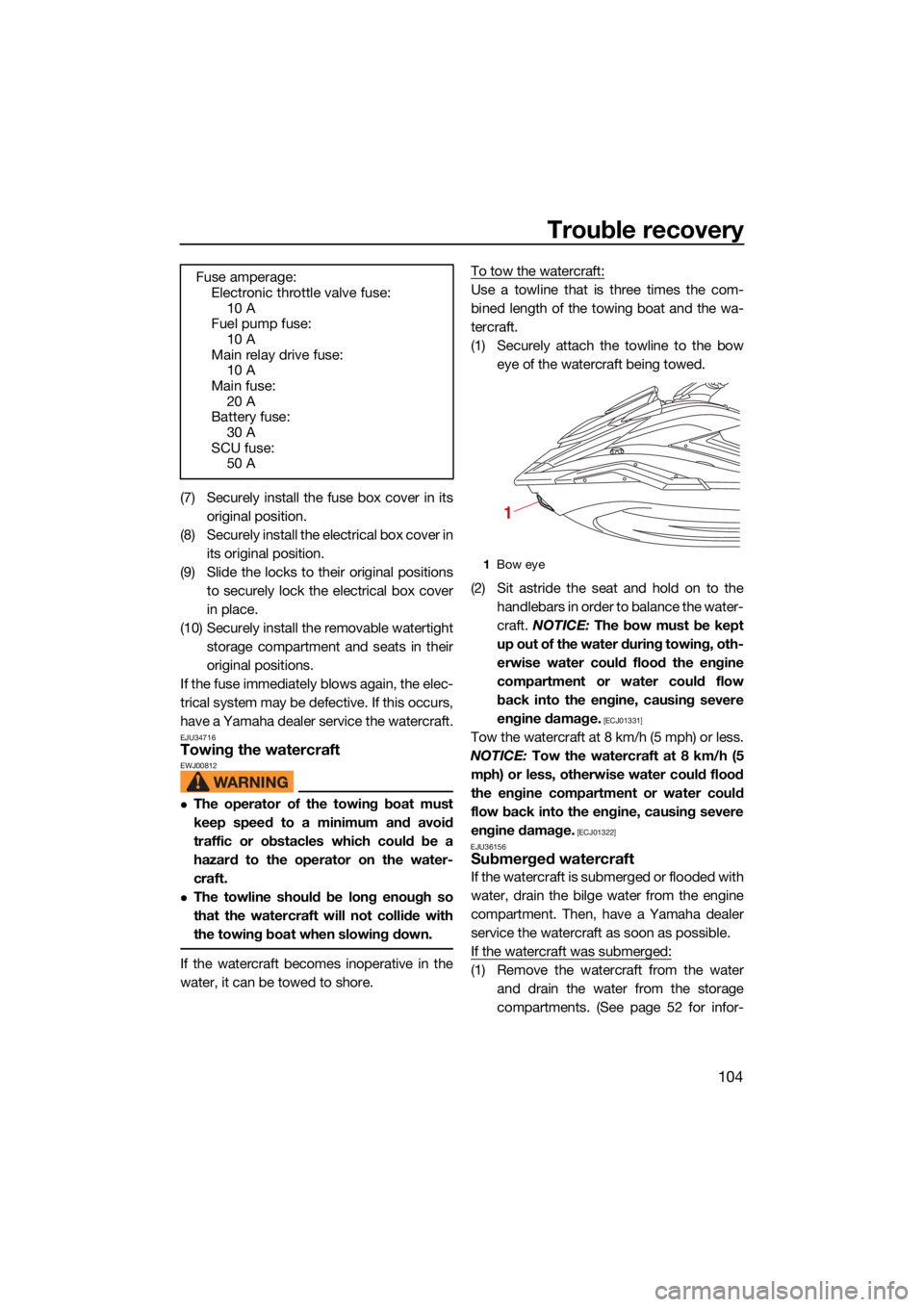
(1) Securely attach the towline to the bow
eye of the watercraft being towed.
(2) Sit astride the seat and hold on to the handlebars in order to balance the water-
craft. NOTICE: The bow must be kept
up out of the water during towing, oth-
erwise water could flood the engine
compartment or water could flow
back into the engine, causing severe
engine damage.
[ECJ01331]
Tow the watercraft at 8 km/h (5 mph) or less.
NOTICE: Tow the watercraft at 8 km/h (5
mph) or less, otherwise water could flood
the engine compartment or water could
flow back into the engine, causing severe
engine damage.
[ECJ01322]
EJU36156
Submerged watercraft
If the watercraft is submerged or flooded with
water, drain the bilge water from the engine
compartment. Then, have a Yamaha dealer
service the watercraft as soon as possible.
If the watercraft was submerged:
(1) Remove the watercraft from the water and drain the water from the storage
compartments. (See page 52 for infor-
Fuse amperage:
Electronic throttle valve fuse:
10 A
Fuel pump fuse: 10 A
Main relay drive fuse: 10 A
Main fuse:
20 A
Battery fuse: 30 A
SCU fuse: 50 A
1Bow eye
1
UF3X72E0.book Page 104 Friday, May 29, 2020 10:09 AM