AUX YAMAHA FZ6 S 2006 Owners Manual
[x] Cancel search | Manufacturer: YAMAHA, Model Year: 2006, Model line: FZ6 S, Model: YAMAHA FZ6 S 2006Pages: 92, PDF Size: 4.55 MB
Page 7 of 92
TABLE OF CONTENTS
Replacing the license plate light
bulb ........................................... 6-35
Replacing an auxiliary light bulb ... 6-36
Troubleshooting ............................ 6-36
Troubleshooting charts ................. 6-37
MOTORCYCLE CARE AND
STORAGE.......................................... 7-1
Care ................................................ 7-1
Storage ...........................................7-3
SPECIFICATIONS ............................. 8-1
CONSUMER INFORMATION............. 9-1
Identification numbers .................... 9-1
U4P5E0E0.book Page 2 Wednesday, December 14, 2005 11:15 AM
Page 16 of 92
INSTRUMENT AND CONTROL FUNCTIONS
3-2
3
EAU10471
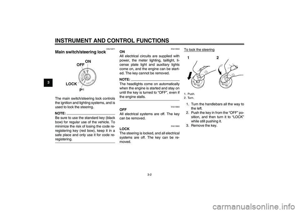
Main switch/steering lock The main switch/steering lock controls
the ignition and lighting systems, and is
used to lock the steering.NOTE:Be sure to use the standard key (black
bow) for regular use of the vehicle. To
minimize the risk of losing the code re-
registering key (red bow), keep it in a
safe place and only use it for code re-registering.
EAU10550
ON
All electrical circuits are supplied with
power, the meter lighting, taillight, li-
cense plate light and auxiliary lights
come on, and the engine can be start-
ed. The key cannot be removed.NOTE:The headlights come on automatically
when the engine is started and stay on
until the key is turned to “OFF”, even ifthe engine stalls.
EAU10660
OFF
All electrical systems are off. The key
can be removed.
EAU10680
LOCK
The steering is locked, and all electrical
systems are off. The key can be re-
moved.To lock the steering
1. Turn the handlebars all the way to
the left.
2. Push the key in from the “OFF” po-
sition, and then turn it to “LOCK”
while still pushing it.
3. Remove the key.1. Push.
2. Turn.
U4P5E0E0.book Page 2 Wednesday, December 14, 2005 11:15 AM
Page 17 of 92
INSTRUMENT AND CONTROL FUNCTIONS
3-3
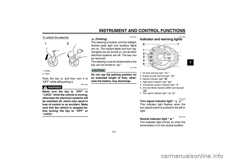
3 To unlock the steering
Push the key in, and then turn it to
“OFF” while still pushing it.
WARNING
EWA10060
Never turn the key to “OFF” or
“LOCK” while the vehicle is moving,
otherwise the electrical systems will
be switched off, which may result in
loss of control or an accident. Make
sure that the vehicle is stopped be-
fore turning the key to “OFF” or“LOCK”.
EAU10941
(Parking)
The steering is locked, and the taillight,
license plate light and auxiliary lights
are on. The hazard lights and turn sig-
nal lights can be turned on, but all other
electrical systems are off. The key can
be removed.
The steering must be locked before the
key can be turned to “”.
CAUTION:
ECA11020
Do not use the parking position for
an extended length of time, other-wise the battery may discharge.
EAU11003
Indicator and warning lights
EAU11020
Turn signal indicator light “”
This indicator light flashes when the
turn signal switch is pushed to the left or
right.
EAU11060
Neutral indicator light “”
This indicator light comes on when the
transmission is in the neutral position.
1. Push.
2. Turn.
1. Oil level warning light “”
2. Engine trouble warning light “”
3. Neutral indicator light “”
4. High beam indicator light “”
5. Immobilizer system indicator light “”
6. Anti-lock Brake System (ABS) warning light
“”
7. Turn signal indicator light “”
ABS
U4P5E0E0.book Page 3 Wednesday, December 14, 2005 11:15 AM
Page 77 of 92
PERIODIC MAINTENANCE AND MINOR REPAIR
6-36
6
EAU32831
Replacing an auxiliary light
bulb This model is equipped with two auxil-
iary lights. If an auxiliary light bulb burns
out, replace it as follows.
1. Remove panel B (if replacing the
left auxiliary light bulb) or panel A
(if replacing the right auxiliary light
bulb). (See page 6-6.)
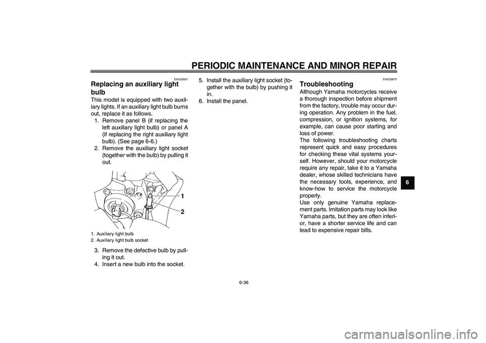
2. Remove the auxiliary light socket
(together with the bulb) by pulling it
out.
3. Remove the defective bulb by pull-
ing it out.
4. Insert a new bulb into the socket.5. Install the auxiliary light socket (to-
gether with the bulb) by pushing it
in.
6. Install the panel.
EAU25870
Troubleshooting Although Yamaha motorcycles receive
a thorough inspection before shipment
from the factory, trouble may occur dur-
ing operation. Any problem in the fuel,
compression, or ignition systems, for
example, can cause poor starting and
loss of power.
The following troubleshooting charts
represent quick and easy procedures
for checking these vital systems your-
self. However, should your motorcycle
require any repair, take it to a Yamaha
dealer, whose skilled technicians have
the necessary tools, experience, and
know-how to service the motorcycle
properly.
Use only genuine Yamaha replace-
ment parts. Imitation parts may look like
Yamaha parts, but they are often inferi-
or, have a shorter service life and can
lead to expensive repair bills.
1. Auxiliary light bulb
2. Auxiliary light bulb socket
U4P5E0E0.book Page 36 Wednesday, December 14, 2005 11:15 AM
Page 86 of 92
SPECIFICATIONS
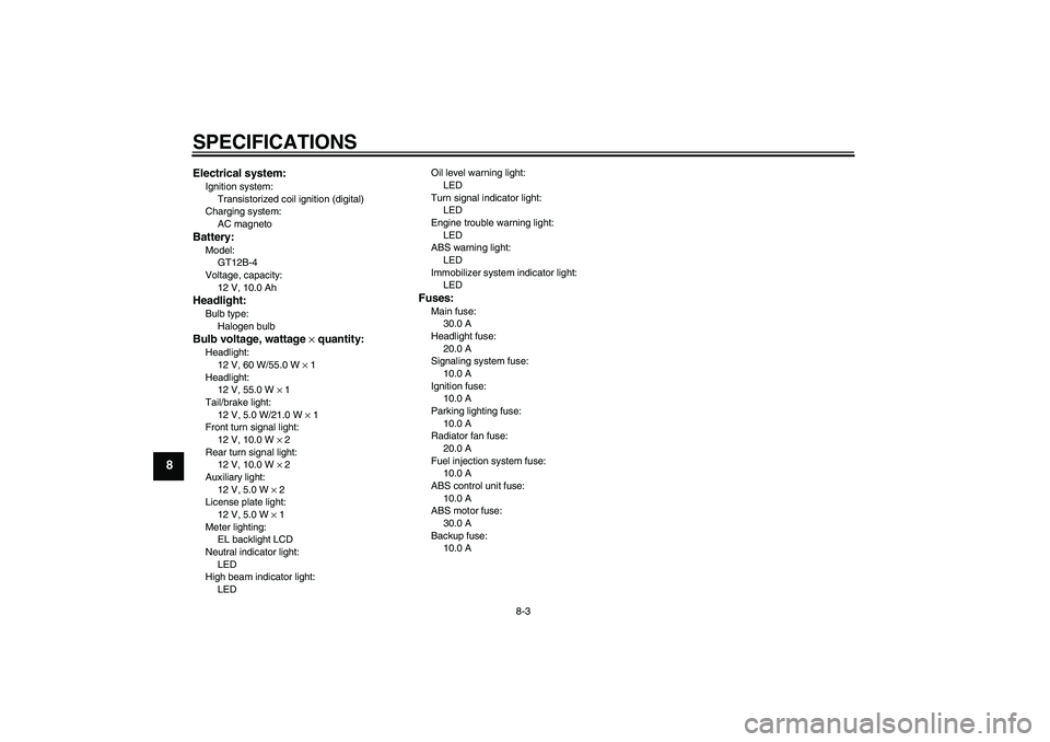
8-3
8
Electrical system:Ignition system:
Transistorized coil ignition (digital)
Charging system:
AC magnetoBattery:Model:
GT12B-4
Voltage, capacity:
12 V, 10.0 AhHeadlight:Bulb type:
Halogen bulbBulb voltage, wattage × quantity:Headlight:
12 V, 60 W/55.0 W × 1
Headlight:
12 V, 55.0 W × 1
Tail/brake light:
12 V, 5.0 W/21.0 W × 1
Front turn signal light:
12 V, 10.0 W × 2
Rear turn signal light:
12 V, 10.0 W × 2
Auxiliary light:
12 V, 5.0 W × 2
License plate light:
12 V, 5.0 W × 1
Meter lighting:
EL backlight LCD
Neutral indicator light:
LED
High beam indicator light:
LEDOil level warning light:
LED
Turn signal indicator light:
LED
Engine trouble warning light:
LED
ABS warning light:
LED
Immobilizer system indicator light:
LED
Fuses:Main fuse:
30.0 A
Headlight fuse:
20.0 A
Signaling system fuse:
10.0 A
Ignition fuse:
10.0 A
Parking lighting fuse:
10.0 A
Radiator fan fuse:
20.0 A
Fuel injection system fuse:
10.0 A
ABS control unit fuse:
10.0 A
ABS motor fuse:
30.0 A
Backup fuse:
10.0 A
U4P5E0E0.book Page 3 Wednesday, December 14, 2005 11:15 AM
Page 89 of 92
INDEX
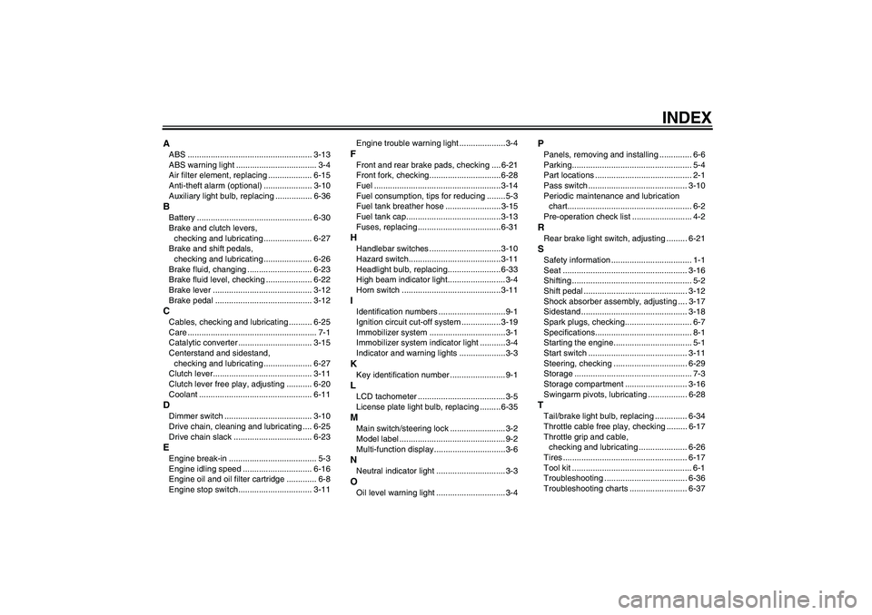
AABS ...................................................... 3-13
ABS warning light ................................... 3-4
Air filter element, replacing ................... 6-15
Anti-theft alarm (optional) ..................... 3-10
Auxiliary light bulb, replacing ................ 6-36BBattery .................................................. 6-30
Brake and clutch levers,
checking and lubricating ..................... 6-27
Brake and shift pedals,
checking and lubricating ..................... 6-26
Brake fluid, changing ............................ 6-23
Brake fluid level, checking .................... 6-22
Brake lever ........................................... 3-12
Brake pedal .......................................... 3-12CCables, checking and lubricating .......... 6-25
Care ........................................................ 7-1
Catalytic converter ................................ 3-15
Centerstand and sidestand,
checking and lubricating ..................... 6-27
Clutch lever........................................... 3-11
Clutch lever free play, adjusting ........... 6-20
Coolant ................................................. 6-11DDimmer switch ...................................... 3-10
Drive chain, cleaning and lubricating .... 6-25
Drive chain slack .................................. 6-23EEngine break-in ...................................... 5-3
Engine idling speed .............................. 6-16
Engine oil and oil filter cartridge ............. 6-8
Engine stop switch................................ 3-11Engine trouble warning light .................... 3-4
FFront and rear brake pads, checking .... 6-21
Front fork, checking...............................6-28
Fuel ....................................................... 3-14
Fuel consumption, tips for reducing ........ 5-3
Fuel tank breather hose ........................ 3-15
Fuel tank cap......................................... 3-13
Fuses, replacing .................................... 6-31HHandlebar switches ............................... 3-10
Hazard switch........................................ 3-11
Headlight bulb, replacing....................... 6-33
High beam indicator light......................... 3-4
Horn switch ........................................... 3-11IIdentification numbers ............................. 9-1
Ignition circuit cut-off system ................. 3-19
Immobilizer system .................................3-1
Immobilizer system indicator light ........... 3-4
Indicator and warning lights .................... 3-3KKey identification number ........................ 9-1LLCD tachometer ...................................... 3-5
License plate light bulb, replacing ......... 6-35MMain switch/steering lock ........................ 3-2
Model label .............................................. 9-2
Multi-function display...............................3-6NNeutral indicator light .............................. 3-3OOil level warning light .............................. 3-4
PPanels, removing and installing .............. 6-6
Parking.................................................... 5-4
Part locations .......................................... 2-1
Pass switch ........................................... 3-10
Periodic maintenance and lubrication
chart...................................................... 6-2
Pre-operation check list .......................... 4-2RRear brake light switch, adjusting ......... 6-21SSafety information ................................... 1-1
Seat ...................................................... 3-16
Shifting .................................................... 5-2
Shift pedal ............................................. 3-12
Shock absorber assembly, adjusting .... 3-17
Sidestand .............................................. 3-18
Spark plugs, checking............................. 6-7
Specifications.......................................... 8-1
Starting the engine.................................. 5-1
Start switch ........................................... 3-11
Steering, checking ................................ 6-29
Storage ................................................... 7-3
Storage compartment ........................... 3-16
Swingarm pivots, lubricating ................. 6-28TTail/brake light bulb, replacing .............. 6-34
Throttle cable free play, checking ......... 6-17
Throttle grip and cable,
checking and lubricating ..................... 6-26
Tires ...................................................... 6-17
Tool kit .................................................... 6-1
Troubleshooting .................................... 6-36
Troubleshooting charts ......................... 6-37
U4P5E0E0.book Page 1 Wednesday, December 14, 2005 11:15 AM