display YAMAHA FZR 2009 Owners Manual
[x] Cancel search | Manufacturer: YAMAHA, Model Year: 2009, Model line: FZR, Model: YAMAHA FZR 2009Pages: 96, PDF Size: 7.01 MB
Page 39 of 96

Features and functions
32
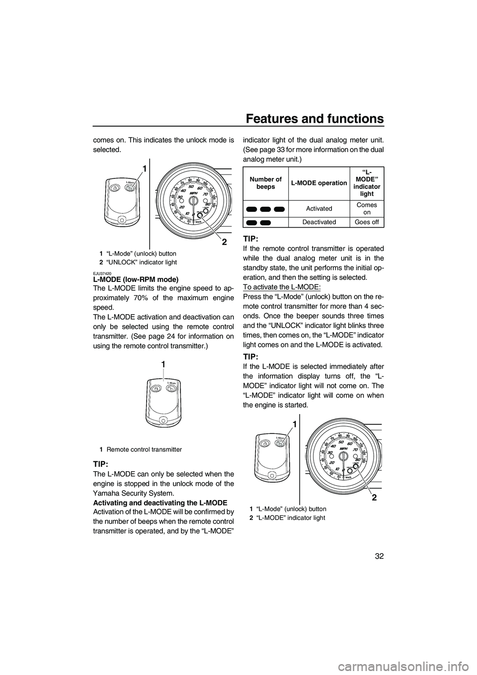
comes on. This indicates the unlock mode is
selected.
EJU37420L-MODE (low-RPM mode)
The L-MODE limits the engine speed to ap-
proximately 70% of the maximum engine
speed.
The L-MODE activation and deactivation can
only be selected using the remote control
transmitter. (See page 24 for information on
using the remote control transmitter.)
TIP:
The L-MODE can only be selected when the
engine is stopped in the unlock mode of the
Yamaha Security System.
Activating and deactivating the L-MODE
Activation of the L-MODE will be confirmed by
the number of beeps when the remote control
transmitter is operated, and by the “L-MODE”indicator light of the dual analog meter unit.
(See page 33 for more information on the dual
analog meter unit.)
TIP:
If the remote control transmitter is operated
while the dual analog meter unit is in the
standby state, the unit performs the initial op-
eration, and then the setting is selected.
To activate the L-MODE:
Press the “L-Mode” (unlock) button on the re-
mote control transmitter for more than 4 sec-
onds. Once the beeper sounds three times
and the “UNLOCK” indicator light blinks three
times, then comes on, the “L-MODE” indicator
light comes on and the L-MODE is activated.
TIP:
If the L-MODE is selected immediately after
the information display turns off, the “L-
MODE” indicator light will not come on. The
“L-MODE” indicator light will come on when
the engine is started.
1“L-Mode” (unlock) button
2“UNLOCK” indicator light
1Remote control transmitter
2
1
Number of
beepsL-MODE operation“L-
MODE”
indicator
light
ActivatedComes
on
Deactivated Goes off
1“L-Mode” (unlock) button
2“L-MODE” indicator light
2
1
UF2R70E0.book Page 32 Thursday, November 6, 2008 10:05 AM
Page 40 of 96

Features and functions
33
To deactivate the L-MODE:
Press the “L-Mode” (unlock) button on the re-
mote control transmitter for more than 4 sec-
onds. Once the beeper sounds two times and
the “UNLOCK” indicator light blinks two times,
then comes on, the “L-MODE” indicator light
goes off and the L-MODE is deactivated.
When the L-MODE is deactivated, the water-
craft returns to the normal operation mode.
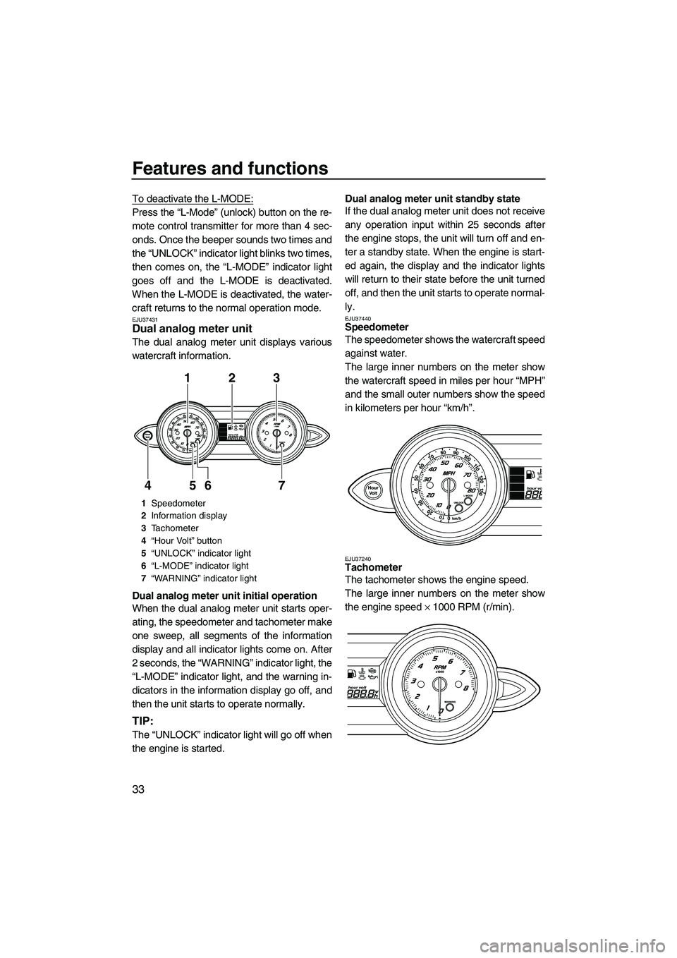
EJU37431Dual analog meter unit
The dual analog meter unit displays various
watercraft information.
Dual analog meter unit initial operation
When the dual analog meter unit starts oper-
ating, the speedometer and tachometer make
one sweep, all segments of the information
display and all indicator lights come on. After
2 seconds, the “WARNING” indicator light, the
“L-MODE” indicator light, and the warning in-
dicators in the information display go off, and
then the unit starts to operate normally.
TIP:
The “UNLOCK” indicator light will go off when
the engine is started.Dual analog meter unit standby state
If the dual analog meter unit does not receive
any operation input within 25 seconds after
the engine stops, the unit will turn off and en-
ter a standby state. When the engine is start-
ed again, the display and the indicator lights
will return to their state before the unit turned
off, and then the unit starts to operate normal-
ly.
EJU37440Speedometer
The speedometer shows the watercraft speed
against water.
The large inner numbers on the meter show
the watercraft speed in miles per hour “MPH”
and the small outer numbers show the speed
in kilometers per hour “km/h”.
EJU37240Tachometer
The tachometer shows the engine speed.
The large inner numbers on the meter show
the engine speed × 1000 RPM (r/min).
1Speedometer
2Information display
3Tachometer
4“Hour Volt” button
5“UNLOCK” indicator light
6“L-MODE” indicator light
7“WARNING” indicator light
123
7 6 5 4
UF2R70E0.book Page 33 Thursday, November 6, 2008 10:05 AM
Page 41 of 96

Features and functions
34
EJU37250Information display
The information display shows watercraft op-
erating conditions.
EJU37261Hour meter/voltmeter
The hour meter/voltmeter can be used as an
hour meter or a voltmeter.
TIP:
The hour meter is selected at the Yamaha
factory.
Hour meter
The hour meter shows the hours of engine op-
eration that have elapsed since the watercraft
was new.To switch to the hour meter from the voltme-
ter:
Push the “Hour Volt” button for at least 1 sec-
ond. The display switches from the voltmeter
to the hour meter.
Voltmeter
The voltmeter shows the battery voltage.
When the battery voltage is normal, the volt-
meter displays approximately 12 volts.
If the battery voltage has dropped significant-
ly, “LO” is displayed on the voltmeter. If the
battery voltage has risen significantly, “HI” is
displayed. If “HI” or “LO” is displayed, immedi-
ately return to shore and have a Yamaha
dealer service the watercraft.
1Fuel level meter
2Fuel indicator
3Engine overheat warning indicator
4Check engine warning indicator
5Oil pressure warning indicator
6Hour meter/voltmeter
1Hour meter/voltmeter
12345
6
1
1“Hour Volt” button
2Hour meter
1
2
UF2R70E0.book Page 34 Thursday, November 6, 2008 10:05 AM
Page 42 of 96

Features and functions
35
To switch to the voltmeter from the hour
meter:
Push the “Hour Volt” button for at least 1 sec-
ond. The display switches from the hour
meter to the voltmeter.
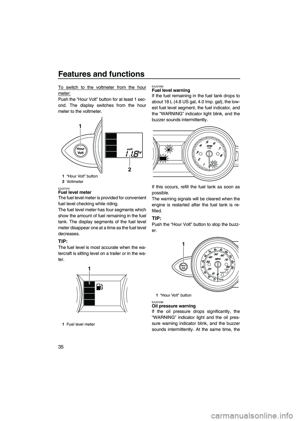
EJU37270Fuel level meter
The fuel level meter is provided for convenient
fuel level checking while riding.
The fuel level meter has four segments which
show the amount of fuel remaining in the fuel
tank. The display segments of the fuel level
meter disappear one at a time as the fuel level
decreases.
TIP:
The fuel level is most accurate when the wa-
tercraft is sitting level on a trailer or in the wa-
ter.
EJU37280Fuel level warning
If the fuel remaining in the fuel tank drops to
about 18 L (4.8 US gal, 4.0 Imp. gal), the low-
est fuel level segment, the fuel indicator, and
the “WARNING” indicator light blink, and the
buzzer sounds intermittently.
If this occurs, refill the fuel tank as soon as
possible.
The warning signals will be cleared when the
engine is restarted after the fuel tank is re-
filled.
TIP:
Push the “Hour Volt” button to stop the buzz-
er.
EJU37290Oil pressure warning
If the oil pressure drops significantly, the
“WARNING” indicator light and the oil pres-
sure warning indicator blink, and the buzzer
sounds intermittently. At the same time, the
1“Hour Volt” button
2Vo l t m e t e r
1Fuel level meter
1
2
1
1“Hour Volt” button
1
UF2R70E0.book Page 35 Thursday, November 6, 2008 10:05 AM
Page 94 of 96

Index
A
Air filter element ....................................... 72
B
Battery ................................................ 47, 68
Battery, checking...................................... 76
Battery, jumping ....................................... 84
Beaching the watercraft ........................... 64
Bilge ......................................................... 47
Boarding alone ......................................... 58
Boarding and starting from a dock ........... 58
Boarding and starting in deep water ........ 58
Boarding and starting in shallow water .... 57
Boarding with a passenger....................... 59
Bow down................................................. 30
Bow eye ................................................... 30
Bow up ..................................................... 30
Builder’s plate............................................. 2
C
Capsized watercraft ................................. 61
Check engine warning.............................. 37
Cleaning the watercraft ............................ 68
Cooling water pilot outlets .................. 27, 52
Craft Identification Number (CIN) ............... 1
Cruising limitations ................................... 11
D
Docking the watercraft ............................. 64
Dual analog meter unit ....................... 33, 52
E
Emergency procedures ............................ 83
Engine break-in ........................................ 53
Engine compartment ................................ 45
Engine oil ................................................. 42
Engine oil and oil filter .............................. 72
Engine oil level ......................................... 45
Engine overheat warning ......................... 36
Engine serial number ................................. 1
Engine shut-off cord (lanyard) .................. 51
Engine shut-off switch .............................. 25
Engine stop switch ................................... 25
Enjoy your watercraft responsibly ............ 17
F
Fire extinguisher....................................... 48
Flushing the cooling system ..................... 67
Front storage compartment ...................... 37
Fuel .......................................................... 41Fuel and oil............................................... 41
Fuel injection system ................................ 78
Fuel level .................................................. 45
Fuel level meter ........................................ 35
Fuel level warning .................................... 35
Fuel system, checking .............................. 72
Fuel tank .................................................. 72
Fuel tank filler cap .................................... 24
Fuses, replacing ....................................... 84
G
Getting to know your watercraft ............... 56
Glove compartment .................................. 38
H
Hazard information ................................... 15
Hood ......................................................... 24
Hour meter/voltmeter ............................... 34
Hull and deck ........................................... 45
I
Identification numbers ................................ 1
Information display ................................... 34
J
Jet intake .................................................. 51
Jet intake and impeller, cleaning .............. 83
Jet thrust nozzle angle, checking ............. 72
Jumper cables, connecting ...................... 84
L
Labels, important ........................................ 3
Labels, other .............................................. 8
Labels, warning .......................................... 4
Launching the watercraft .......................... 53
Learning to operate your watercraft ......... 56
Leaving the watercraft .............................. 55
Limitations on who may operate the
watercraft .............................................. 10
L-MODE (low-RPM mode) ....................... 32
Lubrication................................................ 68
Lubrication points ..................................... 75
M
Main components, location of .................. 19
Maintenance and adjustments ................. 69
Model information....................................... 2
O
Oil pressure warning ................................ 35
Operating in weeded areas ...................... 64
Operating your watercraft ......................... 56
UF2R70E0.book Page 1 Thursday, November 6, 2008 10:05 AM