YAMAHA FZR SVHO 2014 Repair Manual
Manufacturer: YAMAHA, Model Year: 2014, Model line: FZR SVHO, Model: YAMAHA FZR SVHO 2014Pages: 106, PDF Size: 5.4 MB
Page 61 of 106
Pre-operation checks
55
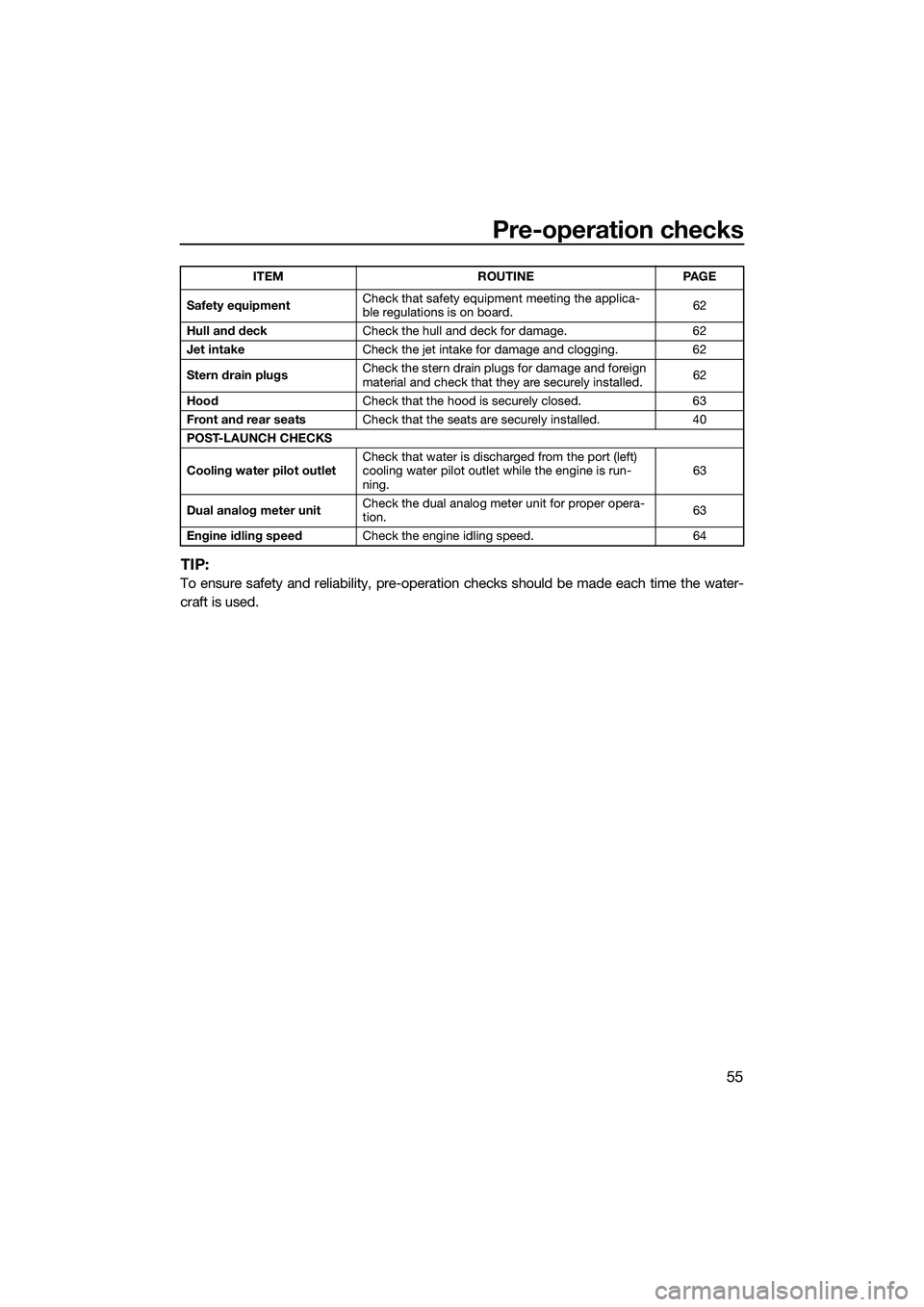
TIP:
To ensure safety and reliability, pre-operation checks should be made each time the water-
craft is used.
Safety equipment Check that safety equipment meeting the applica-
ble regulations is on board.
62
Hull and deck Check the hull and deck for damage. 62
Jet intake Check the jet intake for damage and clogging. 62
Stern drain plugs Check the stern drain plugs for damage and foreign
material and check that they are securely installed.
62
Hood Check that the hood is securely closed. 63
Front and rear seats Check that the seats are securely installed. 40
POST-LAUNCH CHECKS
Cooling water pilot outlet Check that water is discharged from the port (left)
cooling water pilot outlet while the engine is run-
ning. 63
Dual analog meter unit Check the dual analog meter unit for proper opera-
tion.
63
Engine idling speed Check the engine idling speed. 64
ITEM ROUTINE PAGE
UF3L70E0.book Page 55 Thursday, November 7, 2013 9:08 AM
Page 62 of 106
Pre-operation checks
56
EJU32282
Pre-operation check pointsEJU41312Pre-launch checks
Perform the pre-launch checks in the pre-op-
eration checklist while the watercraft is on
land.
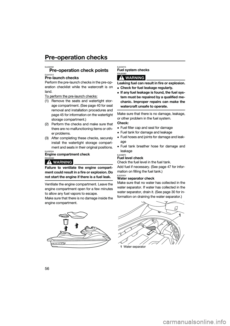
To perform the pre-launch checks:
(1) Remove the seats and watertight stor-age compartment. (See page 40 for seat
removal and installation procedures and
page 45 for information on the watertight
storage compartment.)
(2) Perform the checks and make sure that there are no malfunctioning items or oth-
er problems.
(3) After completing these checks, securely install the watertight storage compart-
ment and seats in their original positions.
EJU32334Engine compartment check
WARNING
EWJ00462
Failure to ventilate the engine compart-
ment could result in a fire or explosion. Do
not start the engine if there is a fuel leak.
Ventilate the engine compartment. Leave the
engine compartment open for a few minutes
to allow any fuel vapors to escape.
Make sure that there is no damage inside the
engine compartment.
EJU34215Fuel system checks
WARNING
EWJ00382
Leaking fuel can result in fire or explosion.
Check for fuel leakage regularly.
If any fuel leakage is found, the fuel sys-
tem must be repaired by a qualified me-
chanic. Improper repairs can make the
watercraft unsafe to operate.
Make sure that there is no damage, leakage,
or other problem in the fuel system.
Check:
Fuel filler cap and seal for damage
Fuel tank for damage and leakage
Fuel hoses and joints for damage and leak-
age
Fuel tank breather hose for damage and
leakage
EJU36875Fuel level check
Check the fuel level in the fuel tank.
Add fuel if necessary. (See page 47 for infor-
mation on filling the fuel tank.)
EJU32424Water separator check
Make sure that no water has collected in the
water separator. If water has collected in the
water separator, drain it. (See page 30 for in-
formation on draining the water separator.)
1Water separator
1
UF3L70E0.book Page 56 Thursday, November 7, 2013 9:08 AM
Page 63 of 106
Pre-operation checks
57
EJU40182Engine unit check
Check the exterior of the engine unit for dam-
age or other problem.
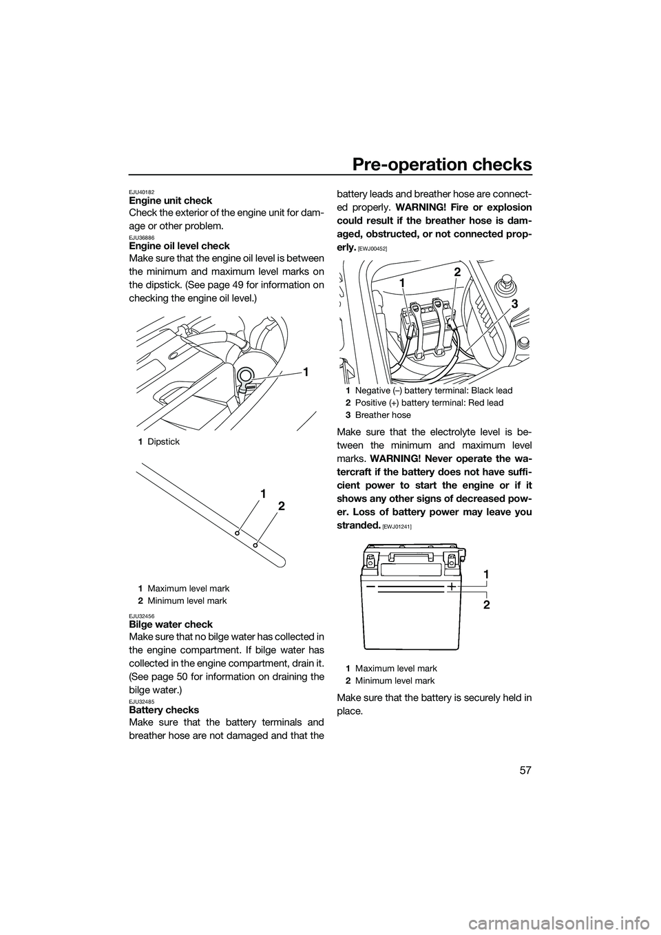
EJU36886Engine oil level check
Make sure that the engine oil level is between
the minimum and maximum level marks on
the dipstick. (See page 49 for information on
checking the engine oil level.)
EJU32456Bilge water check
Make sure that no bilge water has collected in
the engine compartment. If bilge water has
collected in the engine compartment, drain it.
(See page 50 for information on draining the
bilge water.)
EJU32485Battery checks
Make sure that the battery terminals and
breather hose are not damaged and that thebattery leads and breather hose are connect-
ed properly.
WARNING! Fire or explosion
could result if the breather hose is dam-
aged, obstructed, or not connected prop-
erly.
[EWJ00452]
Make sure that the electrolyte level is be-
tween the minimum and maximum level
marks. WARNING! Never operate the wa-
tercraft if the battery does not have suffi-
cient power to start the engine or if it
shows any other signs of decreased pow-
er. Loss of battery power may leave you
stranded.
[EWJ01241]
Make sure that the battery is securely held in
place.
1 Dipstick
1 Maximum level mark
2 Minimum level mark
1
2
1
1Negative (–) battery terminal: Black lead
2 Positive (+) battery terminal: Red lead
3 Breather hose
1 Maximum level mark
2 Minimum level mark
12
3
UF3L70E0.book Page 57 Thursday, November 7, 2013 9:08 AM
Page 64 of 106
Pre-operation checks
58
EJU32614Steering system checks
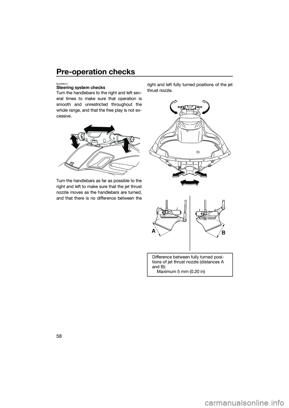
Turn the handlebars to the right and left sev-
eral times to make sure that operation is
smooth and unrestricted throughout the
whole range, and that the free play is not ex-
cessive.
Turn the handlebars as far as possible to the
right and left to make sure that the jet thrust
nozzle moves as the handlebars are turned,
and that there is no difference between theright and left fully turned positions of the jet
thrust nozzle.
Difference between fully turned posi-
tions of jet thrust nozzle (distances A
and B):
Maximum 5 mm (0.20 in)
UF3L70E0.book Page 58 Thursday, November 7, 2013 9:08 AM
Page 65 of 106
Pre-operation checks
59
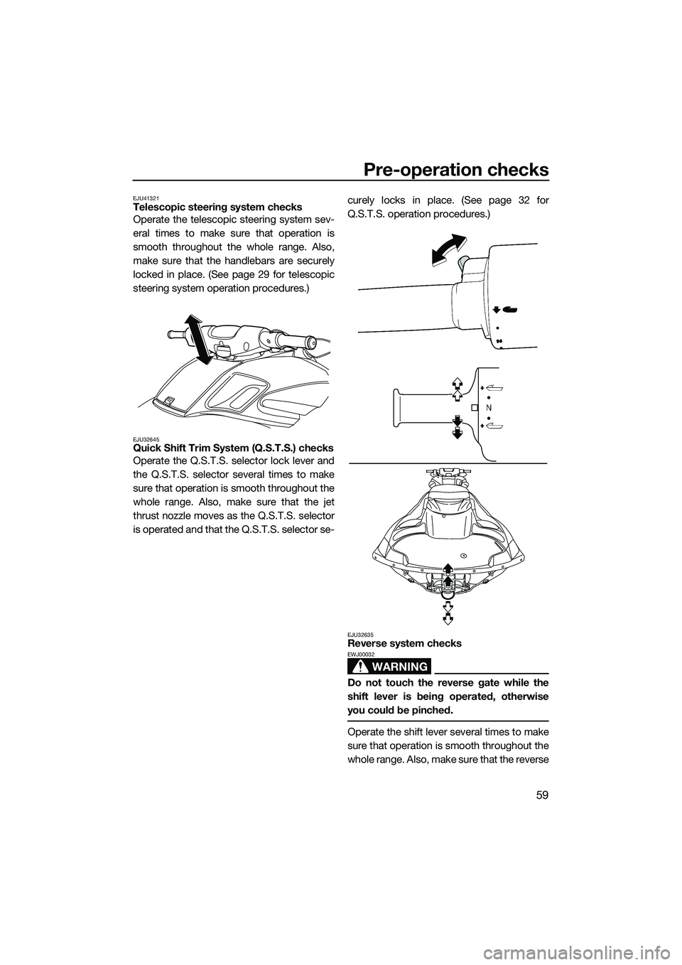
EJU41321Telescopic steering system checks
Operate the telescopic steering system sev-
eral times to make sure that operation is
smooth throughout the whole range. Also,
make sure that the handlebars are securely
locked in place. (See page 29 for telescopic
steering system operation procedures.)
EJU32645Quick Shift Trim System (Q.S.T.S.) checks
Operate the Q.S.T.S. selector lock lever and
the Q.S.T.S. selector several times to make
sure that operation is smooth throughout the
whole range. Also, make sure that the jet
thrust nozzle moves as the Q.S.T.S. selector
is operated and that the Q.S.T.S. selector se-curely locks in place. (See page 32 for
Q.S.T.S. operation procedures.)
EJU32635Reverse system checks
WARNING
EWJ00032
Do not touch the reverse gate while the
shift lever is being operated, otherwise
you could be pinched.
Operate the shift lever several times to make
sure that operation is smooth throughout the
whole range. Also, make sure that the reverse
UF3L70E0.book Page 59 Thursday, November 7, 2013 9:35 AM
Page 66 of 106
Pre-operation checks
60
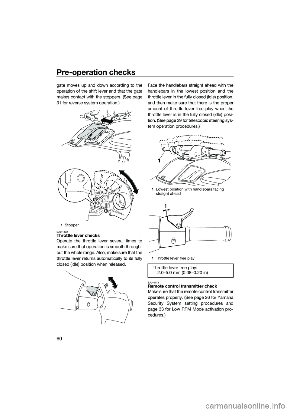
gate moves up and down according to the
operation of the shift lever and that the gate
makes contact with the stoppers. (See page
31 for reverse system operation.)
EJU41432Throttle lever checks
Operate the throttle lever several times to
make sure that operation is smooth through-
out the whole range. Also, make sure that the
throttle lever returns automatically to its fully
closed (idle) position when released.Face the handlebars straight ahead with the
handlebars in the lowest position and the
throttle lever in the fully closed (idle) position,
and then make sure that there is the proper
amount of throttle lever free play when the
throttle lever is in the fully closed (idle) posi-
tion. (See page 29 for telescopic steering sys-
tem operation procedures.)
EJU40113Remote control transmitter check
Make sure that the remote control transmitter
operates properly. (See page 26 for Yamaha
Security System setting procedures and
page 33 for Low RPM Mode activation pro-
cedures.)
1
Stopper
1
1Lowest position with handlebars facing
straight ahead
1 Throttle lever free play
Throttle lever free play:
2.0–5.0 mm (0.08–0.20 in)
1
1
UF3L70E0.book Page 60 Thursday, November 7, 2013 9:35 AM
Page 67 of 106
Pre-operation checks
61
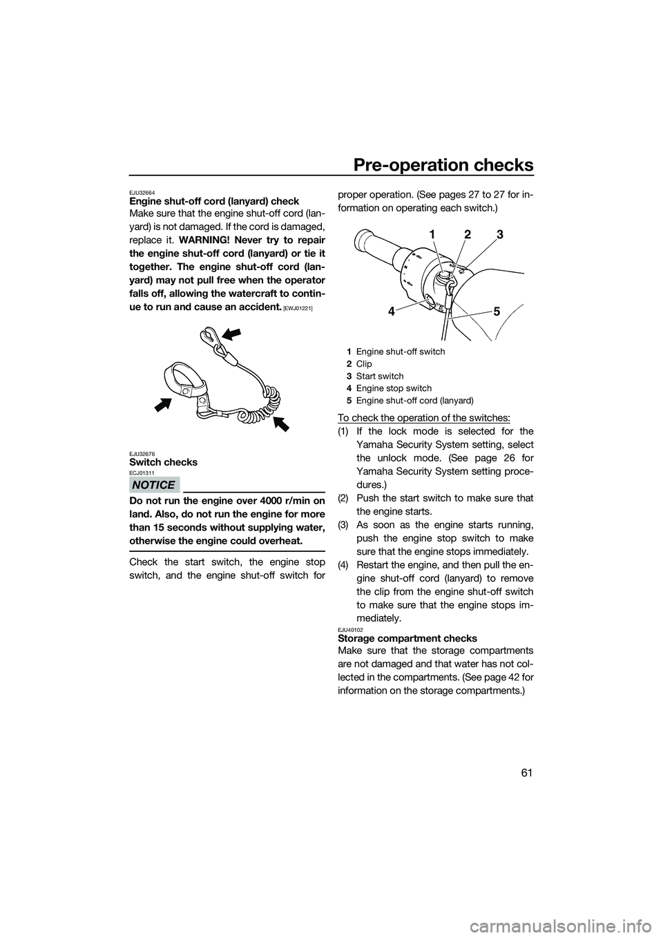
EJU32664Engine shut-off cord (lanyard) check
Make sure that the engine shut-off cord (lan-
yard) is not damaged. If the cord is damaged,
replace it. WARNING! Never try to repair
the engine shut-off cord (lanyard) or tie it
together. The engine shut-off cord (lan-
yard) may not pull free when the operator
falls off, allowing the watercraft to contin-
ue to run and cause an accident.
[EWJ01221]
EJU32676
Switch checks
NOTICE
ECJ01311
Do not run the engine over 4000 r/min on
land. Also, do not run the engine for more
than 15 seconds without supplying water,
otherwise the engine could overheat.
Check the start switch, the engine stop
switch, and the engine shut-off switch for proper operation. (See pages 27 to 27 for in-
formation on operating each switch.)
To check the operation of the switches:
(1) If the lock mode is selected for the
Yamaha Security System setting, selectthe unlock mode. (See page 26 for
Yamaha Security System setting proce- dures.)
(2) Push the start switch to make sure that the engine starts.
(3) As soon as the engine starts running, push the engine stop switch to make
sure that the engine stops immediately.
(4) Restart the engine, and then pull the en- gine shut-off cord (lanyard) to remove
the clip from the engine shut-off switch
to make sure that the engine stops im-
mediately.
EJU40102Storage compartment checks
Make sure that the storage compartments
are not damaged and that water has not col-
lected in the compartments. (See page 42 for
information on the storage compartments.)
1Engine shut-off switch
2 Clip
3 Start switch
4 Engine stop switch
5 Engine shut-off cord (lanyard)
23
1
5
4
UF3L70E0.book Page 61 Thursday, November 7, 2013 9:08 AM
Page 68 of 106
Pre-operation checks
62
EJU41082Fire extinguisher holder, cover, and band
checks
Make sure that the fire extinguisher holder,
cover, and band are not damaged and that
the cover is securely held in place using the
band. (See page 45 for information on the fire
extinguisher holder, cover, and band.)
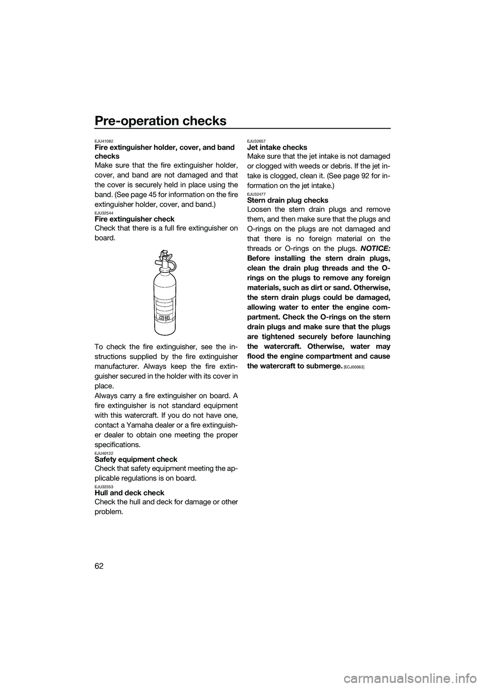
EJU32544Fire extinguisher check
Check that there is a full fire extinguisher on
board.
To check the fire extinguisher, see the in-
structions supplied by the fire extinguisher
manufacturer. Always keep the fire extin-
guisher secured in the holder with its cover in
place.
Always carry a fire extinguisher on board. A
fire extinguisher is not standard equipment
with this watercraft. If you do not have one,
contact a Yamaha dealer or a fire extinguish-
er dealer to obtain one meeting the proper
specifications.
EJU40122Safety equipment check
Check that safety equipment meeting the ap-
plicable regulations is on board.
EJU32353Hull and deck check
Check the hull and deck for damage or other
problem.
EJU32657Jet intake checks
Make sure that the jet intake is not damaged
or clogged with weeds or debris. If the jet in-
take is clogged, clean it. (See page 92 for in-
formation on the jet intake.)
EJU32477Stern drain plug checks
Loosen the stern drain plugs and remove
them, and then make sure that the plugs and
O-rings on the plugs are not damaged and
that there is no foreign material on the
threads or O-rings on the plugs. NOTICE:
Before installing the stern drain plugs,
clean the drain plug threads and the O-
rings on the plugs to remove any foreign
materials, such as dirt or sand. Otherwise,
the stern drain plugs could be damaged,
allowing water to enter the engine com-
partment. Check the O-rings on the stern
drain plugs and make sure that the plugs
are tightened securely before launching
the watercraft. Otherwise, water may
flood the engine compartment and cause
the watercraft to submerge.
[ECJ00363]
UF3L70E0.book Page 62 Thursday, November 7, 2013 9:08 AM
Page 69 of 106
Pre-operation checks
63
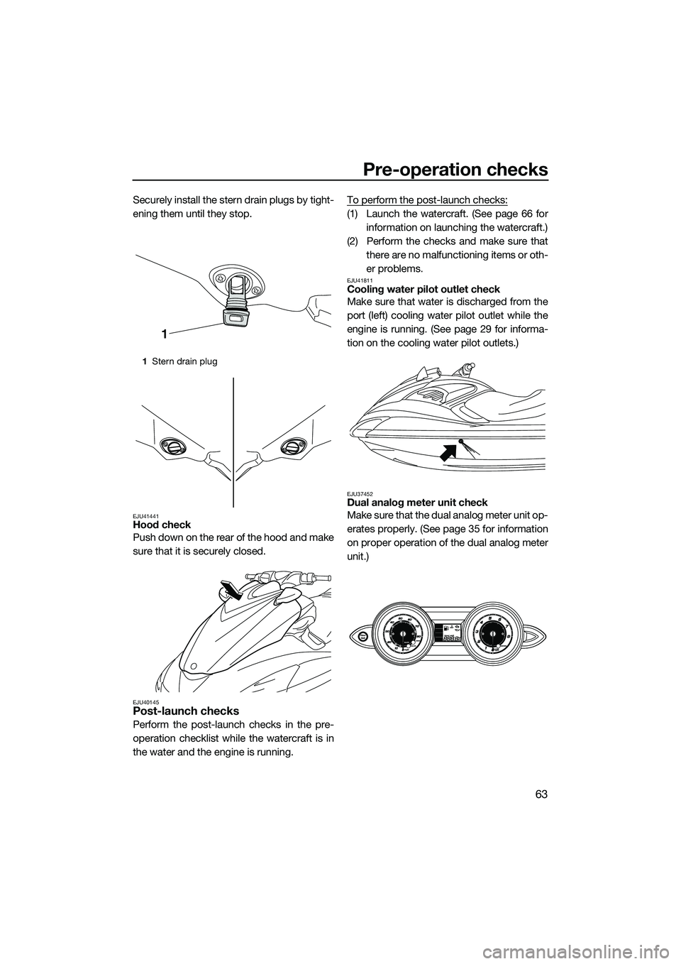
Securely install the stern drain plugs by tight-
ening them until they stop.
EJU41441Hood check
Push down on the rear of the hood and make
sure that it is securely closed.
EJU40145Post-launch checks
Perform the post-launch checks in the pre-
operation checklist while the watercraft is in
the water and the engine is running.To perform the post-launch checks:
(1) Launch the watercraft. (See page 66 for
information on launching the watercraft.)
(2) Perform the checks and make sure that there are no malfunctioning items or oth-
er problems.
EJU41811Cooling water pilot outlet check
Make sure that water is discharged from the
port (left) cooling water pilot outlet while the
engine is running. (See page 29 for informa-
tion on the cooling water pilot outlets.)
EJU37452Dual analog meter unit check
Make sure that the dual analog meter unit op-
erates properly. (See page 35 for information
on proper operation of the dual analog meter
unit.)
1Stern drain plug
1
UF3L70E0.book Page 63 Thursday, November 7, 2013 9:08 AM
Page 70 of 106
Pre-operation checks
64
EJU41331Engine idling speed check
Start the engine and warm it up. Use the ta-
chometer in the dual analog meter unit to
make sure that the engine idling speed is not
significantly above or below the specified
range.Engine idling speed:1250 ±100 r/min
UF3L70E0.book Page 64 Thursday, November 7, 2013 9:08 AM