warning YAMAHA FZR SVHO 2015 Owners Manual
[x] Cancel search | Manufacturer: YAMAHA, Model Year: 2015, Model line: FZR SVHO, Model: YAMAHA FZR SVHO 2015Pages: 104, PDF Size: 5.31 MB
Page 4 of 104
Important manual information
EJU30193
To the owner/operator
Thank you for choosing a Yamaha watercraft.
This owner’s/operator’s manual contains in-
formation you will need for proper operation,
maintenance, and care. If you have any ques-
tions about the operation or maintenance of
your watercraft, please consult a Yamaha
dealer.
This manual is not a course on boating safety
or seamanship. If this is your first watercraft,
or if you are changing to a type of watercraft
you are not familiar with, for your own com-
fort and safety, please ensure that you obtain
proper training or practice before operating
the watercraft by yourself. In addition, a
Yamaha dealer or boating organization will be pleased to recommend local sea schools, or
competent instructors.
In this manual, information of particular im-
portance is distinguished in the following
ways:
This is the safety alert symbol. It is used
to alert you to potential personal injury haz-
ards. Obey all safety messages that follow
this symbol to avoid possible injury or death.
WARNING
EWJ00072
A WARNING indicates a hazardous situa-
tion which, if not avoided, could result in
death or serious injury.
NOTICE
ECJ00092
A NOTICE indicates special precautions
that must be taken to avoid damage to the
watercraft or other property.
TIP:
A TIP provides key information to make pro-
cedures easier or clearer.
EJU40411
Because Yamaha has a policy of continuing
product improvement, this product may not
be exactly as described in this owner’s/oper-
ator’s manual. Specifications are subject to
change without notice.
This manual should be considered a perma-
nent part of this wate rcraft and should remain
with it even if the watercraft is subsequently
sold.
EJU30233
WaveRunner FZR SVHO
OWNER’S/OPERATOR’S MANUAL ©2014 by Yamaha Motor Co., Ltd.
1st Edition, April 2014All rights reserved.
Any reprinting or unauthorized use
without the written permission of Ya m a h a M o t o r C o . , L t d . is expressly prohibited.
Printed in U.S.A.
UF3L71E0.book Page 2 Monday, June 30, 2014 9:06 AM
Page 5 of 104
Table of contents
General and important labels ........... 1Identification numbers .................... 1
Primary Identification (PRI-ID)
number............................................ 1
Craft Identification Number (CIN) ....... 1
Engine serial number.......................... 1
Manufactured date label .................... 2
Model information ........................... 2
Builder’s plate .................................... 2
Important labels .............................. 4
Warning labels.................................... 5
Other labels ........................................ 9
Safety information ........................... 11 Limitations on who may operate the watercraft ............................. 11
Cruising limitations ........................ 12
Operation requirements ................ 13
Recommended equipment ........... 15
Hazard information........................ 16
Watercraft characteristics ............. 16
Safe boating rules ......................... 18
Enjoy your watercraft responsibly ................................. 18
Description....................................... 20 Watercraft glossary ....................... 20
Location of main components ...... 21
Control function operation ............. 25 Watercraft control functions ......... 25
Remote control transmitter .............. 25
Yamaha Security System ................. 26
Engine stop switch .......................... 27
Engine shut-off switch .................... 27
Start switch ..................................... 27
Throttle lever .................................... 28
Steering system ............................... 28
Telescopic steering system.............. 29
Cooling water pilot outlets ............... 29
Water separator................................ 30
Watercraft operation ...................... 31Watercraft operation functions ..... 31
Reverse system ................................ 31
Quick Shift Trim System
(Q.S.T.S.) ....................................... 32
Watercraft operation modes ......... 33
Low RPM Mode ............................... 33
Instrument operation ...................... 35Dual analog meter unit.................. 35
Speedometer.................................... 35
Tachometer ...................................... 35
Information display ........................... 36
Equipment operation ...................... 40Equipment..................................... 40
Seats ................................................ 40
Reboarding grip................................ 41
Reboarding step ............................... 41
Bow eye............................................ 42
Stern eyes ........................................ 42
Storage compartments .................... 42
Fire extinguisher holder and cover ... 45
Operation and handling
requirements ................................... 47Fuel requirements ......................... 47
Fuel................................................... 47
Engine oil requirements ................ 49
Engine oil .......................................... 49
Draining the bilge water ................ 50
Draining the bilge water on land....... 50
Draining the bilge water on water .... 51
Transporting on a trailer................ 52
First-time operation ........................ 53 Engine break-in............................. 53
Pre-operation checks ..................... 54
Pre-operation checklist .................... 54
Pre-operation check points .......... 56
Pre-launch checks ........................... 56
Post-launch checks.......................... 63
UF3L71E0.book Page 1 Monday, June 30, 2014 9:06 AM
Page 11 of 104
General and important labels
5
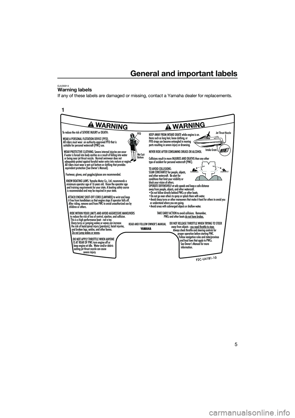
EJU35914Warning labels
If any of these labels are damaged or missing, contact a Yamaha dealer for replacements.
1
UF3L71E0.book Page 5 Monday, June 30, 2014 9:06 AM
Page 13 of 104
General and important labels
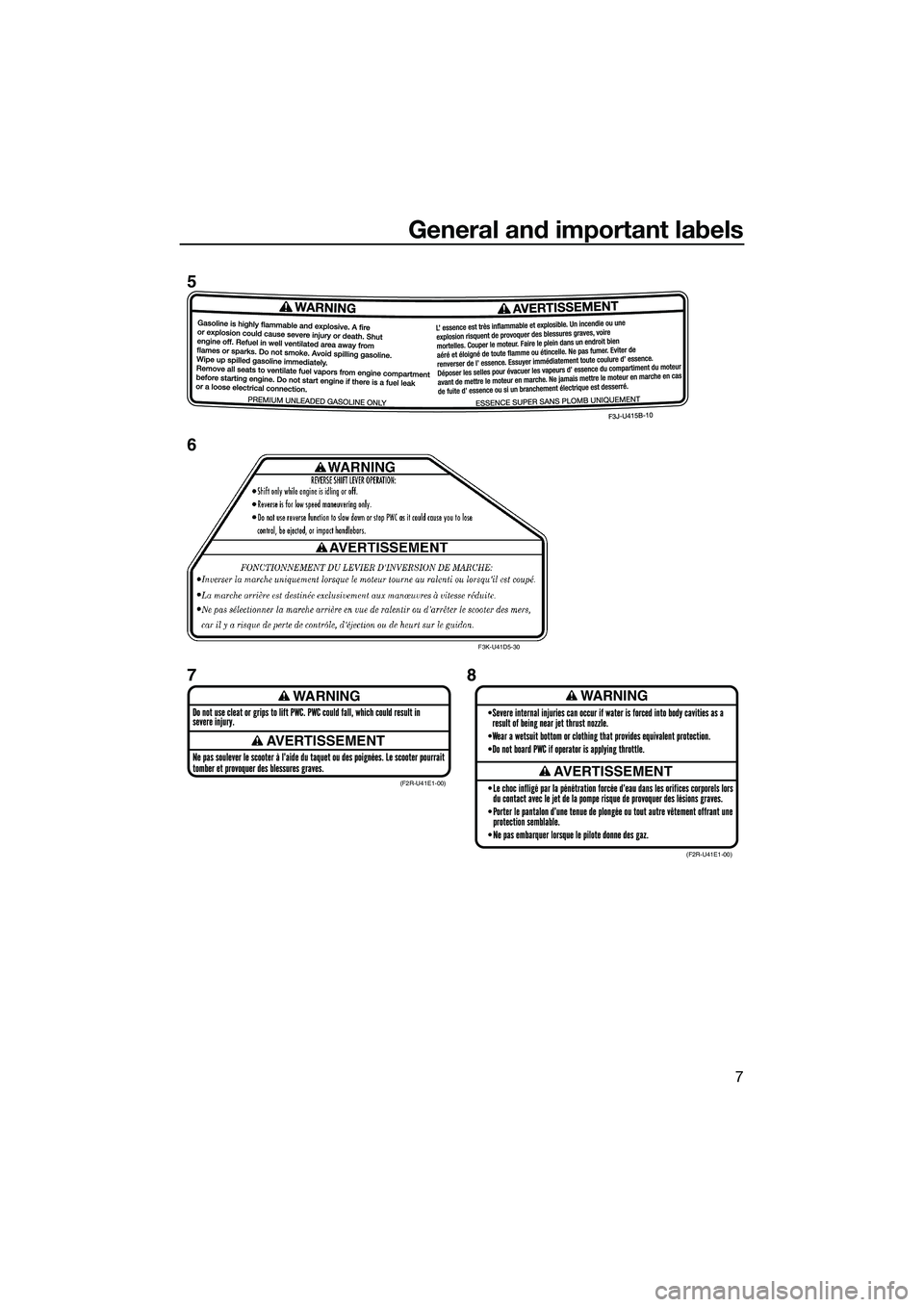
7
WARNING
AVERTISSEMENT
WARNING
AVERTISSEMENT(F2R-U41E1-00)(F2R-U41E1-00)
F3K-U41D5-30
5
6
78
UF3L71E0.book Page 7 Monday, June 30, 2014 9:06 AM
Page 35 of 104
Control function operation
29
in response to handlebar input until you apply
throttle again or you reach trolling speed.
EJU37342Telescopic steering system
The position of the handlebars can be adjust-
ed up or down by operating the lock lever.
The handlebars can be adjusted to three po-
sitions.
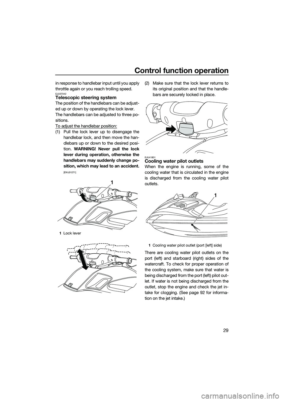
To adjust the handlebar position:
(1) Pull the lock lever up to disengage thehandlebar lock, and then move the han-
dlebars up or down to the desired posi-
tion. WARNING! Never pull the lock
lever during operation, otherwise the
handlebars may suddenly change po-
sition, which may lead to an accident.
[EWJ01271]
(2) Make sure that the lock lever returns to its original position and that the handle-
bars are securely locked in place.
EJU41801Cooling water pilot outlets
When the engine is running, some of the
cooling water that is circulated in the engine
is discharged from the cooling water pilot
outlets.
There are cooling water pilot outlets on the
port (left) and starboard (right) sides of the
watercraft. To check for proper operation of
the cooling system, make sure that water is
being discharged from the port (left) pilot out-
let. If water is not being discharged from the
outlet, stop the engine and check the jet in-
take for clogging. (See page 92 for informa-
tion on the jet intake.)
1Lock lever
1
1Cooling water pilot outlet (port [left] side)
1
UF3L71E0.book Page 29 Monday, June 30, 2014 9:06 AM
Page 37 of 104
Watercraft operation
31
EJU40013
Watercraft operation functions
EJU37183Reverse system
WARNING
EWJ01231
Do not use the reverse function to slow
down or stop the watercraft as it could
cause you to lose control, be ejected, or
impact the handlebars.
Make sure that there are no obstacles or
people behind you before shifting into
reverse.
Do not touch the reverse gate while the
shift lever is being operated, otherwise
you could be pinched.
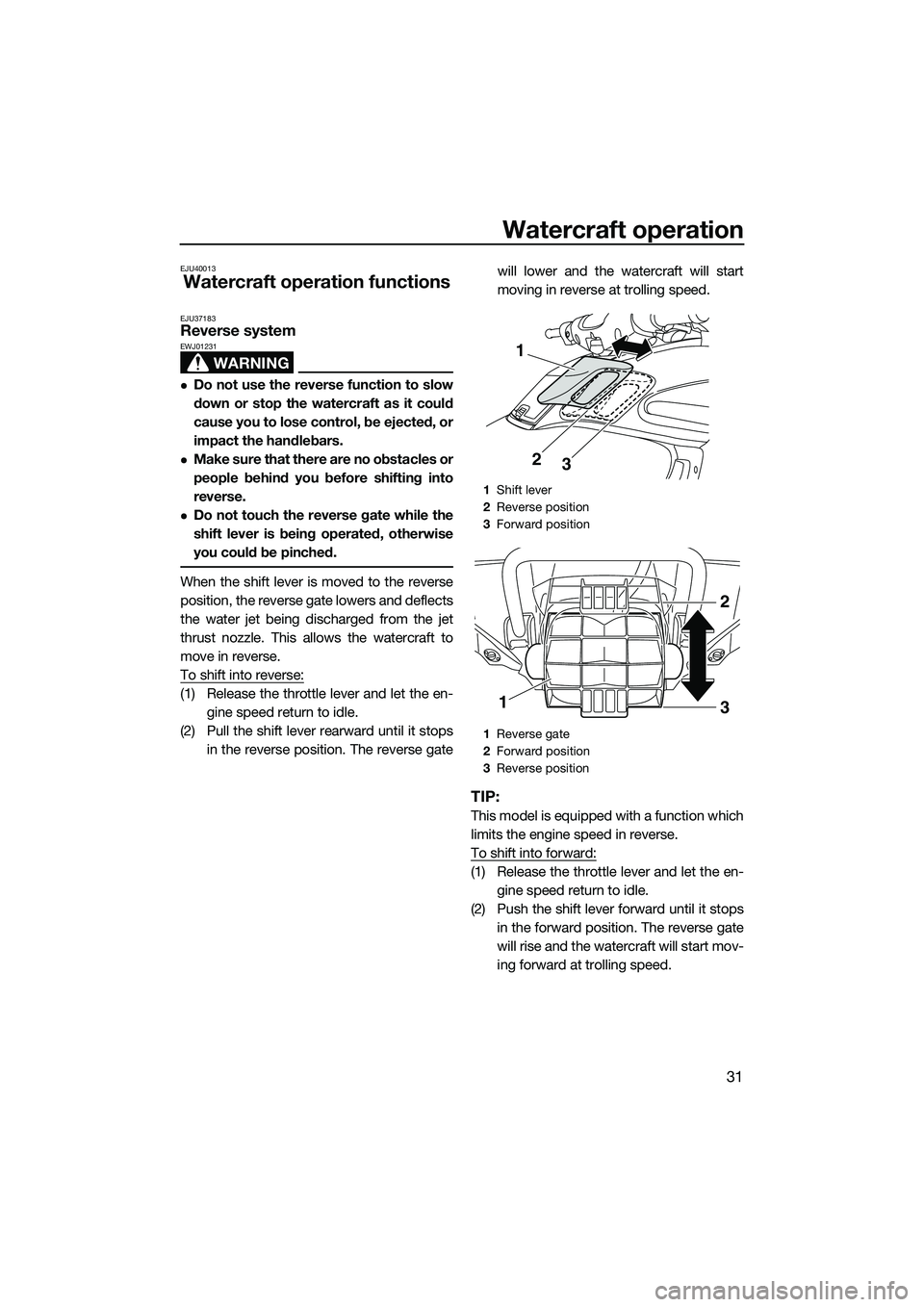
When the shift lever is moved to the reverse
position, the reverse gate lowers and deflects
the water jet being discharged from the jet
thrust nozzle. This allows the watercraft to
move in reverse.
To shift into reverse:
(1) Release the throttle lever and let the en-gine speed return to idle.
(2) Pull the shift lever rearward until it stops in the reverse position. The reverse gate will lower and the watercraft will start
moving in reverse at trolling speed.
TIP:
This model is equipped with a function which
limits the engine speed in reverse.
To shift into forward:
(1) Release the throttle lever and let the en-
gine speed return to idle.
(2) Push the shift lever forward until it stops in the forward position. The reverse gate
will rise and the watercraft will start mov-
ing forward at trolling speed.
1Shift lever
2 Reverse position
3 Forward position
1 Reverse gate
2 Forward position
3 Reverse position
3
2
1
1
2
3
UF3L71E0.book Page 31 Monday, June 30, 2014 9:06 AM
Page 41 of 104
Instrument operation
35
EJU37433
Dual analog meter unit
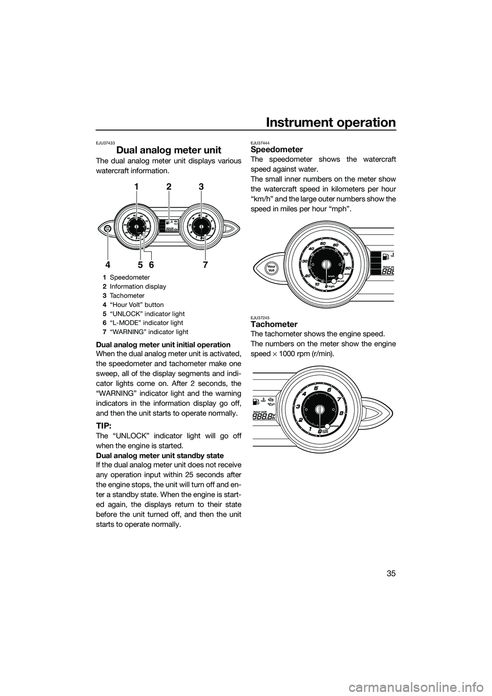
The dual analog meter unit displays various
watercraft information.
Dual analog meter unit initial operation
When the dual analog meter unit is activated,
the speedometer and tachometer make one
sweep, all of the display segments and indi-
cator lights come on. After 2 seconds, the
“WARNING” indicator light and the warning
indicators in the information display go off,
and then the unit starts to operate normally.
TIP:
The “UNLOCK” indicator light will go off
when the engine is started.
Dual analog meter unit standby state
If the dual analog meter unit does not receive
any operation input within 25 seconds after
the engine stops, the unit will turn off and en-
ter a standby state. When the engine is start-
ed again, the displays return to their state
before the unit turned off, and then the unit
starts to operate normally.
EJU37444Speedometer
The speedometer shows the watercraft
speed against water.
The small inner numbers on the meter show
the watercraft speed in kilometers per hour
“km/h” and the large outer numbers show the
speed in miles per hour “mph”.
EJU37245Tachometer
The tachometer shows the engine speed.
The numbers on the meter show the engine
speed × 1000 rpm (r/min).
1 Speedometer
2 Information display
3 Tachometer
4 “Hour Volt” button
5 “UNLOCK” indicator light
6 “L-MODE” indicator light
7 “WARNING” indicator light
123
7
654
UF3L71E0.book Page 35 Monday, June 30, 2014 9:06 AM
Page 42 of 104
Instrument operation
36
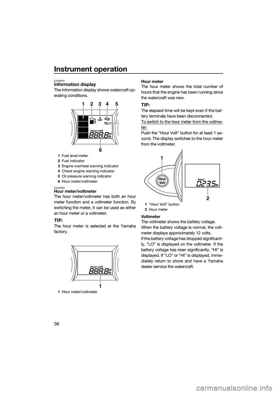
EJU35025Information display
The information display shows watercraft op-
erating conditions.
EJU37265Hour meter/voltmeter
The hour meter/voltmeter has both an hour
meter function and a voltmeter function. By
switching the meter, it can be used as either
an hour meter or a voltmeter.
TIP:
The hour meter is selected at the Yamaha
factory.Hour meter
The hour meter shows the total number of
hours that the engine has been running since
the watercraft was new.
TIP:
The elapsed time will be kept even if the bat-
tery terminals have been disconnected.
To switch to the hour meter from the voltme-
ter:
Push the “Hour Volt” button for at least 1 se-
cond. The display switches to the hour meter
from the voltmeter.
Voltmeter
The voltmeter shows the battery voltage.
When the battery voltage is normal, the volt-
meter displays approximately 12 volts.
If the battery voltage has dropped significant-
ly, “LO” is displayed on the voltmeter. If the
battery voltage has risen significantly, “HI” is
displayed. If “LO” or “HI” is displayed, imme-
diately return to shore and have a Yamaha
dealer service the watercraft.
1
Fuel level meter
2 Fuel indicator
3 Engine overheat warning indicator
4 Check engine warning indicator
5 Oil pressure warning indicator
6 Hour meter/voltmeter
1 Hour meter/voltmeter
12345
6
1
1 “Hour Volt” button
2 Hour meter
1
2
UF3L71E0.book Page 36 Monday, June 30, 2014 9:06 AM
Page 43 of 104
Instrument operation
37
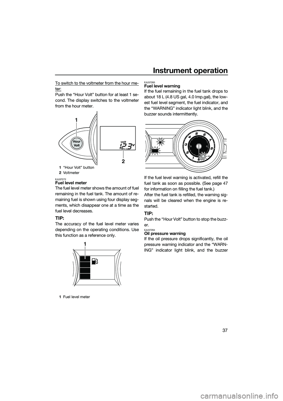
To switch to the voltmeter from the hour me-
ter:
Push the “Hour Volt” button for at least 1 se-
cond. The display switches to the voltmeter
from the hour meter.
EJU37272Fuel level meter
The fuel level meter shows the amount of fuel
remaining in the fuel tank. The amount of re-
maining fuel is shown using four display seg-
ments, which disappear one at a time as the
fuel level decreases.
TIP:
The accuracy of the fuel level meter varies
depending on the operating conditions. Use
this function as a reference only.
EJU37285Fuel level warning
If the fuel remaining in the fuel tank drops to
about 18 L (4.8 US gal, 4.0 Imp.gal), the low-
est fuel level segment, the fuel indicator, and
the “WARNING” indicator light blink, and the
buzzer sounds intermittently.
If the fuel level warning is activated, refill the
fuel tank as soon as possible. (See page 47
for information on filling the fuel tank.)
After the fuel tank is refilled, the warning sig-
nals will be cleared when the engine is re-
started.
TIP:
Push the “Hour Volt” button to stop the buzz-
er.
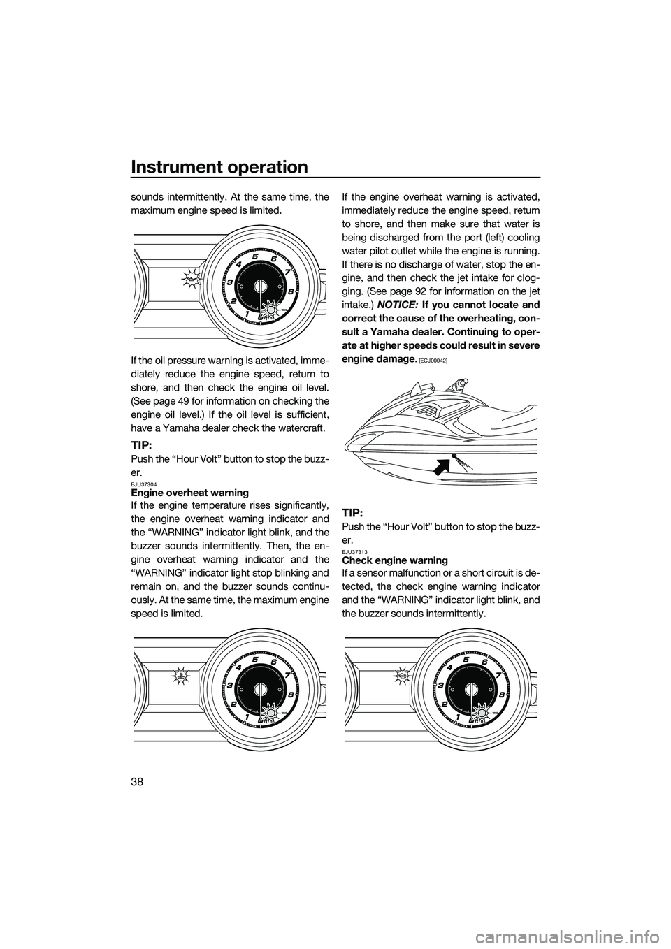
EJU37294Oil pressure warning
If the oil pressure drops significantly, the oil
pressure warning indicator and the “WARN-
ING” indicator light blink, and the buzzer
1“Hour Volt” button
2 Vo l t m et e r
1 Fuel level meter
1
2
1
UF3L71E0.book Page 37 Monday, June 30, 2014 9:06 AM
Page 44 of 104
Instrument operation
38
sounds intermittently. At the same time, the
maximum engine speed is limited.
If the oil pressure warning is activated, imme-
diately reduce the engine speed, return to
shore, and then check the engine oil level.
(See page 49 for information on checking the
engine oil level.) If the oil level is sufficient,
have a Yamaha dealer check the watercraft.
TIP:
Push the “Hour Volt” button to stop the buzz-
er.
EJU37304Engine overheat warning
If the engine temperature rises significantly,
the engine overheat warning indicator and
the “WARNING” indicator light blink, and the
buzzer sounds intermittently. Then, the en-
gine overheat warning indicator and the
“WARNING” indicator light stop blinking and
remain on, and the buzzer sounds continu-
ously. At the same time, the maximum engine
speed is limited.If the engine overheat warning is activated,
immediately reduce the engine speed, return
to shore, and then make sure that water is
being discharged from the port (left) cooling
water pilot outlet while the engine is running.
If there is no discharge of water, stop the en-
gine, and then check the jet intake for clog-
ging. (See page 92 for information on the jet
intake.)
NOTICE: If you cannot locate and
correct the cause of the overheating, con-
sult a Yamaha dealer. Continuing to oper-
ate at higher speeds could result in severe
engine damage.
[ECJ00042]
TIP:
Push the “Hour Volt” button to stop the buzz-
er.
EJU37313Check engine warning
If a sensor malfunction or a short circuit is de-
tected, the check engine warning indicator
and the “WARNING” indicator light blink, and
the buzzer sounds intermittently.
UF3L71E0.book Page 38 Monday, June 30, 2014 9:06 AM