fuse YAMAHA GRIZZLY 125 2009 Owners Manual
[x] Cancel search | Manufacturer: YAMAHA, Model Year: 2009, Model line: GRIZZLY 125, Model: YAMAHA GRIZZLY 125 2009Pages: 130, PDF Size: 4.08 MB
Page 9 of 130
Parking on a slope .................................... 6-5
Accessories and loading ........................... 6-6
RIDING YOUR ATV ...................................... 7-1
GETTING TO KNOW YOUR ATV.............. 7-2
RIDE WITH CARE AND GOOD
JUDGEMENT ........................................... 7-2
BE CAREFUL WHERE YOU RIDE ............ 7-9
TURNING YOUR ATV ............................. 7-13
CLIMBING UPHILL .................................. 7-14
RIDING DOWNHILL................................. 7-17
CROSSING A SLOPE.............................. 7-18
CROSSING THROUGH SHALLOW
WATER .................................................. 7-19
RIDING OVER ROUGH TERRAIN .......... 7-21
SLIDING AND SKIDDING ........................ 7-21
WHAT TO DO IF... ................................... 7-22
WHAT TO DO... ....................................... 7-22
PERIODIC MAINTENANCE AND MINOR
REPAIR .......................................................... 8-1
Owner’s manual and tool kit ...................... 8-1
Periodic maintenance chart for the
emission control system .......................... 8-3
General maintenance and lubrication
chart ........................................................ 8-5
Checking the spark plug ............................ 8-8
Engine oil .................................................. 8-9
Transmission oil ...................................... 8-12Cleaning the engine and V-belt case air
filter elements ........................................ 8-15
V-belt case drain plug .............................. 8-21
Adjusting the carburetor ........................... 8-22
Adjusting the engine idling speed ............ 8-22
Adjusting the throttle cable free play ........ 8-23
Valve clearance ....................................... 8-24
Checking the front and rear brake
shoes ..................................................... 8-24
Adjusting the front brake lever free
play ........................................................ 8-25
Adjusting the rear brake lever free
play ........................................................ 8-30
Drive chain slack ...................................... 8-32
Lubricating the drive chain ....................... 8-34
Checking and lubricating the cables ........ 8-35
Checking and lubricating the front and
rear brake levers .................................... 8-36
Checking the wheel hub bearings ............ 8-36
Lubricating the upper and lower arm
pivots ..................................................... 8-36
Lubricating the front knuckle pivots ......... 8-37
Lubricating the steering shaft ................... 8-38
Battery ..................................................... 8-38
Replacing the fuse ................................... 8-41
Replacing a headlight bulb ...................... 8-42
Adjusting a headlight beam ..................... 8-44
Replacing the tail/brake light bulb ............ 8-44
Removing a wheel ................................... 8-45
Page 109 of 130
8-41
1
2
3
4
5
6
78
9
10
11
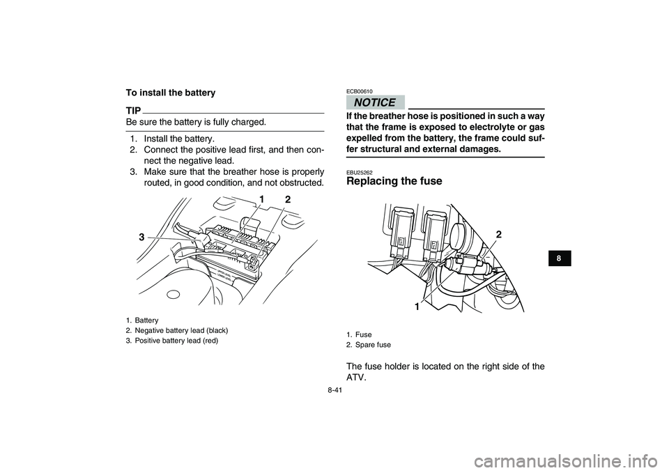
To install the battery
TIP
Be sure the battery is fully charged.
1. Install the battery.
2. Connect the positive lead first, and then con-
nect the negative lead.
3. Make sure that the breather hose is properly
routed, in good condition, and not obstructed.
NOTICE
ECB00610
If the breather hose is positioned in such a way
that the frame is exposed to electrolyte or gas
expelled from the battery, the frame could suf-
fer structural and external damages.
EBU25262
Replacing the fuse
The fuse holder is located on the right side of the
ATV.
1. Battery
2. Negative battery lead (black)
3. Positive battery lead (red)
1
2
3
1. Fuse
2. Spare fuse
12
Page 110 of 130
8-42
1
2
3
4
5
6
78
9
10
11
If the fuse is blown, replace it as follows.
1. Turn the key to “OFF” and turn off all electrical
circuits.
NOTICE
ECB00640
To prevent accidental short-circuiting, turn off
the main switch when checking or replacing a
fuse.
2. Remove the blown fuse, and then install a
new fuse of the specified amperage.
WARNING
EWB02171
Always use a fuse of the specified rating, and
never use a substitute object in place of the
proper fuse. An improper fuse or a substitute
object can cause damage to the electrical sys-
tem, which could lead to a fire.
3. Turn the key to “ON” and turn on the electrical
circuits to check if the devices operate.
4. If the fuse immediately blows again, have a
Yamaha dealer check the electrical system.
EBU25480
Replacing a headlight bulb
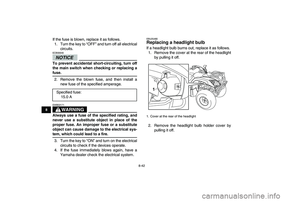
If a headlight bulb burns out, replace it as follows.
1. Remove the cover at the rear of the headlight
by pulling it off.
2. Remove the headlight bulb holder cover by
pulling it off. Specified fuse:
15.0 A
1. Cover at the rear of the headlight
1
Page 123 of 130
10-4
1
2
3
4
5
6
7
8
910
11
Front suspension:
Type:
Swing axle
Spring/shock absorber type:
Coil spring/oil damper
Wheel travel:
70 mm (2.8 in)
Rear suspension:
Type:
Swingarm
Spring/shock absorber type:
Coil spring/oil damper
Wheel travel:
80 mm (3.1 in)
Electrical system:
Ignition system:
DC. CDI
Charging system:
AC magneto
Battery:
Model:
12N12C-4A-2
Voltage, capacity:
12 V, 12.0 Ah
Headlight:
Bulb type:
Krypton bulb
Bulb voltage, wattage
×
quantity:
Headlight:
12 V, 30.0/30.0 W
×
2Tail/brake light:
12 V, 5.0/21.0 W
×
1
Neutral indicator light:
12 V, 1.7 W
×
1
Reverse indicator light:
12 V, 1.7 W
×
1
Fuses:
Main fuse:
15.0 A
Page 127 of 130
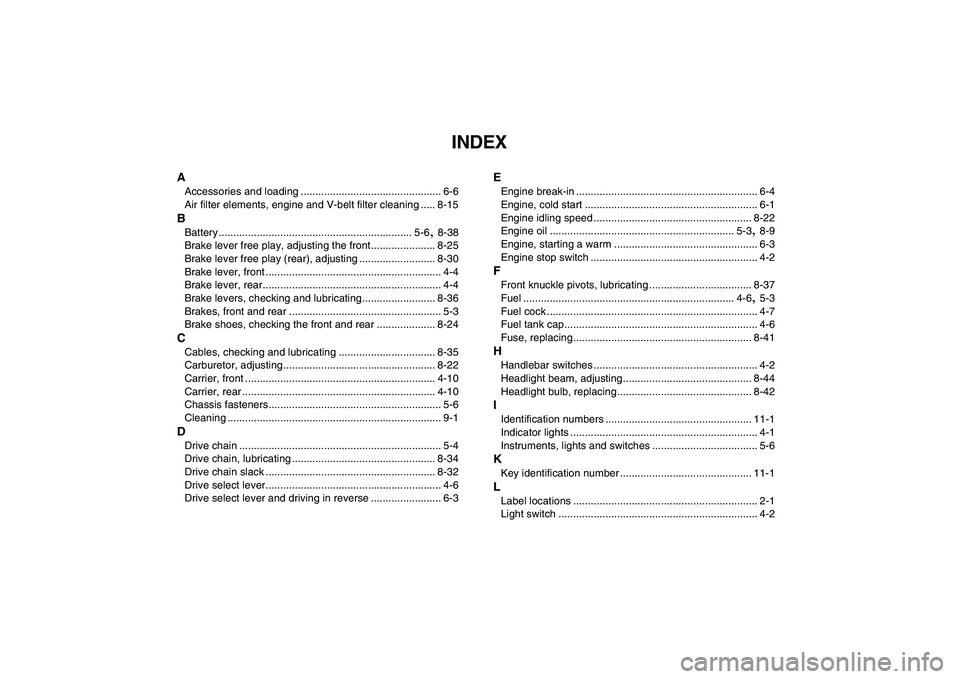
INDEX
A
Accessories and loading ................................................ 6-6
Air filter elements, engine and V-belt filter cleaning ..... 8-15
B
Battery .................................................................. 5-6
,
8-38
Brake lever free play, adjusting the front...................... 8-25
Brake lever free play (rear), adjusting .......................... 8-30
Brake lever, front ............................................................ 4-4
Brake lever, rear............................................................. 4-4
Brake levers, checking and lubricating......................... 8-36
Brakes, front and rear .................................................... 5-3
Brake shoes, checking the front and rear .................... 8-24
C
Cables, checking and lubricating ................................. 8-35
Carburetor, adjusting.................................................... 8-22
Carrier, front ................................................................. 4-10
Carrier, rear .................................................................. 4-10
Chassis fasteners........................................................... 5-6
Cleaning ......................................................................... 9-1
D
Drive chain ..................................................................... 5-4
Drive chain, lubricating ................................................. 8-34
Drive chain slack .......................................................... 8-32
Drive select lever............................................................ 4-6
Drive select lever and driving in reverse ........................ 6-3
E
Engine break-in .............................................................. 6-4
Engine, cold start ........................................................... 6-1
Engine idling speed ...................................................... 8-22
Engine oil ............................................................... 5-3
,
8-9
Engine, starting a warm ................................................. 6-3
Engine stop switch ......................................................... 4-2
F
Front knuckle pivots, lubricating ................................... 8-37
Fuel ........................................................................ 4-6
,
5-3
Fuel cock ........................................................................ 4-7
Fuel tank cap.................................................................. 4-6
Fuse, replacing............................................................. 8-41
H
Handlebar switches ........................................................ 4-2
Headlight beam, adjusting............................................ 8-44
Headlight bulb, replacing.............................................. 8-42
I
Identification numbers .................................................. 11-1
Indicator lights ................................................................ 4-1
Instruments, lights and switches .................................... 5-6
K
Key identification number ............................................. 11-1
L
Label locations ............................................................... 2-1
Light switch .................................................................... 4-2