maintenance YAMAHA GRIZZLY 350 2015 Owner's Manual
[x] Cancel search | Manufacturer: YAMAHA, Model Year: 2015, Model line: GRIZZLY 350, Model: YAMAHA GRIZZLY 350 2015Pages: 146, PDF Size: 3.35 MB
Page 109 of 146
8-26
8
TIPIf the specified idling speed cannot be obtained as
described above, have a Yamaha dealer make the
adjustment. EBU24048Adjusting the throttle lever free playThe throttle lever free play should be checked and,
if necessary, adjusted at the intervals specified in
the periodic maintenance and lubrication chart.The throttle lever free play should measure 3.0–5.0
mm (0.12–0.20 in) as shown. Periodically check
the throttle lever free play and, if necessary, adjust
it as follows.
TIPThe engine idling speed must be checked, and
adjusted if necessary, before adjusting the throttle
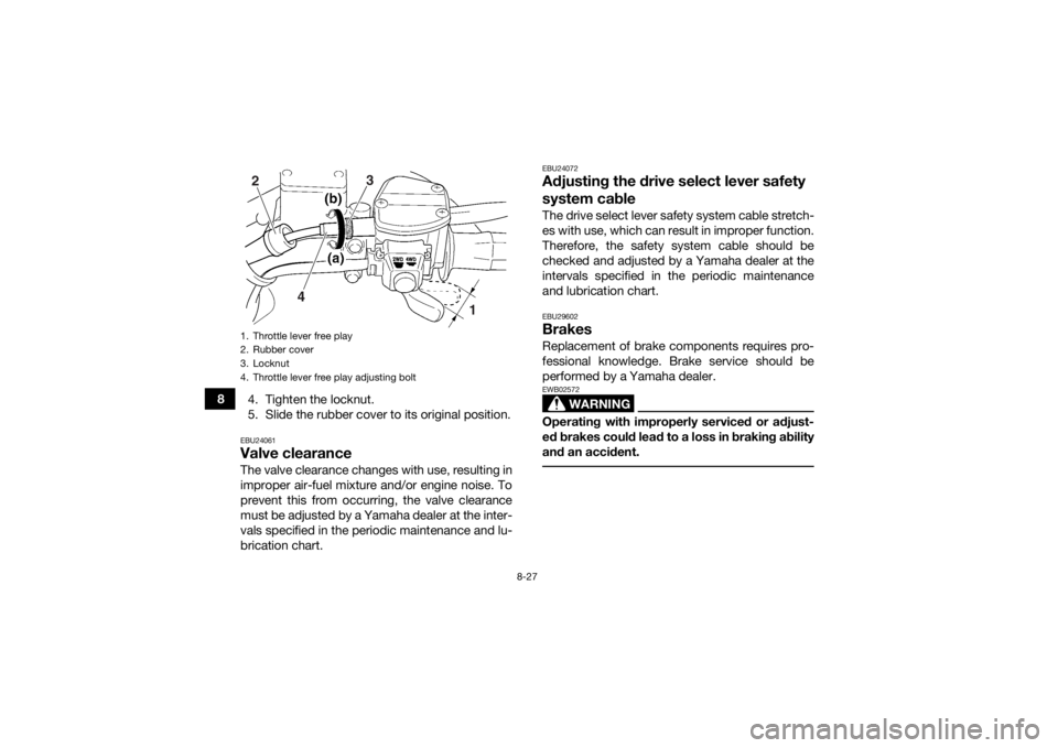
lever free play. 1. Slide the rubber cover back.
2. Loosen the locknut.
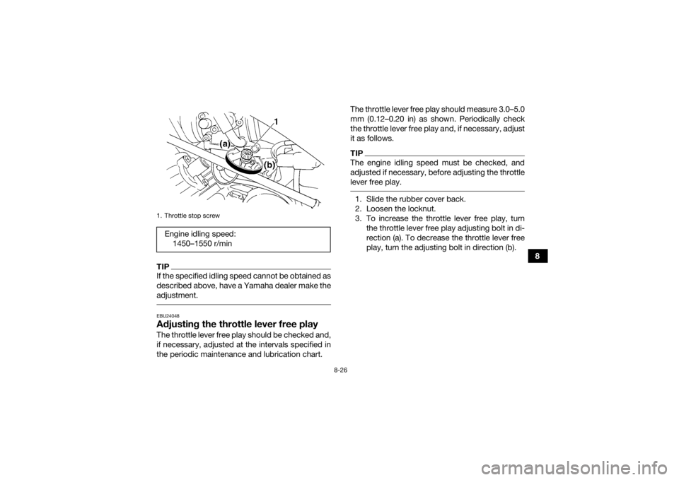
3. To increase the throttle lever free play, turn
the throttle lever free play adjusting bolt in di-
rection (a). To decrease the throttle lever free
play, turn the adjusting bolt in direction (b).
1. Throttle stop screwEngine idling speed:1450–1550 r/min
U1NS63E0.book Page 26 Monday, March 10, 2014 9:05 AM
Page 110 of 146
8-27
84. Tighten the locknut.
5. Slide the rubber cover to its original position.
EBU24061Valve clearanceThe valve clearance changes with use, resulting in
improper air-fuel mixture and/or engine noise. To
prevent this from occurring, the valve clearance
must be adjusted by a Yamaha dealer at the inter-
vals specified in the periodic maintenance and lu-
brication chart.
EBU24072Adjusting the drive select lever safety
system cableThe drive select lever safety system cable stretch-
es with use, which can result in improper function.
Therefore, the safety system cable should be
checked and adjusted by a Yamaha dealer at the
intervals specified in the periodic maintenance
and lubrication chart.EBU29602BrakesReplacement of brake components requires pro-
fessional knowledge. Brake service should be
performed by a Yamaha dealer.
WARNING
EWB02572Operating with improperly serviced or adjust-
ed brakes could lead to a loss in braking ability
and an accident.
1. Throttle lever free play
2. Rubber cover
3. Locknut
4. Throttle lever free play adjusting bolt2
4 3
1
U1NS63E0.book Page 27 Monday, March 10, 2014 9:05 AM
Page 111 of 146

8-28
8
EBU24121Checking the front brake pads and rear
brake shoesThe front brake pads and the rear brake shoes
must be checked for wear at the intervals speci-
fied in the periodic maintenance and lubrication
chart.EBU24172Front brake pads
Check each front brake pad for damage and mea-
sure the lining thickness. If a brake pad is dam-
aged or if the lining thickness is less than 1.0 mm
(0.04 in), have a Yamaha dealer replace the brake
pads as a set.
TIPThe wheels need to be removed to check the
brake pads. (See page 8-46.) EBU24181Rear brake shoes
The rear brake is provided with a wear indicator,
which allows you to check the brake shoe wear
without having to disassemble the brake. To
check the brake shoe wear, check the position of
the wear indicator while applying the brake. If a1. Brake pad
2. Lining thickness
2
1
U1NS63E0.book Page 28 Monday, March 10, 2014 9:05 AM
Page 112 of 146

8-29
8brake shoe has worn to the point that the wear in-
dicator reaches the wear limit line or mark, have a
Yamaha dealer replace the brake shoes as a set.
EBU29843Checking the brake fluid levelBefore riding, check that the brake fluid is above
the minimum level mark. Check the brake fluid lev-
el with the top of the reservoir level. Replenish the
brake fluid if necessary.
WARNING
EWB02721Improper maintenance can result in loss of
braking ability. Observe these precautions:
Insufficient brake fluid may allow air to enter
the brake system, reducing braking perfor-
mance.
Clean the filler cap before removing. Use
only DOT 4 brake fluid from a sealed contain-
er.
1. Wear limit line
2. Wear indicator
1
2
1. Minimum level markSpecified brake fluid: DOT 4
1
U1NS63E0.book Page 29 Monday, March 10, 2014 9:05 AM
Page 113 of 146
8-30
8
Use only the specified brake fluid; otherwise,
the rubber seals may deteriorate, causing
leakage.
Refill with the same type of brake fluid. Add-
ing a brake fluid other than DOT 4 may result
in a harmful chemical reaction.
Be careful that water does not enter the
brake fluid reservoir when refilling. Water will
significantly lower the boiling point of the flu-
id and may result in vapor lock.
NOTICEECB01161Brake fluid may damage painted surfaces or
plastic parts. Always clean up spilled fluid im-
mediately. As the brake pads wear, it is normal for the brake
fluid level to gradually go down. A low brake fluid
level may indicate worn brake pads and/or brake
system leakage; therefore, be sure to check the
brake pads for wear and the brake system for
leakage. If the brake fluid level goes down sud-
denly, have a Yamaha dealer check the cause be-
fore further riding.
EBU24283Changing the brake fluidHave a Yamaha dealer change the brake fluid at
the intervals specified in the periodic maintenance
and lubrication chart. In addition, have the oil seals
of the brake master cylinder and calipers as well
as the brake hoses replaced at the intervals listed
below or whenever they are damaged or leaking.
Oil seals: Replace every two years.
Brake hoses: Replace every four years.EBU24395Checking the front brake lever free
playThe brake lever free play must be checked at the
intervals specified in the periodic maintenance
and lubrication chart. The brake lever should have
no free play as shown. If there is free play, have a
Yamaha dealer check the brake system.
U1NS63E0.book Page 30 Monday, March 10, 2014 9:05 AM
Page 114 of 146

8-31
8
EBU30691Adjusting the brake pedal height, and
the brake pedal and rear brake lever
free playThe brake pedal height, brake pedal free play, and
rear brake lever free play must be checked and, if
necessary, adjusted at the intervals specified in
the periodic maintenance and lubrication chart.TIPAlways perform this maintenance completely in
the following order whenever adjusting the rear
brake.
Before adjusting the brake pedal and brake le-
ver free play, check the rear brake shoes for
wear.
Checking and adjusting the brake pedal height
The top of the brake pedal should be positioned
72.0–82.0 mm (2.83–3.23 in) above the footboard
bracket.
Check and adjust the brake pedal height as fol-
lows.
1. Remove the footboard by removing the bolts and nuts.
1. No brake lever free play
1. Distance between brake pedal and footboard bracket
1
U1NS63E0.book Page 31 Monday, March 10, 2014 9:05 AM
Page 119 of 146

8-36
8
EBU24231Axle bootsThe axle boots must be checked for damage at
the intervals specified in the periodic maintenance
and lubrication chart. Check the axle boots for
tears or damage. If any damage is found, have
them replaced by a Yamaha dealer.EBU29882Brake light switchesThe brake light, which is activated by the brake
pedal and brake levers, should come on just be-
fore braking takes effect.The rear brake light switch for the brake pedal can
be adjusted as follows, but the other brake light
switches should be adjusted by a Yamaha dealer.
Turn the rear brake light switch adjusting nut while
holding the brake light switch in place. To make
the brake light come on earlier, turn the adjusting
nut in direction (a). To make the brake light come
on later, turn the adjusting nut in direction (b).
EBU24905Checking and lubricating the cablesThe operation and the condition of all control ca-
bles should be checked before each ride, and the
cables and cable ends should be lubricated if nec-
1. Axle boot (each side)
1
1
1. Rear brake light switch
2. Rear brake light switch adjusting nut
U1NS63E0.book Page 36 Monday, March 10, 2014 9:05 AM
Page 121 of 146

8-38
8
Rear brake lever
EBU28872Checking and lubricating the brake
pedalThe operation of the brake pedal should be
checked before each ride, and the pedal pivot
should be lubricated if necessary.
EBU24964Checking the wheel hub bearingsThe front and rear wheel hub bearings must be
checked at the intervals specified in the periodic
maintenance and lubrication chart. If there is play
in a wheel hub or if a wheel does not turn smooth-
ly, have a Yamaha dealer check the wheel hub
bearings.
Recommended lubricant:
Lithium-soap-based grease
U1NS63E0.book Page 38 Monday, March 10, 2014 9:05 AM
Page 122 of 146

8-39
8
EBU25093Lubricating the steering shaftThe steering shaft must be lubricated by a
Yamaha dealer at the intervals specified in the pe- riodic maintenance and lubrication chart.TIPFor parts equipped with a grease nipple, use a
grease gun.
EBU2918ABatteryThe battery is located under the seat. (See page
4-14.)
This model is equipped with a VRLA (Valve Regu-
lated Lead Acid) battery. There is no need to
check the electrolyte or to add distilled water.
However, the battery lead connections need to be
checked and, if necessary, tightened.
WARNING
EWB02161Battery electrolyte is poisonous and danger-
ous, as it contains sulfuric acid, which can cau-
se severe burns. Avoid contact with skin, eyes
or clothing. Always shield your eyes when
working near batteries.
Antidote:
EXTERNAL: Flush with water.
INTERNAL: Drink large quantities of water or
milk. Follow with milk of magnesia, beaten egg
or vegetable oil. Call a physician immediately.
EYES: Flush with water for 15 minutes and get
prompt medical attention.
Batteries produce explosive gases. Keep
sparks, flame, cigarettes or other sources of
ignition away. Ventilate when charging or using
in an enclosed space.
Recommended lubricant:
Lithium-soap-based grease
U1NS63E0.book Page 39 Monday, March 10, 2014 9:05 AM
Page 144 of 146

12-2
12
MMain switch .................................................................... 4-1
Maintenance and lubrication chart ................................8-5
Maintenance chart, emission control system ................ 8-3
Model label ................................................................... 11-1NNeutral indicator light .....................................................4-2OOil temperature warning light ......................................... 4-3
On-Command four-wheel-drive switch ......................... 4-6
Owner’s manual and tool kit .......................................... 8-2PParking ........................................................................... 6-5
Parking brake ................................................................. 4-9
Parking on a slope ......................................................... 6-5
Part locations ................................................................. 3-1RRear brake, adjusting the pedal height, and the pedal and lever free play ..................................................... 8-31
Reverse indicator light ................................................... 4-2
Riding your ATV ............................................................. 7-1SSafety information .......................................................... 2-1
Seat .............................................................................. 4-14
Shock absorber assemblies, adjusting the front .........4-17
Shock absorber assembly, adjusting the rear ............. 4-18
Spark arrester, cleaning ............................................... 8-22
Spark plug, checking .....................................................8-9
Specifications ............................................................... 10-1
Speed limiter .................................................................. 4-7
Speedometer ................................................................. 4-3 Starter (choke) .............................................................. 4-14
Start switch .................................................................... 4-5
Steering shaft, lubricating ............................................ 8-39
Storage .......................................................................... 9-2
Storage compartment .................................................. 4-15
TTail/brake light bulb, replacing ..................................... 8-46
Throttle lever .......................................................... 4-6, 5-4
Throttle lever free play, adjusting ................................. 8-26
Tires ............................................................................... 5-4
Troubleshooting ........................................................... 8-48
Troubleshooting chart .................................................. 8-49VValve clearance ............................................................ 8-27
V-belt case drain plug .................................................. 8-24
V-belt cooling duct check hose ................................... 8-24
Vehicle identification number ....................................... 11-1WWheel hub bearings, checking ..................................... 8-38
Wheel, installing ........................................................... 8-46
Wheel, removing .......................................................... 8-46
U1NS63E0.book Page 2 Monday, March 10, 2014 9:05 AM