warning lights YAMAHA GRIZZLY 350 2015 Owners Manual
[x] Cancel search | Manufacturer: YAMAHA, Model Year: 2015, Model line: GRIZZLY 350, Model: YAMAHA GRIZZLY 350 2015Pages: 146, PDF Size: 3.35 MB
Page 8 of 146

EBU17421
TABLE OF CONTENTS
LOCATION OF THE WARNING AND
SPECIFICATION LABELS .............................. 1-1
SAFETY INFORMATION ................................ 2-1
DESCRIPTION................................................ 3-1Left view ...................................................... 3-1
Right view.................................................... 3-1
Controls and instruments............................ 3-2
INSTRUMENT AND CONTROL
FUNCTIONS ................................................... 4-1 Main switch ................................................. 4-1
Indicator lights and warning light ................ 4-2
Speedometer .............................................. 4-3
Handlebar switches .................................... 4-5
Throttle lever ............................................... 4-6
Speed limiter ............................................... 4-7
Front brake lever ......................................... 4-8
Brake pedal and rear brake lever ................ 4-8
Parking brake .............................................. 4-9
Drive select lever ....................................... 4-10
Fuel tank cap............................................. 4-10
Fuel ........................................................... 4-11 Fuel cock .................................................. 4-12
Starter (choke) ......................................... 4-14
Seat .......................................................... 4-14
Storage compartment............................... 4-15
Front carrier .............................................. 4-16
Rear carrier ............................................... 4-16
Adjusting the front shock absorber
assemblies .............................................. 4-17
Adjusting the rear shock absorber assembly ................................................ 4-18
PRE-OPERATION CHECKS .......................... 5-1 Fuel ............................................................. 5-3
Engine oil .................................................... 5-3
Final gear oil ............................................... 5-3
Differential gear oil ...................................... 5-3
Front and rear brakes ................................. 5-3
Throttle lever ............................................... 5-4
Tires ............................................................ 5-4
Chassis fasteners ....................................... 5-6
Instruments, lights and switches ................ 5-6
OPERATION .................................................. 6-1 Starting a cold engine................................. 6-1U1NS63E0.book Page 1 Monday, March 10, 2014 9:05 AM
Page 29 of 146

4-2
4
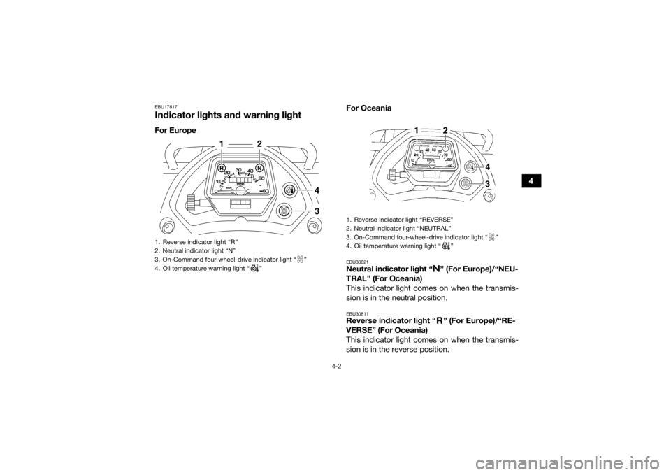
EBU17817Indicator lights and warning lightFor EuropeFor Oceania
EBU30821Neutral indicator light “ ” (For Europe)/“NEU-
TRAL” (For Oceania)
This indicator light comes on when the transmis-
sion is in the neutral position.EBU30811Reverse indicator light “ ” (For Europe)/“RE-
VERSE” (For Oceania)
This indicator light comes on when the transmis-
sion is in the reverse position.
1. Reverse indicator light “R”
2. Neutral indicator light “N”
3. On-Command four-wheel-drive indicator light “ ”
4. Oil temperature warning light “ ”
43
1
2
1. Reverse indicator light “REVERSE”
2. Neutral indicator light “NEUTRAL”
3. On-Command four-wheel-drive indicator light “ ”
4. Oil temperature warning light “ ”
U1NS63E0.book Page 2 Monday, March 10, 2014 9:05 AM
Page 38 of 146

4-11
4
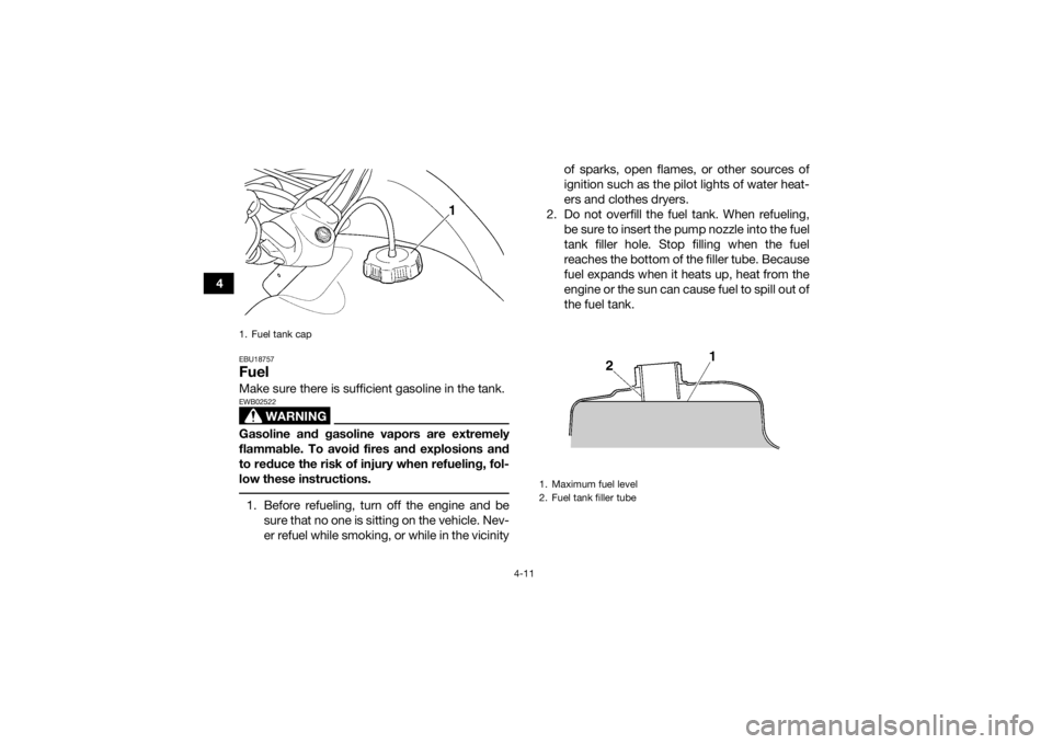
EBU18757FuelMake sure there is sufficient gasoline in the tank.
WARNING
EWB02522Gasoline and gasoline vapors are extremely
flammable. To avoid fires and explosions and
to reduce the risk of injury when refueling, fol-
low these instructions. 1. Before refueling, turn off the engine and besure that no one is sitting on the vehicle. Nev-
er refuel while smoking, or while in the vicinity of sparks, open flames, or other sources of
ignition such as the pilot lights of water heat-
ers and clothes dryers.
2. Do not overfill the fuel tank. When refueling, be sure to insert the pump nozzle into the fuel
tank filler hole. Stop filling when the fuel
reaches the bottom of the filler tube. Because
fuel expands when it heats up, heat from the
engine or the sun can cause fuel to spill out of
the fuel tank.1. Fuel tank cap
1. Maximum fuel level
2. Fuel tank filler tube
U1NS63E0.book Page 11 Monday, March 10, 2014 9:05 AM
Page 131 of 146

8-48
8
EBU25721TroubleshootingAlthough Yamaha ATVs receive a thorough in-
spection before shipment from the factory, trouble
may occur during operation. Any problem in the
fuel, compression, or ignition systems, for exam-
ple, can cause poor starting and loss of power.
The following troubleshooting chart represents a
quick and easy procedure for checking these vital
systems yourself. However, should your ATV re-
quire any repair, take it to a Yamaha dealer, whose
skilled technicians have the necessary tools, ex-
perience, and know-how to service the ATV prop-
erly.
Use only genuine Yamaha replacement parts. Im-
itation parts may look like Yamaha parts, but they
are often inferior, have a shorter service life and
can lead to expensive repair bills.
WARNING
EWB02281Do not smoke when checking the fuel system.
Fuel can ignite or explode, causing severe inju-
ry or property damage. Make sure there are no
open flames or sparks in the area, including pi-
lot lights from water heaters or furnaces. U1NS63E0.book Page 48 Monday, March 10, 2014 9:05 AM
Page 143 of 146

12-1
12
INDEX
AAccessories and loading ................................................ 6-6
Air filter element, cleaning ........................................... 8-19
Axle boots .................................................................... 8-36BBattery ......................................................................... 8-39
Brake fluid, changing ................................................... 8-30
Brake fluid level, checking ........................................... 8-29
Brake lever free play, checking the front ..................... 8-30
Brake lever, front ........................................................... 4-8
Brake levers, checking and lubricating ........................ 8-37
Brake light switches ..................................................... 8-36
Brake pads and shoes, checking ................................ 8-28
Brake pedal and rear brake lever ................................... 4-8
Brake pedal, checking and lubricating ........................ 8-38
Brakes .......................................................................... 8-27
Brakes, front and rear .................................................... 5-3CCables, checking and lubricating ................................ 8-36
Carburetor, adjusting ................................................... 8-25
Carrier, front ................................................................. 4-16
Carrier, rear .................................................................. 4-16
Chassis fasteners .......................................................... 5-6
Cleaning ......................................................................... 9-1DDifferential gear oil ......................................................... 5-3
Differential gear oil, changing ...................................... 8-18
Drive select lever ......................................................... 4-10
Drive select lever and driving in reverse ........................ 6-3Drive select lever safety system cable, adjusting ........ 8-27
EEngine break-in .............................................................. 6-4
Engine, cold start ........................................................... 6-1
Engine idling speed ..................................................... 8-25
Engine oil ....................................................................... 5-3
Engine oil and oil filter cartridge .................................. 8-11
Engine, starting a warm ................................................. 6-3
Engine stop switch ........................................................ 4-5FFinal gear oil ......................................................... 5-3, 8-15
Four-wheel-drive indicator light ..................................... 4-3
Fuel ....................................................................... 4-11, 5-3
Fuel cock ..................................................................... 4-12
Fuel tank cap ............................................................... 4-10
Fuses, replacing .......................................................... 8-42HHandlebar switches ....................................................... 4-5
Headlight beam, adjusting ........................................... 8-45
Headlight bulb, replacing ............................................. 8-44
Horn switch .................................................................... 4-5IIdentification numbers ................................................. 11-1
Indicator lights and warning light ................................... 4-2
Instruments, lights and switches ................................... 5-6LLabel locations ............................................................... 1-1
Light switch ................................................................... 4-5
U1NS63E0.book Page 1 Monday, March 10, 2014 9:05 AM