headlight bulb YAMAHA GRIZZLY 350 2017 Owners Manual
[x] Cancel search | Manufacturer: YAMAHA, Model Year: 2017, Model line: GRIZZLY 350, Model: YAMAHA GRIZZLY 350 2017Pages: 140, PDF Size: 3.23 MB
Page 10 of 140

Checking and lubricating the cables......... 8-35
Checking and lubricating the front and rear brake levers ..................................... 8-35
Checking and lubricating the brake pedal ....................................................... 8-36
Checking the wheel hub bearings............. 8-36
Lubricating the steering shaft ................... 8-37
Battery....................................................... 8-37
Replacing a fuse ....................................... 8-40
Replacing a headlight bulb ....................... 8-42
Adjusting a headlight beam ...................... 8-43
Replacing the tail/brake light bulb ............ 8-44
Removing a wheel ..................................... 8-44
Installing a wheel....................................... 8-44
Troubleshooting ........................................ 8-46
Troubleshooting chart ............................... 8-47
CLEANING AND STORAGE ........................... 9-1 Cleaning ...................................................... 9-1
Storage........................................................ 9-2
SPECIFICATIONS ........................................ 10-1
CONSUMER INFORMATION ....................... 11-1 Identification numbers .............................. 11-1
INDEX ........................................................... 12-1
UB1463E0.book Page 3 Thursday, August 4, 2016 2:12 PM
Page 121 of 140

8-42
8
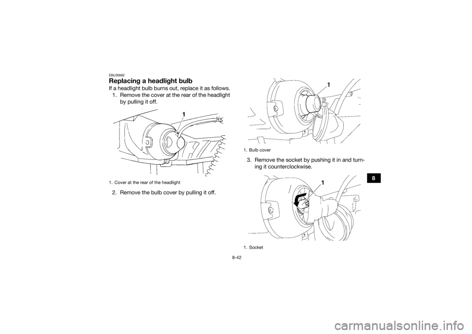
EBU30662Replacing a headlight bulbIf a headlight bulb burns out, replace it as follows.1. Remove the cover at the rear of the headlight by pulling it off.
2. Remove the bulb cover by pulling it off. 3. Remove the socket by pushing it in and turn-
ing it counterclockwise.1. Cover at the rear of the headlight
1. Bulb cover
1. Socket
1
UB1463E0.book Page 42 Thursday, August 4, 2016 2:12 PM
Page 122 of 140

8-43
84. Remove the burnt-out bulb.
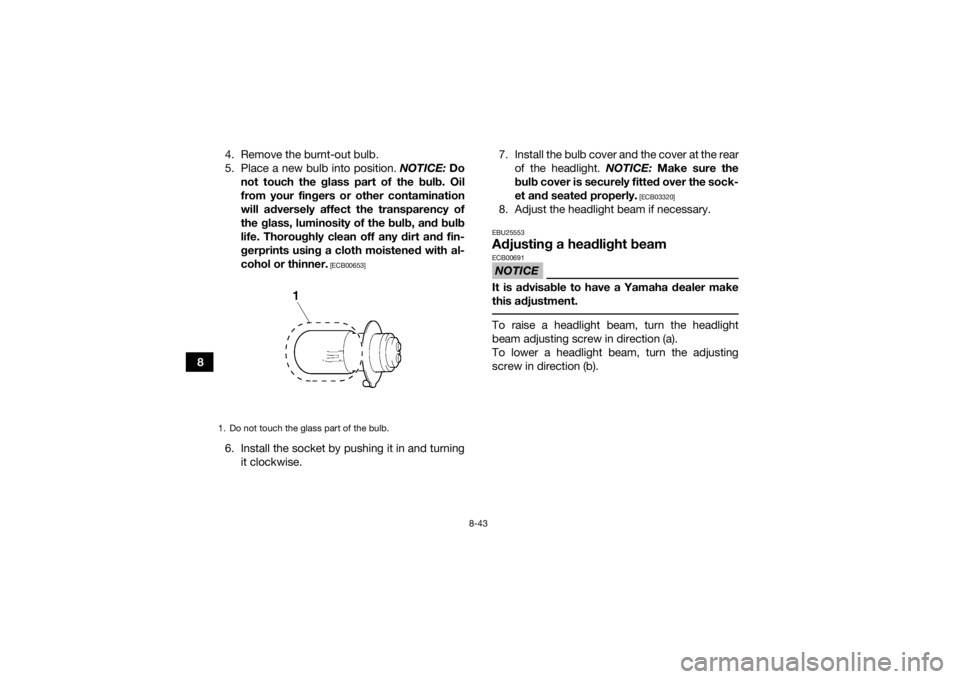
5. Place a new bulb into position.
NOTICE: Do
not touch the glass part of the bulb. Oil
from your fingers or other contamination
will adversely affect the transparency of
the glass, luminosity of the bulb, and bulb
life. Thoroughly clean off any dirt and fin-
gerprints using a cloth moistened with al-
cohol or thinner.
[ECB00653]
6. Install the socket by pushing it in and turning it clockwise. 7. Install the bulb cover and the cover at the rear
of the headlight. NOTICE: Make sure the
bulb cover is securely fitted over the sock-
et and seated properly.
[ECB03320]
8. Adjust the headlight beam if necessary.EBU25553Adjusting a headlight beamNOTICEECB00691It is advisable to have a Yamaha dealer make
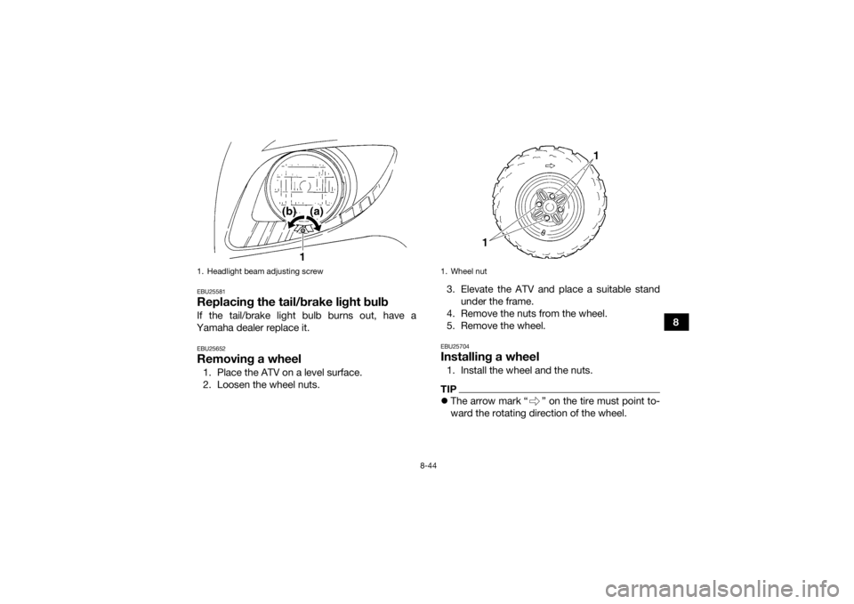
this adjustment. To raise a headlight beam, turn the headlight
beam adjusting screw in direction (a).
To lower a headlight beam, turn the adjusting
screw in direction (b).
1. Do not touch the glass part of the bulb.UB1463E0.book Page 43 Thursday, August 4, 2016 2:12 PM
Page 123 of 140

8-44
8
EBU25581Replacing the tail/brake light bulbIf the tail/brake light bulb burns out, have a
Yamaha dealer replace it.EBU25652Removing a wheel1. Place the ATV on a level surface.
2. Loosen the wheel nuts. 3. Elevate the ATV and place a suitable stand
under the frame.
4. Remove the nuts from the wheel.
5. Remove the wheel.
EBU25704Installing a wheel1. Install the wheel and the nuts.TIP The arrow mark “ ” on the tire must point to-
ward the rotating direction of the wheel.
1. Headlight beam adjusting screw
1. Wheel nut
UB1463E0.book Page 44 Thursday, August 4, 2016 2:12 PM
Page 133 of 140

10-4
10
Operation:Left hand and right foot operationFront suspension:Type:
Double wishbone
Spring/shock absorber type: Coil spring/oil damper
Wheel travel: 160 mm (6.3 in)Rear suspension:Type:Swingarm
Spring/shock absorber type: Coil spring/oil damper
Wheel travel:
180 mm (7.1 in)Electrical system:Ignition system:DC CDI
Charging system:
AC magnetoBattery:Model:YTX14AH
Voltage, capacity:
12 V, 12.0 AhHeadlight(s):Bulb type:Krypton bulb
Bulb voltage, wattage × quantity:Headlight:
12 V, 30.0/30.0 W × 2
Tail/brake light:
12 V, 5.0/21.0 W × 1
Meter lighting: 14 V, 3.0 W × 1
Neutral indicator light: 12 V, 1.7 W × 1
Reverse indicator light:
12 V, 1.7 W × 1
Oil temperature warning light: 12 V, 1.7 W × 1Fuses:Main fuse:
30.0 A
Headlight fuse: 15.0 A
Signaling system fuse: 10.0 A
Ignition fuse:
15.0 A
Auxiliary DC jack fuse: 10.0 AEBU30402For Europe only
The figures quoted are emission levels and are not
necessarily safe working levels. Whilst there is a
correlation between the emission and exposure
UB1463E0.book Page 4 Thursday, August 4, 2016 2:12 PM
Page 137 of 140

12-1
12
INDEX
AAccessories and loading ................................................ 6-6
Air filter element, cleaning ........................................... 8-18BBattery ......................................................................... 8-37
Brake fluid, changing ................................................... 8-29
Brake fluid level, checking ........................................... 8-27
Brake lever free play, checking the front ..................... 8-29
Brake lever, front ........................................................... 4-5
Brake levers, checking and lubricating ........................ 8-35
Brake light switches ..................................................... 8-34
Brake pads and shoes, checking ................................ 8-26
Brake pedal and rear brake lever ................................... 4-6
Brake pedal, checking and lubricating ........................ 8-36
Brakes .......................................................................... 8-26
Brakes, front and rear .................................................... 5-3CCables, checking and lubricating ................................ 8-35
Carburetor, adjusting ................................................... 8-23
Carrier, front ................................................................. 4-14
Carrier, rear .................................................................. 4-14
Chassis fasteners .......................................................... 5-6
Cleaning ......................................................................... 9-1DDrive select lever ........................................................... 4-7
Drive select lever and driving in reverse ........................ 6-3
Drive select lever safety system cable, adjusting ........ 8-26EEngine break-in .............................................................. 6-4Engine, cold start ........................................................... 6-1
Engine idling speed ..................................................... 8-23
Engine oil ....................................................................... 5-3
Engine oil and oil filter cartridge .................................. 8-11
Engine, starting a warm ................................................. 6-3
Engine stop switch ........................................................ 4-3
FFinal gear oil ......................................................... 5-3, 8-15
Fuel ......................................................................... 4-8, 5-3
Fuel cock ..................................................................... 4-10
Fuel tank cap ................................................................. 4-8
Fuses, replacing .......................................................... 8-40HHandlebar switches ....................................................... 4-3
Headlight beam, adjusting ........................................... 8-43
Headlight bulb, replacing ............................................. 8-42
Horn switch .................................................................... 4-4IIdentification numbers ................................................. 11-1
Indicator lights and warning light ................................... 4-2
Instruments, lights and switches ................................... 5-6LLabel locations ............................................................... 1-1
Light switch ................................................................... 4-4MMain switch .................................................................... 4-1
Maintenance and lubrication chart ................................ 8-5
Maintenance chart, emission control system ................ 8-3
Model label .................................................................. 11-1
UB1463E0.book Page 1 Thursday, August 4, 2016 2:12 PM