fuel YAMAHA GRIZZLY 550 2013 Owners Manual
[x] Cancel search | Manufacturer: YAMAHA, Model Year: 2013, Model line: GRIZZLY 550, Model: YAMAHA GRIZZLY 550 2013Pages: 174, PDF Size: 4.21 MB
Page 9 of 174

EBU17420
TABLE OF CONTENTS
LOCATION OF THE WARNING AND
SPECIFICATION LABELS ............................ 1-1
SAFETY INFORMATION .............................. 2-1
DESCRIPTION .............................................. 3-1Left view ...................................................... 3-1
Right view.................................................... 3-1
Controls and instruments ............................ 3-2
INSTRUMENT AND CONTROL
FUNCTIONS .................................................. 4-1 Main switch ................................................ 4-1
Indicator lights and warning lights .............. 4-2
Multi-function display .................................. 4-5
Handlebar switches .................................... 4-7
Throttle lever ............................................ 4-13
Speed limiter ............................................ 4-13
Front brake lever ...................................... 4-14
Brake pedal and rear brake lever ............. 4-14
Drive select lever ...................................... 4-15
Fuel tank cap ............................................ 4-15
Fuel .......................................................... 4-16
Seat .......................................................... 4-18 Storage compartments .............................4-18
Front carrier ..............................................4-21
Rear carrier ...............................................4-21
Adjusting the front and rear shock
absorber assemblies ...............................4-21
Auxiliary DC jack .......................................4-23
PRE-OPERATION CHECKS ..........................5-1 Fuel .............................................................5-3
Engine oil ....................................................5-3
Final gear oil ...............................................5-3
Differential gear oil ......................................5-3
Coolant .......................................................5-3
Front and rear brakes .................................5-3
Throttle lever ...............................................5-4
Tires ............................................................5-4
Chassis fasteners .......................................5-7
Instruments, lights and switches .................5-7
OPERATION...................................................6-1 Starting the engine ......................................6-1
Operating the drive select lever and driving in reverse ......................................6-2
Engine break-in ...........................................6-4U1HS61E0.book Page 1 Wednesday, May 23, 2012 5:24 PM
Page 16 of 174
1-5
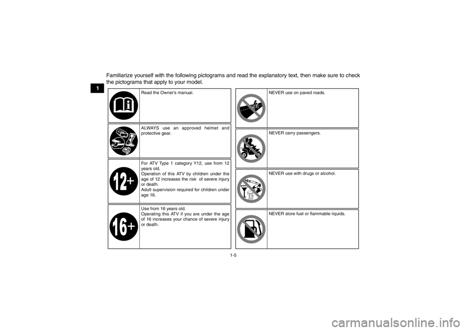
1Familiarize yourself with the following pictograms and read the explanatory text, then make sure to check
the pictograms that apply to your model.
Read the Owner’s manual.
ALWAYS use an approved helmet and
protective gear.
For ATV Type 1 category Y12, use from 12
years old.
Operation of this ATV by children under the
age of 12 increases the risk of severe injury
or death.
Adult supervision required for children under
age 16.
Use from 16 years old.
Operating this ATV if you are under the age
of 16 increases your chance of severe injury
or death. NEVER use on paved roads.
NEVER carry passengers.
NEVER use with drugs or alcohol.
NEVER store fuel or flammable liquids.
U1HS61E0.book Page 5 Wednesday, May 23, 2012 5:24 PM
Page 26 of 174

2-4
2In the event of an accident
1. If serious injuries are incurred, you may be safer staying next to your vehicle; it may
shield you from oncoming riders. Depending
on your injuries and position in the trail; you
must make a judgment call as to whether you
should move to a position off the trail. If you
have sustained head, neck, or back injuries,
or cannot feel your limbs, you should not
move. Keep your helmet on and remain mo-
tionless. Lie down next to your vehicle and
wait for help.
2. If less serious injuries are incurred and you can walk, then move to a position off the trail.
Check yourself for injuries and apply first aid
as needed.
3. If your injuries are light, when safe to do so, move your vehicle off the trail to avoid colli-
sions with oncoming riders. Check for injuries
and apply first aid as necessary. If you can
physically operate your vehicle, inspect your
vehicle. If the vehicle is in safe operating con-
dition and you can safely operate it, restart it
and ride gently back to camp or other known
location where you can receive medical atten- tion. If necessary, contact your riding party or
local authorities to let them know where you
are and what has happened.
In the event of a breakdown 1. If your vehicle will not restart or is not in safe operating condition, turn off the main switch
and engine stop switch. If the breakdown oc-
curs at twilight or night, leave the main switch
on so that your lights may warn other riders of
your stopped vehicle.
2. Get out of danger. Check for oncoming vehi- cles and when safe, push your vehicle to the
side of the trail or even off the main trail to
avoid any possible collisions with oncoming
riders. If you cannot move your vehicle by
yourself, when safe, walk to the nearest van-
tage point and signal an oncoming rider to
help you push your vehicle to a safe place off
the trail.
3. Inspect your vehicle for any immediate haz- ardous conditions. The most obvious hazard-
ous conditions are leaking fuel and
ungrounded or broken wiring. Visually check
for broken wiring and leaking fuel. Leaking
fuel can be confirmed by the odor of gasoline.
U1HS61E0.book Page 4 Wednesday, May 23, 2012 5:24 PM
Page 27 of 174

2-5
2
4. Once immediate safety hazards are con-
firmed not to exist, you may remove your hel-
met to more closely inspect your vehicle.
Check for external signs of wear, broken
parts, fluid leaks, cracks in the frame, suspen-
sion damage, wheel damage, and so on. Fuel,
oil, and coolant usually give off a noticeable
odor.
5. If your vehicle will not restart or if it is unsafe to ride, then turn off all vehicle systems (en-
gine stop switch, main switch, and fuel cock),
and then signal or go for help.
Aftermarket Parts, Accessories, and Modifica-
tions
While you may find aftermarket products similar in
design and quality to genuine Yamaha accesso-
ries, recognize that some aftermarket accessories
or modifications are not suitable because of poten-
tial safety hazards to you or others. Installing after-
market products or having other modifications
performed to your vehicle that change any of the
vehicle’s design or operation characteristics can
put you and others at greater risk of serious injury
or death. You are responsible for injuries related to changes in the vehicle. Keep the following guide-
lines in mind, as well as those provided under
“Loading” when mounting accessories.
●Never install accessories that would impair the
performance of your ATV. Carefully inspect the
accessory before using it to make sure that it
does not in any way reduce ground clearance,
limit suspension travel, steering travel or control
operation.●Accessories fitted to the ATV can create instabil-
ity due to improper weight distribution.●Bulky or large accessories may seriously affect
the stability of the ATV.●Certain accessories can displace the operator
from his or her normal riding position. This im-
proper position limits the freedom of movement
of the operator and may limit control ability,
therefore, such accessories are not recom-
mended.●Use caution when adding electrical accessories.
If electrical accessories exceed the capacity of
the ATV’s electrical system, an electric failure
could result, which could cause a dangerous
loss of lights or engine power.
U1HS61E0.book Page 5 Wednesday, May 23, 2012 5:24 PM
Page 29 of 174
3-1
3
EBU17680
DESCRIPTION
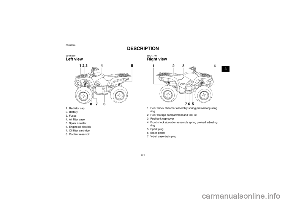
EBU17690Left view
EBU17700Right view
1. Radiator cap
2. Battery
3. Fuses
4. Air filter case
5. Spark arrester
6. Engine oil dipstick
7. Oil filter cartridge
8. Coolant reservoir
5
1. Rear shock absorber assembly spring preload adjusting ring
2. Rear storage compartment and tool kit
3. Fuel tank cap cover
4. Front shock absorber assembly spring preload adjusting ring
5. Spark plug
6. Brake pedal
7. V-belt case drain plug
U1HS61E0.book Page 1 Wednesday, May 23, 2012 5:24 PM
Page 35 of 174
4-5
4
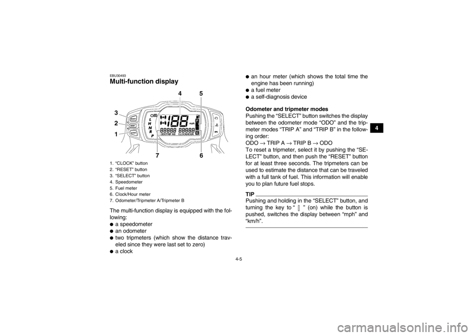
EBU30493Multi-function display The multi-function display is equipped with the fol-
lowing:●a speedometer●an odometer●two tripmeters (which show the distance trav-
eled since they were last set to zero)●a clock
●an hour meter (which shows the total time the
engine has been running)●a fuel meter●a self-diagnosis device
Odometer and tripmeter modes
Pushing the “SELECT” button switches the display
between the odometer mode “ODO” and the trip-
meter modes “TRIP A” and “TRIP B” in the follow-
ing order:
ODO → TRIP A → TRIP B → ODO
To reset a tripmeter, select it by pushing the “SE-
LECT” button, and then push the “RESET” button
for at least three seconds. The tripmeters can be
used to estimate the distance that can be traveled
with a full tank of fuel. This information will enable
you to plan future fuel stops.TIPPushing and holding in the “SELECT” button, and
turning the key to “ ” (on) while the button is
pushed, switches the display between “mph” and
“km/h”.
1. “CLOCK” button
2. “RESET” button
3. “SELECT” button
4. Speedometer
5. Fuel meter
6. Clock/Hour meter
7. Odometer/Tripmeter A/Tripmeter BU1HS61E0.book Page 5 Wednesday, May 23, 2012 5:24 PM
Page 36 of 174
4-6
4Clock mode
Pushing the “CLOCK” button switches the display
between the clock mode “CLOCK” and the hour
meter mode “HOUR” in the following order:
CLOCK
→ HOUR → CLOCK
To set the clock
1. Set the display to the clock mode.
2. Push the “SELECT” button and “RESET” but- ton together for at least three seconds.
3. When the hour digits start flashing, push the “RESET” button to set the hours.
4. Push the “SELECT” button, and the minute digits will start flashing.
5. Push the “RESET” button to set the minutes.
6. Push the “SELECT” button and then release it to start the clock.
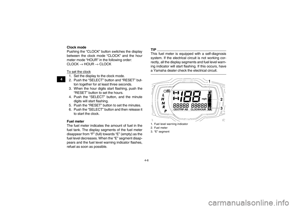
Fuel meter
The fuel meter indicates the amount of fuel in the
fuel tank. The display segments of the fuel meter
disappear from “F” (full) towards “E” (empty) as the
fuel level decreases. When the “E” segment disap-
pears and the fuel level warning indicator flashes,
refuel as soon as possible.
TIPThis fuel meter is equipped with a self-diagnosis
system. If the electrical circuit is not working cor-
rectly, all the display segments and fuel level warn-
ing indicator will start flashing. If this occurs, have
a Yamaha dealer check the electrical circuit.1. Fuel level warning indicator
2. Fuel meter
3. “E” segment
U1HS61E0.book Page 6 Wednesday, May 23, 2012 5:24 PM
Page 45 of 174
4-15
4
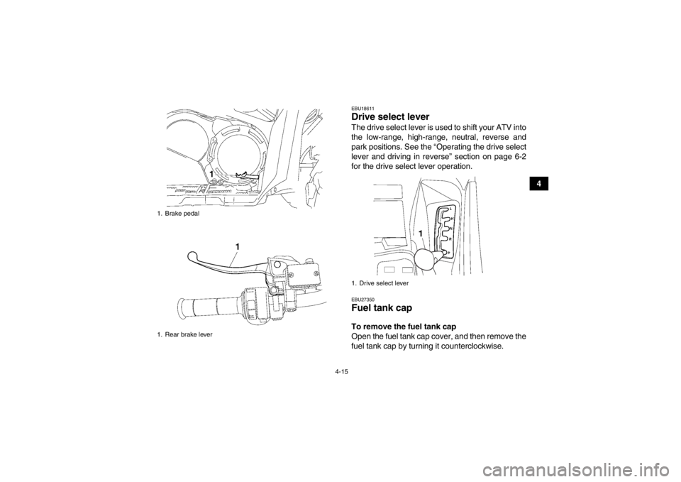
EBU18611Drive select lever The drive select lever is used to shift your ATV into
the low-range, high-range, neutral, reverse and
park positions. See the “Operating the drive select
lever and driving in reverse” section on page 6-2
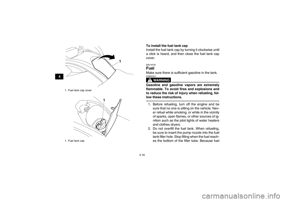
for the drive select lever operation.EBU27350Fuel tank cap To remove the fuel tank cap
Open the fuel tank cap cover, and then remove the
fuel tank cap by turning it counterclockwise.
1. Brake pedal
1. Rear brake lever
1. Drive select lever
U1HS61E0.book Page 15 Wednesday, May 23, 2012 5:24 PM
Page 46 of 174
4-16
4To install the fuel tank cap
Install the fuel tank cap by turning it clockwise until
a click is heard, and then close the fuel tank cap
cover.
EBU18755Fuel Make sure there is sufficient gasoline in the tank.
WARNING
EWB02521Gasoline and gasoline vapors are extremely
flammable. To avoid fires and explosions and
to reduce the risk of injury when refueling, fol-
low these instructions.1. Before refueling, turn off the engine and be
sure that no one is sitting on the vehicle. Nev-
er refuel while smoking, or while in the vicinity
of sparks, open flames, or other sources of ig-
nition such as the pilot lights of water heaters
and clothes dryers.
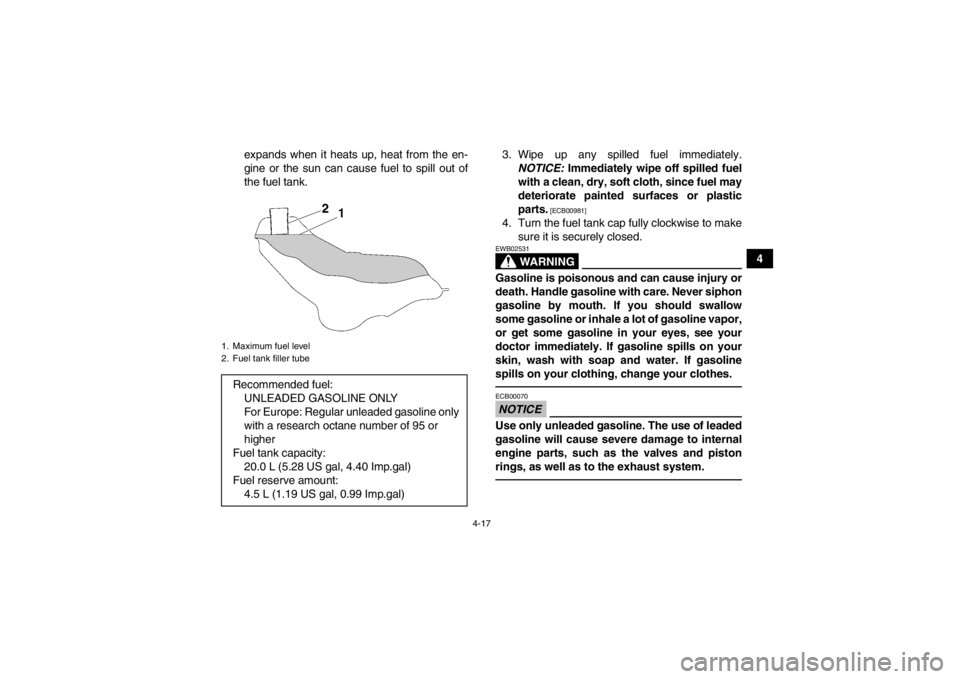
2. Do not overfill the fuel tank. When refueling, be sure to insert the pump nozzle into the fuel
tank filler hole. Stop filling when the fuel reach-
es the bottom of the filler tube. Because fuel
1. Fuel tank cap cover
1. Fuel tank capU1HS61E0.book Page 16 Wednesday, May 23, 2012 5:24 PM
Page 47 of 174
4-17
4
expands when it heats up, heat from the en-
gine or the sun can cause fuel to spill out of
the fuel tank.
3. Wipe up any spilled fuel immediately.
NOTICE: Immediately wipe off spilled fuel
with a clean, dry, soft cloth, since fuel may
deteriorate painted surfaces or plastic
parts.
[ECB00981]
4. Turn the fuel tank cap fully clockwise to make sure it is securely closed.
WARNING
EWB02531Gasoline is poisonous and can cause injury or
death. Handle gasoline with care. Never siphon
gasoline by mouth. If you should swallow
some gasoline or inhale a lot of gasoline vapor,
or get some gasoline in your eyes, see your
doctor immediately. If gasoline spills on your
skin, wash with soap and water. If gasoline
spills on your clothing, change your clothes.NOTICEECB00070Use only unleaded gasoline. The use of leaded
gasoline will cause severe damage to internal
engine parts, such as the valves and piston
rings, as well as to the exhaust system.
1. Maximum fuel level
2. Fuel tank filler tubeRecommended fuel:UNLEADED GASOLINE ONLY
For Europe: Regular unleaded gasoline only
with a research octane number of 95 or
higher
Fuel tank capacity: 20.0 L (5.28 US gal, 4.40 Imp.gal)
Fuel reserve amount: 4.5 L (1.19 US gal, 0.99 Imp.gal)
U1HS61E0.book Page 17 Wednesday, May 23, 2012 5:24 PM